EP0388352A1 - Dispositif pour barrière optique à une seule direction - Google Patents
Dispositif pour barrière optique à une seule direction Download PDFInfo
- Publication number
- EP0388352A1 EP0388352A1 EP90810116A EP90810116A EP0388352A1 EP 0388352 A1 EP0388352 A1 EP 0388352A1 EP 90810116 A EP90810116 A EP 90810116A EP 90810116 A EP90810116 A EP 90810116A EP 0388352 A1 EP0388352 A1 EP 0388352A1
- Authority
- EP
- European Patent Office
- Prior art keywords
- transmitters
- transmitter
- light barrier
- receivers
- receiver
- Prior art date
- Legal status (The legal status is an assumption and is not a legal conclusion. Google has not performed a legal analysis and makes no representation as to the accuracy of the status listed.)
- Withdrawn
Links
Images


Classifications
-
- G—PHYSICS
- G08—SIGNALLING
- G08B—SIGNALLING SYSTEMS, e.g. PERSONAL CALLING SYSTEMS; ORDER TELEGRAPHS; ALARM SYSTEMS
- G08B13/00—Burglar, theft or intruder alarms
- G08B13/18—Actuation by interference with heat, light, or radiation of shorter wavelength; Actuation by intruding sources of heat, light, or radiation of shorter wavelength
- G08B13/181—Actuation by interference with heat, light, or radiation of shorter wavelength; Actuation by intruding sources of heat, light, or radiation of shorter wavelength using active radiation detection systems
- G08B13/183—Actuation by interference with heat, light, or radiation of shorter wavelength; Actuation by intruding sources of heat, light, or radiation of shorter wavelength using active radiation detection systems by interruption of a radiation beam or barrier
-
- G—PHYSICS
- G08—SIGNALLING
- G08B—SIGNALLING SYSTEMS, e.g. PERSONAL CALLING SYSTEMS; ORDER TELEGRAPHS; ALARM SYSTEMS
- G08B29/00—Checking or monitoring of signalling or alarm systems; Prevention or correction of operating errors, e.g. preventing unauthorised operation
- G08B29/18—Prevention or correction of operating errors
Definitions
- the invention relates to a one-way light barrier arrangement with a series of monitoring sections or data and / or signal transmission sections, a transmitter and a receiver being provided for each section.
- the one-way light barrier arrangement contains two types of transmitters and receivers, the first type being a linear polarization filter with a first polarization level and the second type has a linear polarization filter with a second polarization level, which is arranged at an angle to the first polarization level, and that the transmitter and receiver are of the same type for the respective route.
- first type being a linear polarization filter with a first polarization level
- second type has a linear polarization filter with a second polarization level, which is arranged at an angle to the first polarization level, and that the transmitter and receiver are of the same type for the respective route.
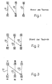
- a one-way light barrier arrangement is thus possible, in which all transmitters are arranged on one side and all receivers on the other side if the lines are alternately equipped with one or the other type of transmitters and receivers (FIG. 3). With this arrangement, stray light from the neighboring route does not interfere. Only stray light from a third distance could have a disturbing effect, provided that it is still of sufficient intensity.
- An embodiment is even more advantageous, which is characterized in that transmitters or receivers are alternately arranged in groups of two on one side or the other side, and that in successive routes the transmitters and receivers are alternately of the first or the second type ( Fig. 4).
- only the fifth route is in turn configured the same as the first, so that only the receiver of the fifth route could be influenced by stray light from the first route.
- the fifth route is far away, either no stray light falls on the receiver or the striking stray light is so low in intensity that it has no effect.
- the angle between the first and the second plane of polarization is advantageously 90 degrees. At this angle, influencing of a receiver of the second type by a transmitter of the first type is practically impossible, because then practically all striking polarized light is filtered out.
- An advantageous arrangement provides that the even-numbered segments are arranged in a first plane and the odd-numbered segments in a second plane, which extends at a distance parallel to the first plane (FIG. 6). This arrangement is particularly advantageous if the transmitter and receiver have a common fastening axis, which allows such an arrangement.
- the transmitters S1, S2, S3 are arranged on one side, the receivers E1, E2, E3 on the other side. As shown in dash-dotted lines, there is a risk that stray light from a transmitter, e.g. S1, the receiver, e.g. E2, which can affect the neighboring route.
- the transmission directions in the known arrangement from FIG. 2 are alternately different.
- the transmitter S1, the receiver E2 and the transmitter S3 are arranged on the one side, while the receiver E1, the transmitter S2 and the receiver E3 are located on the other side.
- stray light from one route cannot affect the receiver of the neighboring route.
- a number of distances D1, D2, D3 ... are again provided.
- the first type contains a linear polarization filter with a first polarization plane that is indicated with four vertical lines.
- the second type contains a linear polarization filter with a second polarization plane, which is indicated by four horizontal lines.
- the second polarization plane is arranged at an angle of 90 degrees to the first polarization plane.
- the transmitter and the receiver have linear polarization filters with the same polarization level; The transmitter and receiver are thus of the same type.
- the transmitters S1, S2, S3 ... are arranged on one side and the receivers E1, E2, E3 ...
- the lines D1, D2, D3 ... are equipped in sequence with transmitters and receivers of one or the other type. It can be seen that, in these circumstances, the transmitter S1, for example, cannot influence the adjacent receiver E2. Scattered light from the transmitter S1 could only influence the receiver E3, which has the same polarization as the transmitter S1.
- the embodiment of FIG. 3 does not differ from the known prior art according to FIG. 2, but has the advantage that all transmitters can be on one side or all transmitters on the other side, as is appropriate for certain applications.
- the transmitters S1, S2 are alternately of the first or second type. Furthermore, the transmitters S1, S2 are alternately in groups of two arranged on one or the other side. The groups of two are indicated by brackets.
- the same also applies to the receivers E1, E2, ... With this arrangement, for example, scattered light from the transmitter S1 cannot influence the adjacent three receivers E2, E3 and E4. Stray light from the transmitter S1 could only fall onto the receiver E5. However, this is hardly the case because the distance from the distance D1 is relatively large. Scattered light that may fall on the receiver E5 is usually of such a low intensity that it has no interference.
- the embodiment according to FIG. 5 gives the same advantage, where in successive distances D1, D2 ... the transmitters or Receivers are arranged alternately on one side and the other. Again, groups of two transmitters and receivers are provided, the transmitters and receivers being of the same type in such a group of two. The groups of two transmitters and receivers are alternately of the first and the second type, as indicated by the vertical and horizontal lines.
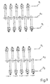
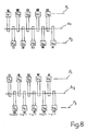
- the odd-numbered lines are arranged in a first plane P1 and the even-numbered lines in a second plane P2, which extends parallel to the first plane at a distance d.
- This arrangement is practical if the housing of the transmitter and receiver have a common fastening axis A1 or A2.
- transmitters S1, S2, ... are alternately of the first or second type. Furthermore, the transmitters S1, S2 are alternately arranged in groups of two on one side or the other. (In the schematic representation above or below in the picture). The same applies to the receivers E1, E2, ... In contrast to FIG. 4, however, the odd-numbered transmitters and receivers are arranged in the level P1 and the even-numbered ones in the level P2.
- the transmitters S1, S2, ... are alternately arranged on one side or the other. (In the schematic representation above or below in the picture). The same also applies to the receivers E1, E2, ... Furthermore, groups of two transmitters and receivers are alternately of the first or second type. In contrast to FIG. 5, however, the odd-numbered transmitters and receivers are in level P1 and the even-numbered ones in the level P2 arranged.
- the transmitter and / or receiver which are on one or the other ren side are each arranged in a common housing.
- the one-way light barrier arrangement in the form of a fork light barrier arrangement. With such a design, the transmitter and receiver can be arranged in a common housing.
- Fig. 9 shows the structure of a one-way light barrier. This consists of the transmitter S and the receiver E.
- a stabilized power supply unit 12 which is designed either for the connection of all-current or only alternating current or only direct current.
- the power supply 12 feeds a transmitter circuit 13, which allows a radiation source 14 to work either with continuous light or pulsed light. Depending on the application, the light emanating from the radiation source 14 is bundled or made slightly divergent or convergent.
- the front lens 15 is used for this purpose.
- a linear polarization filter 17 is located between the radiation source 14 and the front lens 15. The linearly polarized light reaches the receiver E via the transmission path d.
- the receiver E has a housing 21 which is advantageously of the same design as the housing 11 of the transmitter S. Behind the front lens 23 is a linear polarization filter 25, which has the same polarization plane as the polarization filter 17.
- the photoelectric converter 27, whose output signal is fed to an electronic amplifier 29, is used to receive the incident received light beam.
- An electronic evaluation stage 31 is connected to the amplifier 29 and is supplied by the stabilized power supply 33.
- the output 34 which can include a light or dark circuit or an antivalence circuit, experiences a signal change when the photoelectric converter receives a light intensity above a predetermined threshold value.
Landscapes
- Physics & Mathematics (AREA)
- General Physics & Mathematics (AREA)
- Engineering & Computer Science (AREA)
- Computer Security & Cryptography (AREA)
- Optical Communication System (AREA)
Applications Claiming Priority (2)
| Application Number | Priority Date | Filing Date | Title |
|---|---|---|---|
| CH95889 | 1989-03-15 | ||
| CH958/89 | 1989-03-15 |
Publications (1)
| Publication Number | Publication Date |
|---|---|
| EP0388352A1 true EP0388352A1 (fr) | 1990-09-19 |
Family
ID=4199132
Family Applications (1)
| Application Number | Title | Priority Date | Filing Date |
|---|---|---|---|
| EP90810116A Withdrawn EP0388352A1 (fr) | 1989-03-15 | 1990-02-19 | Dispositif pour barrière optique à une seule direction |
Country Status (1)
| Country | Link |
|---|---|
| EP (1) | EP0388352A1 (fr) |
Cited By (4)
| Publication number | Priority date | Publication date | Assignee | Title |
|---|---|---|---|---|
| EP0629370A1 (fr) * | 1993-06-11 | 1994-12-21 | Solar Wide Industrial Ltd. | Dispositif de surveillance |
| FR2801401A1 (fr) * | 1999-03-17 | 2001-05-25 | British Telecomm | Systeme de detection |
| EP2012144A1 (fr) * | 2007-07-05 | 2009-01-07 | Sick Ag | Grille lumineuse et procédé destiné au fonctionnement d'une grille lumineuse |
| CN113496581A (zh) * | 2021-07-27 | 2021-10-12 | 广州市正宏泰科贸有限公司 | 一种协同式红外栅栏入侵探测器 |
Citations (3)
| Publication number | Priority date | Publication date | Assignee | Title |
|---|---|---|---|---|
| US3440427A (en) * | 1966-04-12 | 1969-04-22 | Philips Corp | Remote control system with a unitary cell bridge circuit |
| DE2014107A1 (de) * | 1970-03-24 | 1971-10-14 | Sarl Thevon Freres | Lichtschranke |
| EP0200186A2 (fr) * | 1985-04-30 | 1986-11-05 | Cerberus Ag | Barrière photoélectrique |
-
1990
- 1990-02-19 EP EP90810116A patent/EP0388352A1/fr not_active Withdrawn
Patent Citations (3)
| Publication number | Priority date | Publication date | Assignee | Title |
|---|---|---|---|---|
| US3440427A (en) * | 1966-04-12 | 1969-04-22 | Philips Corp | Remote control system with a unitary cell bridge circuit |
| DE2014107A1 (de) * | 1970-03-24 | 1971-10-14 | Sarl Thevon Freres | Lichtschranke |
| EP0200186A2 (fr) * | 1985-04-30 | 1986-11-05 | Cerberus Ag | Barrière photoélectrique |
Cited By (5)
| Publication number | Priority date | Publication date | Assignee | Title |
|---|---|---|---|---|
| EP0629370A1 (fr) * | 1993-06-11 | 1994-12-21 | Solar Wide Industrial Ltd. | Dispositif de surveillance |
| FR2801401A1 (fr) * | 1999-03-17 | 2001-05-25 | British Telecomm | Systeme de detection |
| FR2801400A1 (fr) * | 1999-03-17 | 2001-05-25 | British Telecomm | Systeme de detection |
| EP2012144A1 (fr) * | 2007-07-05 | 2009-01-07 | Sick Ag | Grille lumineuse et procédé destiné au fonctionnement d'une grille lumineuse |
| CN113496581A (zh) * | 2021-07-27 | 2021-10-12 | 广州市正宏泰科贸有限公司 | 一种协同式红外栅栏入侵探测器 |
Similar Documents
| Publication | Publication Date | Title |
|---|---|---|
| DE60037178T2 (de) | Leuchte, optisches element und verfahren zum beleuchten eines objektes | |
| DE69413678T2 (de) | Linsensystem | |
| DE10245495A1 (de) | Einrichtung zum Richten elektromagnetischer Strahlung | |
| DE2007840A1 (de) | Lichtschrankengitter mit Lumineszenz dioden | |
| EP1003012B1 (fr) | Système optique pour la mesure de position | |
| DE2501373B2 (de) | Anordnung zur Winkel- oder Längenmessung | |
| DE3703423C2 (fr) | ||
| EP1296161A2 (fr) | Barrière optique à séparateur de faisceaux | |
| DE2639802B2 (de) | Verfahren und Anordnung zum berührungsfreien optischen Messen eines Gegenstandsquerschnitts | |
| EP0395844A2 (fr) | Dispositif de mesure de position à points de repère | |
| EP2037296A2 (fr) | Barrière lumineuse | |
| DE102010044875A1 (de) | Beleuchtungsvorrichtung zur Erzeugung einer linienförmigen Intensitätsverteilung in einer Arbeitsebene | |
| DE202008004711U1 (de) | Lichtgitterkaskadierung | |
| DE2539438C3 (de) | Strahlenschranke | |
| EP0264027A2 (fr) | Dispositif de rideau à lumière | |
| EP0104576A2 (fr) | Réseau de couplage optique pour le couplage de plusieurs abonnés émetteurs à plusieurs abonnés récepteurs au moyen de coupleurs en étoile | |
| DE1813743C3 (de) | Anordnung zur Abtastung eines Feldes in zwei Richtungen | |
| CH681749A5 (fr) | ||
| EP0909121A2 (fr) | Module électronique d'entrée / sortie | |
| EP0039424A2 (fr) | Dispositif de mise au point pour rideau de lumière | |
| DE10106155A1 (de) | Strahlformungsvorrichtung für die Formung des Querschnitts eines Lichtstrahls sowie Anordnung zur Einkopplung eines von einer langgestreckten Laserlichtquelle ausgehenden Lichtstrahls mit einem länglichen Querschnitt in eine Lichtleitfaser | |
| DE102010045620A1 (de) | Vorrichtung zur Erzeugung einer linienförmigen Intensitätsverteilung in einer Arbeitsebene | |
| WO2003028262A1 (fr) | Procede et dispositif de distribution et de concentration d'ondes electromagnetiques | |
| DE202005017006U1 (de) | Lichtschranke mit Lichtschrankeneinheiten | |
| DE10242921A1 (de) | Ethernet-Stecker, Ethernet-Endgerät sowie Ethernet-Kommunikationssystem |
Legal Events
| Date | Code | Title | Description |
|---|---|---|---|
| PUAI | Public reference made under article 153(3) epc to a published international application that has entered the european phase |
Free format text: ORIGINAL CODE: 0009012 |
|
| AK | Designated contracting states |
Kind code of ref document: A1 Designated state(s): AT BE CH DE DK ES FR GB GR IT LI LU NL SE |
|
| 17P | Request for examination filed |
Effective date: 19900917 |
|
| 17Q | First examination report despatched |
Effective date: 19930210 |
|
| STAA | Information on the status of an ep patent application or granted ep patent |
Free format text: STATUS: THE APPLICATION IS DEEMED TO BE WITHDRAWN |
|
| 18D | Application deemed to be withdrawn |
Effective date: 19940406 |