EP0388384B1 - Mechanische Dichtung - Google Patents
Mechanische Dichtung Download PDFInfo
- Publication number
- EP0388384B1 EP0388384B1 EP90850083A EP90850083A EP0388384B1 EP 0388384 B1 EP0388384 B1 EP 0388384B1 EP 90850083 A EP90850083 A EP 90850083A EP 90850083 A EP90850083 A EP 90850083A EP 0388384 B1 EP0388384 B1 EP 0388384B1
- Authority
- EP
- European Patent Office
- Prior art keywords
- seal
- shaft
- spring
- rings
- cup
- Prior art date
- Legal status (The legal status is an assumption and is not a legal conclusion. Google has not performed a legal analysis and makes no representation as to the accuracy of the status listed.)
- Expired - Lifetime
Links
- 238000007789 sealing Methods 0.000 claims abstract description 13
- 238000005086 pumping Methods 0.000 claims description 3
- 230000032258 transport Effects 0.000 claims 1
- 239000002826 coolant Substances 0.000 abstract 1
- 239000000314 lubricant Substances 0.000 abstract 1
- 238000001816 cooling Methods 0.000 description 2
- 230000003467 diminishing effect Effects 0.000 description 1
- 239000012530 fluid Substances 0.000 description 1
- 230000008642 heat stress Effects 0.000 description 1
Images
Classifications
-
- F—MECHANICAL ENGINEERING; LIGHTING; HEATING; WEAPONS; BLASTING
- F16—ENGINEERING ELEMENTS AND UNITS; GENERAL MEASURES FOR PRODUCING AND MAINTAINING EFFECTIVE FUNCTIONING OF MACHINES OR INSTALLATIONS; THERMAL INSULATION IN GENERAL
- F16J—PISTONS; CYLINDERS; SEALINGS
- F16J15/00—Sealings
- F16J15/16—Sealings between relatively-moving surfaces
- F16J15/34—Sealings between relatively-moving surfaces with slip-ring pressed against a more or less radial face on one member
- F16J15/3404—Sealings between relatively-moving surfaces with slip-ring pressed against a more or less radial face on one member and characterised by parts or details relating to lubrication, cooling or venting of the seal
-
- F—MECHANICAL ENGINEERING; LIGHTING; HEATING; WEAPONS; BLASTING
- F03—MACHINES OR ENGINES FOR LIQUIDS; WIND, SPRING, OR WEIGHT MOTORS; PRODUCING MECHANICAL POWER OR A REACTIVE PROPULSIVE THRUST, NOT OTHERWISE PROVIDED FOR
- F03B—MACHINES OR ENGINES FOR LIQUIDS
- F03B11/00—Parts or details not provided for in, or of interest apart from, the preceding groups, e.g. wear-protection couplings, between turbine and generator
- F03B11/006—Sealing arrangements
-
- F—MECHANICAL ENGINEERING; LIGHTING; HEATING; WEAPONS; BLASTING
- F04—POSITIVE - DISPLACEMENT MACHINES FOR LIQUIDS; PUMPS FOR LIQUIDS OR ELASTIC FLUIDS
- F04D—NON-POSITIVE-DISPLACEMENT PUMPS
- F04D29/00—Details, component parts, or accessories
- F04D29/08—Sealings
- F04D29/10—Shaft sealings
- F04D29/12—Shaft sealings using sealing-rings
- F04D29/126—Shaft sealings using sealing-rings especially adapted for liquid pumps
- F04D29/128—Shaft sealings using sealing-rings especially adapted for liquid pumps with special means for adducting cooling or sealing fluid
-
- B—PERFORMING OPERATIONS; TRANSPORTING
- B01—PHYSICAL OR CHEMICAL PROCESSES OR APPARATUS IN GENERAL
- B01F—MIXING, e.g. DISSOLVING, EMULSIFYING OR DISPERSING
- B01F35/00—Accessories for mixers; Auxiliary operations or auxiliary devices; Parts or details of general application
- B01F35/30—Driving arrangements; Transmissions; Couplings; Brakes
- B01F2035/35—Use of other general mechanical engineering elements in mixing devices
- B01F2035/351—Sealings
-
- Y—GENERAL TAGGING OF NEW TECHNOLOGICAL DEVELOPMENTS; GENERAL TAGGING OF CROSS-SECTIONAL TECHNOLOGIES SPANNING OVER SEVERAL SECTIONS OF THE IPC; TECHNICAL SUBJECTS COVERED BY FORMER USPC CROSS-REFERENCE ART COLLECTIONS [XRACs] AND DIGESTS
- Y02—TECHNOLOGIES OR APPLICATIONS FOR MITIGATION OR ADAPTATION AGAINST CLIMATE CHANGE
- Y02E—REDUCTION OF GREENHOUSE GAS [GHG] EMISSIONS, RELATED TO ENERGY GENERATION, TRANSMISSION OR DISTRIBUTION
- Y02E10/00—Energy generation through renewable energy sources
- Y02E10/20—Hydro energy
Definitions
- This invention concerns a mechanical seal in a seal arrangement for a submersible rotary machine such as a pump, a mixer or a turbine.
- a machine of this type normally comprises an electrically driven motor and a hydraulic unit having a rotary impeller connected to the motor via a driving shaft.
- seal units In order to prevent the medium in the hydraulic unit from moving along the driving shaft and enter the driving motor and damage it, there are one or several seal units arranged between the hydraulic unit and the motor.
- An often used seal is the so-called mechanical seal which consists of one seal ring attached to the rotating shaft and one stationary seal ring attached to the surrounding housing. The two seal rings are pressed towards each other by spring force and prevent effectively fluid from passing between the two rings.
- the oil in the oilhousing shall also lubricate the sealing surfaces and abduct the heat that is obtained by the friction. If the machine should operate dry and there is no pumped or mixed medium to abduct the heat, the strain can be considerable.
- the purpose of this invention is to increase the cooling of the sealing surface by help of the device stated in the claims.
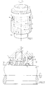
- Fig 1 shows a principle sketch of a spring housing with a spring
- Fig 2 shows a section of a spring housing and a mechanical seal on a shaft.
- FIG. 1 stands for a rotary shaft, 2 and 3 a stationary and a rotary seal ring respectively, 4 the sealing surface between the two rings, 5 a spring, 6 a cup formed like a spring housing having openings 7, 8 and 9 O-rings, 10 a socket on the shaft 1, 11 a non-rotory machine part, 12 and 13 spaces for pumped medium and oil respectively and 14 a slot between the shaft 1 and the spring housing 6.
- the mechanical seal with its rings are thus meant to prevent medium from going along the shaft 1 from the hydraulic part in the direction of the driving unit - from the space 12 towards the space 13.
- the sealing is obtained by providing a spring force on the seal ring 3 rotating with the shaft 1 which presses said ring towards the other seal ring 2 which is fixed in non-rotary parts of the machine.
- the force is obtained by a spring 5 compressed by a socket 10 and arranged in a spring housing 6 provided with a collar which surrounds an extension on the seal ring 3.
- a sealing between seal ring 3 and socket 10 and between the latter and the shaft 1 is obtained by O-rings.
- the space 13 and the spring housing 6 are filled with oil which lubricates and cools the seal.
- the friction heat which is developped in the sealing surface 4, can be considerable and may be difficult to abduct at dry running.
- the spring 5 and the spring housing 6 are so designed that a forced circulation of oil is obtained within the area of the seal surface 4.
- the spring housing 6 is provided with a slot 14 near the shaft at its one end and with openings 7 at its mantle surface in its other end within the area of the sealing surface 4 previously mentioned.
- This design means that the spring housing 6 will operate as a centrifugal pump which takes in oil from the space 13 through the slot 14 and pumps it out through the openings 7.
- the transport back to the space 13 takes place outside the housing 6. In this way a forced flow of oil is obtained which gives an effective cooling of the seal surface 4.
- the spring 5 is so wound around the shaft 1 that the pumping is strengthened. This is obtained by arranging the spring coils in such a way that they feed the oil in the same direction towards the seal.
- the spring housing 6 is utilized for obtaining the forced flow of oil in the direction towards the seal. It is, however, also possible, within the limits of the invention, to design the housing 6 only for pumping purposes, while the spring is arranged somewhere else.
Landscapes
- Engineering & Computer Science (AREA)
- General Engineering & Computer Science (AREA)
- Mechanical Engineering (AREA)
- Chemical & Material Sciences (AREA)
- Combustion & Propulsion (AREA)
- Mechanical Sealing (AREA)
Claims (3)
- Mechanische Dichtung mit einem umlaufenden (3) und einem stationären (2) Dichtungsring zum Abdichten einer Antriebseinheit von einer Hydraulikeinheit, die durch eine rotierende Antriebswelle (1) verbunden sind, wobei die beiden Dichtungsringe durch Federkraft gegeneinander gedrückt werden,
dadurch gekennzeichnet, daß ein Becher (6) radial innerhalb des Umfangs der Dichtungsringe (2) bzw. (3) um die Welle (1) herum angeordnet ist, wobei der Becher (6) auf seiner Mantelfläche in der Nähe der Dichtungsfläche (4) zwischen den beiden Ringen (2) und (3) mit Öffnungen (7) versehen ist und in seinem anderen Ende nahe der Welle (1) mit einem Schlitz (14) versehen ist, wobei letzteres Ende in einem die Welle (1) umgebenden Ölraum (13) angeordnet ist und wobei der Becher (6) während einer Rotationsbewegung als Pumpe wirkt, die Öl von dem Raum (13) in Richtung auf die Dichtungsfläche (4) transportiert. - Mechanische Dichtung nach Anspruch 1,
dadurch gekennzeichnet, daß der Becher (6) als Gehäuse für eine Schraubenfeder (5) ausgelegt ist, die die auf die Dichtungsringe (2) und (3) wirkende Federkraft liefert. - Mechanische Dichtung nach Anspruch 2,
dadurch gekennzeichnet, daß die Feder (5) in einer derartigen Richtung um die Welle (1) gewickelt ist, daß sich eine schraubenlinienförmige Linie ergibt, die zu einer Förderrichtung in derselben Richtung wie die Pumprichtung führt.
Priority Applications (1)
| Application Number | Priority Date | Filing Date | Title |
|---|---|---|---|
| AT9090850083T ATE105384T1 (de) | 1989-03-16 | 1990-02-28 | Mechanische dichtung. |
Applications Claiming Priority (2)
| Application Number | Priority Date | Filing Date | Title |
|---|---|---|---|
| SE8900936 | 1989-03-16 | ||
| SE8900936A SE461677B (sv) | 1989-03-16 | 1989-03-16 | Plantaetning |
Publications (2)
| Publication Number | Publication Date |
|---|---|
| EP0388384A1 EP0388384A1 (de) | 1990-09-19 |
| EP0388384B1 true EP0388384B1 (de) | 1994-05-04 |
Family
ID=20375366
Family Applications (1)
| Application Number | Title | Priority Date | Filing Date |
|---|---|---|---|
| EP90850083A Expired - Lifetime EP0388384B1 (de) | 1989-03-16 | 1990-02-28 | Mechanische Dichtung |
Country Status (7)
| Country | Link |
|---|---|
| EP (1) | EP0388384B1 (de) |
| JP (1) | JPH0756346B2 (de) |
| AT (1) | ATE105384T1 (de) |
| AU (1) | AU621194B2 (de) |
| CA (1) | CA2012114A1 (de) |
| DE (1) | DE69008598T2 (de) |
| SE (1) | SE461677B (de) |
Cited By (1)
| Publication number | Priority date | Publication date | Assignee | Title |
|---|---|---|---|---|
| EP4048901B1 (de) * | 2019-10-21 | 2023-05-24 | Sulzer Management AG | Pumpenanordnung zum pumpen einer sperrflüssigkeit und mechanische wellendichtung |
Families Citing this family (8)
| Publication number | Priority date | Publication date | Assignee | Title |
|---|---|---|---|---|
| GB8909504D0 (en) * | 1989-04-26 | 1989-06-14 | Weir Pumps Ltd | Pump with seal cooling means |
| GB2286020B (en) * | 1994-02-01 | 1996-08-28 | Keith Charles Garrett | Mechanical shaft seals |
| US5718436A (en) * | 1996-07-30 | 1998-02-17 | Dunford; Joseph R. | Flow controller for mechanical seal protection |
| TW350007B (en) * | 1997-07-14 | 1999-01-11 | Tsurumi Mfg | Structure for retaining lubrication oil at sliding surface of shaft seal device disposed within oil chamber of submersible pump |
| DE10013153A1 (de) * | 2000-03-17 | 2001-10-11 | Ksb Ag | Dichtungsgehäuse für Gleitringdichtungen |
| CA2366885A1 (en) * | 2001-12-31 | 2003-06-30 | Rammy A. Shellef | External mechanical seals for rotating equipment |
| CN101858435B (zh) * | 2009-04-10 | 2011-11-09 | 江苏华阳重工科技股份有限公司 | 水压自平衡机械密封装置 |
| DE102019206205B3 (de) * | 2019-04-30 | 2020-07-09 | Eagleburgmann Germany Gmbh & Co. Kg | Gleitringdichtungsanordnung, insbesondere für heiße Medien, sowie Pumpenanordnung |
Family Cites Families (5)
| Publication number | Priority date | Publication date | Assignee | Title |
|---|---|---|---|---|
| SE165994C1 (de) * | ||||
| US1781685A (en) * | 1929-02-08 | 1930-11-18 | Timken Roller Bearing Co | Shaft inclosure |
| US2956824A (en) * | 1957-12-27 | 1960-10-18 | Koppers Co Inc | Vented shaft seal |
| US3746349A (en) * | 1970-08-26 | 1973-07-17 | F Robson | Mechanical seals and or thrust bearings |
| JPS5519948A (en) * | 1978-07-28 | 1980-02-13 | Shin Meiwa Ind Co Ltd | Device for sealing shaft of vertical pump |
-
1989
- 1989-03-16 SE SE8900936A patent/SE461677B/sv not_active IP Right Cessation
-
1990
- 1990-02-08 AU AU49366/90A patent/AU621194B2/en not_active Ceased
- 1990-02-28 DE DE69008598T patent/DE69008598T2/de not_active Expired - Fee Related
- 1990-02-28 EP EP90850083A patent/EP0388384B1/de not_active Expired - Lifetime
- 1990-02-28 AT AT9090850083T patent/ATE105384T1/de not_active IP Right Cessation
- 1990-03-14 CA CA002012114A patent/CA2012114A1/en not_active Abandoned
- 1990-03-15 JP JP2065533A patent/JPH0756346B2/ja not_active Expired - Fee Related
Cited By (1)
| Publication number | Priority date | Publication date | Assignee | Title |
|---|---|---|---|---|
| EP4048901B1 (de) * | 2019-10-21 | 2023-05-24 | Sulzer Management AG | Pumpenanordnung zum pumpen einer sperrflüssigkeit und mechanische wellendichtung |
Also Published As
| Publication number | Publication date |
|---|---|
| JPH0756346B2 (ja) | 1995-06-14 |
| CA2012114A1 (en) | 1990-09-16 |
| JPH02278081A (ja) | 1990-11-14 |
| SE8900936D0 (sv) | 1989-03-16 |
| EP0388384A1 (de) | 1990-09-19 |
| DE69008598D1 (de) | 1994-06-09 |
| DE69008598T2 (de) | 1994-08-25 |
| SE461677B (sv) | 1990-03-12 |
| AU621194B2 (en) | 1992-03-05 |
| AU4936690A (en) | 1990-09-20 |
| ATE105384T1 (de) | 1994-05-15 |
Similar Documents
| Publication | Publication Date | Title |
|---|---|---|
| EP0252037A1 (de) | Dichtungsvorrichtung | |
| US5553867A (en) | Triple cartridge seal having one inboard and two concentric seals for chemical processing pump | |
| EP0037210A1 (de) | Zur Hochdruckseite pumpende Dichtungskombination | |
| US2830541A (en) | Fluid bearing for a tubular rotating shaft | |
| KR20200021943A (ko) | 유동 기계용 베어링 하우징 및 베어링 하우징을 갖는 유동 기계 | |
| US6446975B1 (en) | Seal arrangement | |
| EP0388384A1 (de) | Mechanische Dichtung | |
| AU664684B2 (en) | Helical gear fluid machine | |
| CA2248849C (en) | Dry-pit submersible pump and liquid transfer method | |
| EP0843115B1 (de) | Dichtungsanordnung für tauchfähgige Maschinen mit einem elektrischen Motor/Generator | |
| EP0945656A2 (de) | Dichtungsring | |
| US4279571A (en) | Pitot pump with fluid lubricated bearings | |
| US5984627A (en) | Seal/bearing apparatus | |
| EP1014538B1 (de) | Elastischer Klemmring | |
| US2034790A (en) | Pipe line pump unit | |
| EP0477153A1 (de) | Dichtung | |
| CA2040869C (en) | Pump bearing system | |
| US6632075B2 (en) | Sealing and cooling device | |
| CA2190442C (en) | Mounting device | |
| GB1600673A (en) | Oilroom | |
| EP0490846A1 (de) | Untertauchbare Maschine | |
| GB2099229A (en) | Rotary dynamoelectric machine | |
| RU2076956C1 (ru) | Пластинчатая гидромашина | |
| EP0192621A1 (de) | Dichtungsanlage | |
| CN120153183A (zh) | 具有迷宫式密封件的电力驱动模块 |
Legal Events
| Date | Code | Title | Description |
|---|---|---|---|
| PUAI | Public reference made under article 153(3) epc to a published international application that has entered the european phase |
Free format text: ORIGINAL CODE: 0009012 |
|
| AK | Designated contracting states |
Kind code of ref document: A1 Designated state(s): AT DE FR GB IT NL |
|
| 17P | Request for examination filed |
Effective date: 19901008 |
|
| RAP1 | Party data changed (applicant data changed or rights of an application transferred) |
Owner name: ITT FLYGT AKTIEBOLAG |
|
| 17Q | First examination report despatched |
Effective date: 19930713 |
|
| GRAA | (expected) grant |
Free format text: ORIGINAL CODE: 0009210 |
|
| AK | Designated contracting states |
Kind code of ref document: B1 Designated state(s): AT DE FR GB IT NL |
|
| REF | Corresponds to: |
Ref document number: 105384 Country of ref document: AT Date of ref document: 19940515 Kind code of ref document: T |
|
| REF | Corresponds to: |
Ref document number: 69008598 Country of ref document: DE Date of ref document: 19940609 |
|
| ET | Fr: translation filed | ||
| ITF | It: translation for a ep patent filed | ||
| PLBE | No opposition filed within time limit |
Free format text: ORIGINAL CODE: 0009261 |
|
| STAA | Information on the status of an ep patent application or granted ep patent |
Free format text: STATUS: NO OPPOSITION FILED WITHIN TIME LIMIT |
|
| 26N | No opposition filed | ||
| REG | Reference to a national code |
Ref country code: GB Ref legal event code: IF02 |
|
| PGFP | Annual fee paid to national office [announced via postgrant information from national office to epo] |
Ref country code: NL Payment date: 20040205 Year of fee payment: 15 |
|
| PGFP | Annual fee paid to national office [announced via postgrant information from national office to epo] |
Ref country code: FR Payment date: 20040210 Year of fee payment: 15 |
|
| PGFP | Annual fee paid to national office [announced via postgrant information from national office to epo] |
Ref country code: AT Payment date: 20040211 Year of fee payment: 15 |
|
| PGFP | Annual fee paid to national office [announced via postgrant information from national office to epo] |
Ref country code: GB Payment date: 20040225 Year of fee payment: 15 |
|
| PGFP | Annual fee paid to national office [announced via postgrant information from national office to epo] |
Ref country code: DE Payment date: 20040311 Year of fee payment: 15 |
|
| PG25 | Lapsed in a contracting state [announced via postgrant information from national office to epo] |
Ref country code: IT Free format text: LAPSE BECAUSE OF NON-PAYMENT OF DUE FEES;WARNING: LAPSES OF ITALIAN PATENTS WITH EFFECTIVE DATE BEFORE 2007 MAY HAVE OCCURRED AT ANY TIME BEFORE 2007. THE CORRECT EFFECTIVE DATE MAY BE DIFFERENT FROM THE ONE RECORDED. Effective date: 20050228 Ref country code: GB Free format text: LAPSE BECAUSE OF NON-PAYMENT OF DUE FEES Effective date: 20050228 Ref country code: AT Free format text: LAPSE BECAUSE OF NON-PAYMENT OF DUE FEES Effective date: 20050228 |
|
| PG25 | Lapsed in a contracting state [announced via postgrant information from national office to epo] |
Ref country code: NL Free format text: LAPSE BECAUSE OF NON-PAYMENT OF DUE FEES Effective date: 20050901 Ref country code: DE Free format text: LAPSE BECAUSE OF NON-PAYMENT OF DUE FEES Effective date: 20050901 |
|
| GBPC | Gb: european patent ceased through non-payment of renewal fee |
Effective date: 20050228 |
|
| PG25 | Lapsed in a contracting state [announced via postgrant information from national office to epo] |
Ref country code: FR Free format text: LAPSE BECAUSE OF NON-PAYMENT OF DUE FEES Effective date: 20051031 |
|
| NLV4 | Nl: lapsed or anulled due to non-payment of the annual fee |
Effective date: 20050901 |
|
| REG | Reference to a national code |
Ref country code: FR Ref legal event code: ST Effective date: 20051031 |