EP0388525B1 - Dispositif pour le refroidissement et l'insonorisation d'une unité de compresseur d'air pressurisé - Google Patents
Dispositif pour le refroidissement et l'insonorisation d'une unité de compresseur d'air pressurisé Download PDFInfo
- Publication number
- EP0388525B1 EP0388525B1 EP89123104A EP89123104A EP0388525B1 EP 0388525 B1 EP0388525 B1 EP 0388525B1 EP 89123104 A EP89123104 A EP 89123104A EP 89123104 A EP89123104 A EP 89123104A EP 0388525 B1 EP0388525 B1 EP 0388525B1
- Authority
- EP
- European Patent Office
- Prior art keywords
- heat accumulator
- compressor unit
- sound
- unit
- container
- Prior art date
- Legal status (The legal status is an assumption and is not a legal conclusion. Google has not performed a legal analysis and makes no representation as to the accuracy of the status listed.)
- Expired - Lifetime
Links
Images


Classifications
-
- F—MECHANICAL ENGINEERING; LIGHTING; HEATING; WEAPONS; BLASTING
- F04—POSITIVE - DISPLACEMENT MACHINES FOR LIQUIDS; PUMPS FOR LIQUIDS OR ELASTIC FLUIDS
- F04B—POSITIVE-DISPLACEMENT MACHINES FOR LIQUIDS; PUMPS
- F04B39/00—Component parts, details, or accessories, of pumps or pumping systems specially adapted for elastic fluids, not otherwise provided for in, or of interest apart from, groups F04B25/00 - F04B37/00
- F04B39/06—Cooling; Heating; Prevention of freezing
-
- B—PERFORMING OPERATIONS; TRANSPORTING
- B60—VEHICLES IN GENERAL
- B60G—VEHICLE SUSPENSION ARRANGEMENTS
- B60G17/00—Resilient suspensions having means for adjusting the spring or vibration-damper characteristics, for regulating the distance between a supporting surface and a sprung part of vehicle or for locking suspension during use to meet varying vehicular or surface conditions, e.g. due to speed or load
- B60G17/02—Spring characteristics, e.g. mechanical springs and mechanical adjusting means
- B60G17/04—Spring characteristics, e.g. mechanical springs and mechanical adjusting means fluid spring characteristics
- B60G17/0408—Spring characteristics, e.g. mechanical springs and mechanical adjusting means fluid spring characteristics details, e.g. antifreeze for suspension fluid, pumps, retarding means per se
-
- F—MECHANICAL ENGINEERING; LIGHTING; HEATING; WEAPONS; BLASTING
- F04—POSITIVE - DISPLACEMENT MACHINES FOR LIQUIDS; PUMPS FOR LIQUIDS OR ELASTIC FLUIDS
- F04B—POSITIVE-DISPLACEMENT MACHINES FOR LIQUIDS; PUMPS
- F04B39/00—Component parts, details, or accessories, of pumps or pumping systems specially adapted for elastic fluids, not otherwise provided for in, or of interest apart from, groups F04B25/00 - F04B37/00
- F04B39/0027—Pulsation and noise damping means
- F04B39/0033—Pulsation and noise damping means with encapsulations
-
- B—PERFORMING OPERATIONS; TRANSPORTING
- B60—VEHICLES IN GENERAL
- B60G—VEHICLE SUSPENSION ARRANGEMENTS
- B60G2202/00—Indexing codes relating to the type of spring, damper or actuator
- B60G2202/10—Type of spring
- B60G2202/15—Fluid spring
- B60G2202/152—Pneumatic spring
-
- B—PERFORMING OPERATIONS; TRANSPORTING
- B60—VEHICLES IN GENERAL
- B60G—VEHICLE SUSPENSION ARRANGEMENTS
- B60G2600/00—Indexing codes relating to particular elements, systems or processes used on suspension systems or suspension control systems
- B60G2600/72—Cooling or warming means
Definitions
- the invention relates to a device according to the preamble of claim 1.
- a device for cooling and noise reduction of compressors and vacuum pumps for a stationary system in which the units are arranged in a closed container filled with water, which has an external cooler. Sound insulation is achieved by completely encasing the container, which is arranged at a distance from the units, with a sound-reducing layer.
- Such a device does not sufficiently dampen the noise and cannot be used in a motor vehicle due to the possible movement of the liquid in the container and the external cooling for reasons of space and because of the high cost.
- the object of the invention is to provide a device for cooling and noise insulation for a compressor unit in a motor vehicle, which avoids overloading the units by warming up and at the same time brings about improved noise insulation.
- a heat accumulator which covers the unit consisting of a pressure compressor, a motor and an air dryer over a large area, in particular in the area of the functional units, achieves heat transfer from the unit to a body wall of the vehicle, on which the unit is mounted in close contact. Due to the high heat storage capacity of the liquid consisting of water and antifreeze in the storage unit, the heat generated in the compressor unit flows away due to the temperature gradient between the unit and the heat storage unit. The warming up of the entire system is delayed and significantly more switching cycles are possible.
- the arrangement of the structural unit in sound-reducing half-shells, which enclose this unit, is inherently relatively unfavorable from a thermal point of view, which is compensated for by the heat accumulator, which is in extensive contact with the structural wall and is embedded in a half-shell and is additionally sound-reducing with this half-shell works.
- the entire unit is enclosed all around, which corresponds to an encapsulation that has a sound-reducing effect and is used for heat dissipation.
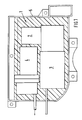
- the device is installed in a motor vehicle and essentially comprises a compressor unit 1, consisting of a compressed air compressor 2 for supplying energy to a pneumatic level control system, which is not shown in detail.
- a compressor unit 1 consisting of a compressed air compressor 2 for supplying energy to a pneumatic level control system, which is not shown in detail.
- An electric motor 3 and an air dryer 4 are connected to the compressor 2.
- This unit 1 is arranged in a bowl-shaped container 5 and is elastically supported towards the bottom 7 of the container 5 via a sound-reducing lower element 6.
- the element 6 is designed as a half-shell and surrounds the unit on all sides up to a plane X-X.
- This plane X-X runs approximately in a central transverse plane of the aggregates 3 and 4.
- the compressor unit 1 is covered with its side exposed in the container 5 by a heat accumulator 9, which is held embedded in a cutout 10 of the upper element 8.
- the half-shells of the sound-reducing elements 6 and 8 and the heat accumulator are largely adapted to the contours of the housing of the pump 2, the motor 3 and the air dryer 4, so that in particular the heat accumulator 9 has direct surface contact with these units and an optimal heat transfer is ensured .
- the bowl-shaped container 5 is connected to a body wall 10 of the vehicle against which a wall 11 of the heat accumulator 9 is in contact, whereby additional heat is dissipated.
- This wall 11 is provided opposite a further wall 12 which is in contact with the housings of the units 2, 3 and 4.
- the half-shell 8 is also adapted to the shape of the structural wall 10.
- the heat accumulator 9 preferably consists of a thin-walled plastic container, the walls of which are flexible.
- the wall 12 facing the units is made thicker than the opposite wall 11 in order to be caused by friction of the units Counteract wear.
- the heat accumulator 9 is filled with a liquid consisting of a mixture of water and antifreeze.
- the half-shells 6 and 8 enclose the unit 1 all around on the front and top and bottom in the container 5, the heat accumulator 9 also having a sound-reducing effect in addition to its function as a heat-dissipating element, and for this purpose it is inserted in an opening 13 in the upper half-shell 8, as shown in FIG. 2 shows in more detail. Furthermore, Fig. 2 also shows that the heat accumulator 9 mainly covers the most heat-producing electric motor 3 and the air dryer 4, which are essential sources of heat, so that heat transfer to the compressed air compressor 2 is prevented. A further extension e.g. Over the entire unit 1 is also possible, especially since a sound reduction is also achieved by the heat accumulator.
Landscapes
- Engineering & Computer Science (AREA)
- Mechanical Engineering (AREA)
- General Engineering & Computer Science (AREA)
- Compressor (AREA)
- Compressors, Vaccum Pumps And Other Relevant Systems (AREA)
- Air-Conditioning For Vehicles (AREA)
Claims (6)
- Dispositif de refroidissement et d'insonorisation d'une unité de compresseur d'air comprimé (1) pour alimenter en énergie une installation pneumatique de réglage de niveau d'un véhicule automobile, qui comprend plusieurs groupes assemblés en une unité de construction, tels qu'un moteur électrique (3), un séchoir d'air (4) ainsi qu'un compresseur (2), qui sont placés dans un conteneur (5) maintenu dans la carrosserie du véhicule et entourés par des couches (6, 8) amortissant le bruit, caractérisé en ce que l'unité de compresseur (1) est logée dans des éléments en couches (6 et 8) réduisant le bruit d'un conteneur (5) en forme de coquille et est recouverte par un accumulateur de chaleur (9) qui est en contact de surface avec les groupes (2, 3 et 4) et qui est placé dans un élément en couches (8) et qui avec l'autre élément en couches (6) entoure tout autour l'unité (1) en la blindant.
- Dispositif selon la revendication 1, caractérisé en ce que l'accumulateur de chaleur (9) est constitué d'un réservoir en matière plastique à parois minces dont les parois (11, 12) sont flexibles et s'appliquent sur une grande surface sur le carter du séchoir d'air (4) et du moteur (3) ainsi que sur une paroi (10) de la carrosserie.
- Dispositif selon les revendications 1 ou 2, caractérisé en ce que les parois (11, 12) de l'accumulateur de chaleur (9) présentent une forme qui suit les contours du carter de l'unité de compresseur (1) et de la paroi (10) de la carrosserie.
- Dispositif selon les revendications 1, 2 ou 3, caractérisé en ce que les parois (11, 12) opposées l'une à l'autre de l'accumulateur de chaleur (9) présentent une grande surface et sont dirigées d'une part vers les carters de l'unité de compresseur (1) et d'autre part vers la paroi (10) de la carrosserie.
- Dispositif selon une ou plusieurs des revendications précédentes, caractérisé en ce que l'accumulateur de chaleur (9) contient un mélange liquide d'eau et de produit antigel.
- Dispositif selon une ou plusieurs des revendications précédentes, caractérisé en ce que l'une des couches (6) réduisant le bruit est constituée d'une première demi-coquille soutenant l'unité de compresseur (1) dans le conteneur (5) et l'autre couche (8) d'une seconde demi-coquille complétée par l'accumulateur de chaleur (9).
Applications Claiming Priority (2)
| Application Number | Priority Date | Filing Date | Title |
|---|---|---|---|
| DE3909563A DE3909563A1 (de) | 1989-03-23 | 1989-03-23 | Vorrichtung zur kuehlung und geraeuschdaempfung einer druckluftkompressoreinheit |
| DE3909563 | 1989-03-23 |
Publications (2)
| Publication Number | Publication Date |
|---|---|
| EP0388525A1 EP0388525A1 (fr) | 1990-09-26 |
| EP0388525B1 true EP0388525B1 (fr) | 1993-03-03 |
Family
ID=6377039
Family Applications (1)
| Application Number | Title | Priority Date | Filing Date |
|---|---|---|---|
| EP89123104A Expired - Lifetime EP0388525B1 (fr) | 1989-03-23 | 1989-12-14 | Dispositif pour le refroidissement et l'insonorisation d'une unité de compresseur d'air pressurisé |
Country Status (2)
| Country | Link |
|---|---|
| EP (1) | EP0388525B1 (fr) |
| DE (2) | DE3909563A1 (fr) |
Cited By (4)
| Publication number | Priority date | Publication date | Assignee | Title |
|---|---|---|---|---|
| US6336454B1 (en) | 1997-05-16 | 2002-01-08 | Resmed Limited | Nasal ventilation as a treatment for stroke |
| US6397841B1 (en) | 1997-06-18 | 2002-06-04 | Resmed Limited | Apparatus for supplying breathable gas |
| US6526974B1 (en) | 1995-09-18 | 2003-03-04 | John William Ernest Brydon | Pressure control in CPAP treatment or assisted respiration |
| US6532957B2 (en) | 1996-09-23 | 2003-03-18 | Resmed Limited | Assisted ventilation to match patient respiratory need |
Families Citing this family (11)
| Publication number | Priority date | Publication date | Assignee | Title |
|---|---|---|---|---|
| EP0549299B1 (fr) | 1991-12-20 | 2002-03-13 | Resmed Limited | Respirateur pour la ventilation en pression positive continue (CPAP) |
| DE19522895C2 (de) * | 1995-06-23 | 1998-10-15 | Daimler Benz Ag | Aus zwei Halbschalen bestehende, ein Geräusche abgebendes Bauteil in einem Kraftwagen umgebende Kunststoffverkleidung |
| AUPP015097A0 (en) * | 1997-11-03 | 1997-11-27 | Resmed Limited | A mounting body |
| DE19820818C2 (de) * | 1998-05-09 | 2002-12-05 | Viessmann Werke Kg | Wärmepumpe |
| US7398855B2 (en) * | 2004-05-14 | 2008-07-15 | Emerson Climate Technologies, Inc. | Compressor sound attenuation enclosure |
| DE102008027207A1 (de) * | 2008-06-06 | 2009-12-10 | Bayerische Motoren Werke Aktiengesellschaft | Kraftfahrzeug mit einem Motorraum |
| DE102010045781A1 (de) * | 2010-08-27 | 2012-03-01 | Spheros Gmbh | Vorrichtung zur schwingungsdämpfenden Lagerung eines Aggregats |
| DE102011003133A1 (de) * | 2011-01-25 | 2012-07-26 | Bayerische Motoren Werke Aktiengesellschaft | Maschinenhalterung in einem Fahrzeug |
| US9153225B2 (en) | 2011-12-16 | 2015-10-06 | Emerson Climate Technologies, Inc. | Sound enclosure for enclosing a compressor assembly |
| DE102019131835A1 (de) * | 2019-11-25 | 2021-05-27 | Bayerische Motoren Werke Aktiengesellschaft | Verdichtereinrichtung für ein Fahrzeug, insbesondere für ein Kraftfahrzeug, sowie Fahrzeug |
| JP7347305B2 (ja) | 2020-03-31 | 2023-09-20 | 株式会社豊田自動織機 | 電動圧縮機 |
Family Cites Families (7)
| Publication number | Priority date | Publication date | Assignee | Title |
|---|---|---|---|---|
| DE688946C (de) * | 1938-03-24 | 1940-03-06 | Siemens Schuckertwerke Akt Ges | Foerderpumpe, insbesondere Kompressor fuer Kaeltemaschinen |
| DE1051295B (de) * | 1957-02-16 | 1959-02-26 | Wilhelm Bock | Verfluessiger-Aggregat fuer Kaeltemaschinen |
| DE1809941U (de) * | 1960-02-10 | 1960-04-21 | Kloeckner Humboldt Deutz Ag | Achsangetriebener kompressor. |
| JPS4885207U (fr) * | 1972-01-18 | 1973-10-16 | ||
| GB1592218A (en) * | 1978-01-24 | 1981-07-01 | Olofsson B O E | Device for cooling and silencing of noise of a compressor or vacuum pump |
| DE2804563A1 (de) * | 1978-02-03 | 1979-08-09 | Guenter Dipl Chem Dr Koenig | Mittel gegen knospenfrass an nutz- und bluetenstraeuchern |
| DE3323561A1 (de) * | 1983-06-30 | 1984-03-15 | Daimler-Benz Ag, 7000 Stuttgart | Schaumstoff-ummantelung zur geraeuschdaemmung fuer eine luftpumpe |
-
1989
- 1989-03-23 DE DE3909563A patent/DE3909563A1/de active Granted
- 1989-12-14 EP EP89123104A patent/EP0388525B1/fr not_active Expired - Lifetime
- 1989-12-14 DE DE8989123104T patent/DE58903680D1/de not_active Expired - Fee Related
Cited By (5)
| Publication number | Priority date | Publication date | Assignee | Title |
|---|---|---|---|---|
| US6526974B1 (en) | 1995-09-18 | 2003-03-04 | John William Ernest Brydon | Pressure control in CPAP treatment or assisted respiration |
| US6532957B2 (en) | 1996-09-23 | 2003-03-18 | Resmed Limited | Assisted ventilation to match patient respiratory need |
| US6688307B2 (en) | 1996-09-23 | 2004-02-10 | Resmed Limited | Methods and apparatus for determining instantaneous elastic recoil and assistance pressure during ventilatory support |
| US6336454B1 (en) | 1997-05-16 | 2002-01-08 | Resmed Limited | Nasal ventilation as a treatment for stroke |
| US6397841B1 (en) | 1997-06-18 | 2002-06-04 | Resmed Limited | Apparatus for supplying breathable gas |
Also Published As
| Publication number | Publication date |
|---|---|
| DE3909563A1 (de) | 1990-09-27 |
| DE58903680D1 (de) | 1993-04-08 |
| EP0388525A1 (fr) | 1990-09-26 |
| DE3909563C2 (fr) | 1992-09-17 |
Similar Documents
| Publication | Publication Date | Title |
|---|---|---|
| EP0388525B1 (fr) | Dispositif pour le refroidissement et l'insonorisation d'une unité de compresseur d'air pressurisé | |
| DE69702033T2 (de) | Elektronisches Steuergerät mit Kühlkörper | |
| DE3130874C2 (de) | Elektrisch gesteuerte Niveauregelanlage für Fahrzeuge mit Luftfederung | |
| DE102015219618C5 (de) | Integrierte Luftversorgungseinheit mit Lufttrockner und Luftfedersystem, sowie Steuerung einer Luftversorgungseinheit | |
| DE4133879A1 (de) | Elektrohydraulisches aggregat zur druckregelung in bremsanlagen von fahrzeugen | |
| EP0456169A1 (fr) | Moteur électrique alimenté par convertisseur de fréquence | |
| DE29909117U1 (de) | Hermetisches Kompressoraggregat mit verbesserten Steuer- und Kontrolleinrichtungen | |
| DE4019217C2 (de) | Elektrische Fernsteuervorrichtung in Form eines Manipulators oder eines analogen Elements | |
| EP0882632A2 (fr) | Unité hydraulique pour le system de freinage d'un véhicule | |
| DE102007024320A1 (de) | Batteriemodul für ein elektrisches Handwerkzeug | |
| EP3124881A1 (fr) | Déshumidificateur à effet peltier à installer dans un récipient | |
| DE19612582A1 (de) | Antriebseinheit für ein Fahrzeug | |
| DE19512804C2 (de) | Hydraulikaggregat für eine blockiergeschützte Fahrzeugbremsanlage | |
| EP0294500A1 (fr) | Accumulateur de chaleur, en particulier pour systèmes de chauffage de véhicules automobiles utilisant la chaleur dégagée par le moteur | |
| WO1995001088A1 (fr) | Module convertisseur | |
| WO2020193064A1 (fr) | Ensemble boitier | |
| EP3027476A1 (fr) | Véhicule terrestre | |
| DE10316403A1 (de) | Schubmaststapler | |
| EP1104079B1 (fr) | Moteur électrique, en particulier pour une pompe centrifuge | |
| EP2993360A1 (fr) | Systeme hydraulique | |
| DE102005038409A1 (de) | Gehäuse für ein elektrisches Bauelement, Kondensator und Kondensatormodul | |
| EP3468845A1 (fr) | Dispositif d'actionnement électrohydraulique doté de modules de refroidissement | |
| DE19623632A1 (de) | Elektrischer Anschlußkasten | |
| DE10032306B4 (de) | Mit Motor vereinigte Steuerung und in dieser verwendete Schaltungsplatinengehäuse | |
| DE19921182A1 (de) | Behälter für elektrische Komponenten eines Fahrzeugs |
Legal Events
| Date | Code | Title | Description |
|---|---|---|---|
| PUAI | Public reference made under article 153(3) epc to a published international application that has entered the european phase |
Free format text: ORIGINAL CODE: 0009012 |
|
| AK | Designated contracting states |
Kind code of ref document: A1 Designated state(s): DE FR GB IT |
|
| 17P | Request for examination filed |
Effective date: 19901221 |
|
| 17Q | First examination report despatched |
Effective date: 19920529 |
|
| ITF | It: translation for a ep patent filed | ||
| GRAA | (expected) grant |
Free format text: ORIGINAL CODE: 0009210 |
|
| AK | Designated contracting states |
Kind code of ref document: B1 Designated state(s): DE FR GB IT |
|
| REF | Corresponds to: |
Ref document number: 58903680 Country of ref document: DE Date of ref document: 19930408 |
|
| GBT | Gb: translation of ep patent filed (gb section 77(6)(a)/1977) |
Effective date: 19930317 |
|
| ET | Fr: translation filed | ||
| PG25 | Lapsed in a contracting state [announced via postgrant information from national office to epo] |
Ref country code: GB Effective date: 19931214 |
|
| PLBE | No opposition filed within time limit |
Free format text: ORIGINAL CODE: 0009261 |
|
| STAA | Information on the status of an ep patent application or granted ep patent |
Free format text: STATUS: NO OPPOSITION FILED WITHIN TIME LIMIT |
|
| 26N | No opposition filed | ||
| GBPC | Gb: european patent ceased through non-payment of renewal fee |
Effective date: 19931214 |
|
| PG25 | Lapsed in a contracting state [announced via postgrant information from national office to epo] |
Ref country code: FR Effective date: 19940831 |
|
| PG25 | Lapsed in a contracting state [announced via postgrant information from national office to epo] |
Ref country code: DE Effective date: 19940901 |
|
| REG | Reference to a national code |
Ref country code: FR Ref legal event code: ST |
|
| PG25 | Lapsed in a contracting state [announced via postgrant information from national office to epo] |
Ref country code: IT Free format text: LAPSE BECAUSE OF NON-PAYMENT OF DUE FEES;WARNING: LAPSES OF ITALIAN PATENTS WITH EFFECTIVE DATE BEFORE 2007 MAY HAVE OCCURRED AT ANY TIME BEFORE 2007. THE CORRECT EFFECTIVE DATE MAY BE DIFFERENT FROM THE ONE RECORDED. Effective date: 20051214 |