EP0388699B1 - Leuchte - Google Patents
Leuchte Download PDFInfo
- Publication number
- EP0388699B1 EP0388699B1 EP90104187A EP90104187A EP0388699B1 EP 0388699 B1 EP0388699 B1 EP 0388699B1 EP 90104187 A EP90104187 A EP 90104187A EP 90104187 A EP90104187 A EP 90104187A EP 0388699 B1 EP0388699 B1 EP 0388699B1
- Authority
- EP
- European Patent Office
- Prior art keywords
- ribs
- lighting fixture
- fixture according
- stand
- cutouts
- Prior art date
- Legal status (The legal status is an assumption and is not a legal conclusion. Google has not performed a legal analysis and makes no representation as to the accuracy of the status listed.)
- Expired - Lifetime
Links
Images




Classifications
-
- F—MECHANICAL ENGINEERING; LIGHTING; HEATING; WEAPONS; BLASTING
- F21—LIGHTING
- F21S—NON-PORTABLE LIGHTING DEVICES; SYSTEMS THEREOF; VEHICLE LIGHTING DEVICES SPECIALLY ADAPTED FOR VEHICLE EXTERIORS
- F21S6/00—Lighting devices intended to be free-standing
- F21S6/002—Table lamps, e.g. for ambient lighting
-
- F—MECHANICAL ENGINEERING; LIGHTING; HEATING; WEAPONS; BLASTING
- F21—LIGHTING
- F21S—NON-PORTABLE LIGHTING DEVICES; SYSTEMS THEREOF; VEHICLE LIGHTING DEVICES SPECIALLY ADAPTED FOR VEHICLE EXTERIORS
- F21S6/00—Lighting devices intended to be free-standing
- F21S6/005—Lighting devices intended to be free-standing with a lamp housing maintained at a distance from the floor or ground via a support, e.g. standing lamp for ambient lighting
-
- F—MECHANICAL ENGINEERING; LIGHTING; HEATING; WEAPONS; BLASTING
- F21—LIGHTING
- F21V—FUNCTIONAL FEATURES OR DETAILS OF LIGHTING DEVICES OR SYSTEMS THEREOF; STRUCTURAL COMBINATIONS OF LIGHTING DEVICES WITH OTHER ARTICLES, NOT OTHERWISE PROVIDED FOR
- F21V17/00—Fastening of component parts of lighting devices, e.g. shades, globes, refractors, reflectors, filters, screens, grids or protective cages
- F21V17/10—Fastening of component parts of lighting devices, e.g. shades, globes, refractors, reflectors, filters, screens, grids or protective cages characterised by specific fastening means or way of fastening
- F21V17/14—Bayonet-type fastening
-
- F—MECHANICAL ENGINEERING; LIGHTING; HEATING; WEAPONS; BLASTING
- F21—LIGHTING
- F21V—FUNCTIONAL FEATURES OR DETAILS OF LIGHTING DEVICES OR SYSTEMS THEREOF; STRUCTURAL COMBINATIONS OF LIGHTING DEVICES WITH OTHER ARTICLES, NOT OTHERWISE PROVIDED FOR
- F21V21/00—Supporting, suspending, or attaching arrangements for lighting devices; Hand grips
- F21V21/06—Bases for movable standing lamps; Fixing standards to the bases
Definitions
- the invention relates to a lamp according to the preamble of claim 1.
- Luminaires with a rotatable base and a holding part, in which a lamp and a reflector are integrated are known, for example, from US Pat. No. 4,772,991.
- the rotatability of the base is ensured, for example, by the cover part (or base part) having a circumferential groove. After the cover part has been fitted into the cylindrical pot, the groove is backed in by screwing in screws, without the rotatability being restricted thereby. With this arrangement it has been shown that tilting and stiffness can occur during the rotary movement.
- An orientation light is known from EP-A 74 466, in which a transparent lamp cover is screwed onto the housing containing a glow lamp by means of a bayonet catch.
- the bayonet catch is formed by the housing having inwardly projecting ribs which are guided in a circumferential groove which has cutouts which correspond to the ribs.
- the ribs are arranged so that they allow a maximum rotation of 220 °.
- the electrical power supply takes place via a mains cable 13 with a plug, which is led into the interior of the cover 12 and from there reaches the interior of the pot 10 through a central opening of the circular disk with extension piece 14.
- a circuit board 16 is mounted, which carries the electrical components 17 used for the power supply of the lamp 1, including in particular a transformer.
- a possible operating circuit that makes the lamp suitable for dimmer operation is described, for example, in DE-OS 36 35 109.
- the electrical leads are threaded into the hinge 7 via a channel in the interior of the base part 8.
- An elastic, broad holding strap 18 is attached to the middle piece and extends in an arc shape up to the holder 5.
- the tether 18 contains two channels in which the electrical leads are led to the socket.
- the tether and socket are the subject of parallel application EP-A-389 830.
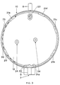
- FIG. 3 shows a view into the interior of the pot 10.
- ribs 21 projecting radially inwards are arranged, irregularly distributed over the circumference of the side walls of the pot. They are each 12 mm long (corresponding to an arc length of 14 °) and approx. 2 mm wide.
- the distribution of the ribs 21 over the circumference is chosen so that two sets of three ribs, which approximately (but not exactly!) Form an equilateral triangle (with angles that deviate from 60 ° by a maximum of 15 °), are nested within one another .
- One of the ribs, 21a is equipped with an inwardly extended nose 22, which forms a stop for an anti-twist protection.
- the spacing of the ribs from one another, starting from rib 21a is 47 ° -65 ° -51 ° -31 ° -38 ° -43 °.
- the pot 10 also contains an opening 23 in the base 15 through which the electrical lead can be inserted into the base part and the hinge 7. Furthermore, attachment points 24 for the board are also present on the bottom 15. Part of the side wall is provided with ventilation slots 25 for regulating the temperature of the electrical components.
- the closure part 11 is a circular disc 11a with raised side edges on both sides, as in Top view and shown in section in Figure 4.
- a groove 27 runs around the outside of the circular disk 11a and is delimited by side walls 28, 29 made from the meat of the circular disk.
- Corresponding recesses 26 in the pot-side wall 28 are adapted to the ribs 21 of the pot 10, so that a form-fitting placement of the closure part 11 on the pot 10 is possible.
- the ribs 21 engage in the groove 27 and catch the side wall 28 as soon as the pot and the closure part are rotated against each other.
- a screw 30 is inserted into a threaded bore in the region of a recess 26a of the closure part 11, so that it projects into the groove 27.
- an overturn protection is thereby effected and a loosening of the closure cover is prevented.
- the arrangement of the ribs or recesses is now selected so that it is ensured in every rotational position that one of the two sets of three ribs, for example 21a, 21c, 21e, forming an equilateral triangle, is guided in the groove 27 by both side walls 28, 29 becomes.
- other ribs eg 21f, can also meet this requirement.
- Optimal gliding behavior is achieved with six ribs, since then three ribs each, as it were can be decoupled in two nested triangles. The addition of further ribs worsens the sliding behavior again, since each additional rib also requires an additional recess for insertion.
- the invention is not limited to the illustrated embodiment of a lamp, but can be used with a variety of rotatable lamp housings within the meaning of the claims.
- the cover plate is equipped with standing knobs or with a center tap that can be inserted into a power rail or with holes for attachment to the wall.
Landscapes
- Engineering & Computer Science (AREA)
- General Engineering & Computer Science (AREA)
- Non-Portable Lighting Devices Or Systems Thereof (AREA)
- Storage Of Fruits Or Vegetables (AREA)
- Circuit Arrangements For Discharge Lamps (AREA)
- Lasers (AREA)
- Fastening Of Light Sources Or Lamp Holders (AREA)
- Medicines Containing Antibodies Or Antigens For Use As Internal Diagnostic Agents (AREA)
- Silicates, Zeolites, And Molecular Sieves (AREA)
- Investigating Or Analysing Biological Materials (AREA)
Description
- Die Erfindung geht aus von einer Leuchte nach dem Oberbegriff des Anspruchs 1.
- Leuchten mit einem drehbaren Standfuß und einem Halteteil, in das eine Lampe und ein Reflektor integriert sind, sind beispielsweise aus der US-A 4 772 991 bekannt.
Die Drehbarkeit des Standfußes wird bei bekannten Leuchten z.B. dadurch sichergestellt, daß das Deckelteil (bzw. Bodenteil) eine umlaufende Nut aufweist. Nach dem Einpassen des Deckelteils in den zylindrischen Topf wird die Nut durch das Eindrehen von Schrauben hinterfangen, ohne in seiner Drehbarkeit dadurch beschränkt zu werden. Bei dieser Anordnung hat sich gezeigt, daß ein Verkippen und eine Schwergängigkeit bei der Drehbewegung auftreten kann. - Aus der EP-A 74 466 ist eine Orientierungsleuchte bekannt, bei der eine transparente Lampenabdeckung durch einen Bajonettverschluß auf das eine Glimmlampe enthaltende Gehäuse aufgeschraubt wird. Der Bajonettverschluß wird gebildet, indem das Gehäuse nach innen abstehende Rippen aufweist, die in einer umlaufenden Nut geführt sind, die Aussparungen aufweist, die den Rippen entsprechen. Die Rippen sind so angeordnet, daß sie maximal eine Drehbewegung von 220° gestatten.
- Es ist Aufgabe der vorliegenden Erfindung, eine Leuchte bereitzustellen, die leichtgängig ist und bei der kein Verkippen auftreten kann.
- Diese Aufgabe wird durch die kennzeichnenden Merkmale des Anspruchs 1 gelöst. Weitere vorteilhafte Ausgestaltungen finden sich in den Unteransprüchen.
- Die Vorteile der Erfindung liegen insbesondere in der Materialeinsparung (Schrauben), der einfachen Montage und der Bedienungsfreundlichkeit.
- Nachfolgend soll ein Ausführungsbeispiel der Erfindung näher erläutert werden. Es zeigt
- Figur 1
- eine Vorderansicht einer Tischleuchte
- Figur 2
- eine Seitenansicht der Tischleuchte aus Figur 1
- Figur 3
- den zylindrischen Topf des Standfußes in Draufsicht
- Figur 4
- das Deckelteil des Standfußes in Draufsicht (a) und im Schnitt (b)
- Die elektrische Stromversorgung erfolgt über ein Netzkabel 13 mit Stecker, das in den Innenraum des Überdeckels 12 geführt ist und von dort durch eine zentrale Öffnung der Kreisscheibe mit Verlängerungsstutzen 14 in den Innenraum des Topfes 10 gelangt. Am "Boden" 15 des Topfes ist eine Platine 16 montiert, die die für die Stromversorgung der Lampe 1 verwendeten elektrischen Bauteile 17 trägt, darunter insbesondere einen Transformator. Eine mögliche Betriebsschaltung, die die Leuchte für den Dimmerbetrieb geeignet macht, ist z.B. in der DE-OS 36 35 109 beschrieben. Über einen Kanal im Innern des Basisteils 8 werden die elektrischen Zuleitungen in das Scharnier 7 eingefädelt. An dessen Mittelstück ist ein elastisches breitflächiges Halteband 18 angesetzt, das sich bogenförmig bis zur Fassung 5 erstreckt. Das Halteband 18 enthält zwei Kanäle, in denen die elektrischen Zuleitungen zur Fassung geführt werden. Halteband und Fassung sind Gegenstand der Parallelanmeldung EP-A- 389 830.
- Der Topf 10 und das Verschlußteil 11 sind mittels eines Bajonettverschlusses gegeneinander drehbar. Figur 3 zeigt einen Blick in den Innenraum des Topfes 10. Kurz unterhalb des Topfrandes 20 sind - unregelmäßig über den Umfang der Seitenwände des Topfes verteilt - sechs radial nach innen abstehende Rippen 21 angeordnet. Sie sind jeweils 12 mm lang (entsprechend einer Bogenlänge von 14°) und ca. 2 mm breit. Die Verteilung der Rippen 21 über den Umfang ist so gewählt, daß zwei Sätze von jeweils drei Rippen, die näherungsweise (jedoch nicht exakt!) ein gleichseitiges Dreieck (mit Winkeln, die von 60° maximal um 15° abweichen) bilden, ineinander verschachtelt sind. Durch diese Anordnung wird ein optimales Gleiten zwischen Topf 10 und Verschlußteil 11 sichergestellt (s. u.). Eine der Rippen, 21a, ist mit einer nach innen verlängerten Nase 22 ausgestattet, die einen Anschlag für einen Verdrehschutz bildet. Im einzelnen beträgt der Abstand der Rippen voneinander, ausgehend von Rippe 21a, 47° - 65° - 51° - 31° - 38° - 43°.
- Außer den Rippen 21 enthält der Topf 10 noch eine Öffnung 23 im Boden 15, durch die die elektrische Zuleitung in das Basisteil und das Scharnier 7 eingeführt werden kann. Ferner sind am Boden 15 noch Befestigungspunkte 24 für die Platine vorhanden. Ein Teil der Seitenwand ist mit Lüftungsschlitzen 25 zur Temperaturregulierung für die elektrischen Bauteile versehen.
- Das Verschlußteil 11 ist eine Kreisscheibe 11a mit beidseitig hochgezogenen Seitenrändern, wie in Draufsicht und im Schnitt in Figur 4 dargestellt. Oberhalb des Wulstes 19 läuft außen an der Kreisscheibe 11a eine Nut 27 um, die durch Seitenwände 28, 29 aus dem Fleisch der Kreisscheibe begrenzt ist. Den Rippen 21 des Topfes 10 sind entsprechende Aussparungen 26 in der topfseitigen Seitenwand 28 angepaßt, so daß ein formschlüssiges Aufsetzen des Verschlußteils 11 auf den Topf 10 möglich ist. Die Rippen 21 greifen dabei in die Nut 27 ein und hinterfangen die Seitenwand 28, sobald der Topf und das Verschlußteil gegeneinander verdreht werden. Als Überdrehschutz im Zusammenwirken mit der Nase 22 wird eine Schraube 30 in eine Gewindebohrung im Bereich einer Aussparung 26a des Verschlußteils 11 eingefügt, so daß sie in die Nut 27 hineinragt. Im Zusammenwirken mit der Nase 22 wird dadurch eine Überdrehsicherung bewirkt und ein Lösen des Verschlußdeckels verhindert. Die Anordnung der Rippen bzw. Aussparungen ist nun so gewählt, daß in jeder Drehstellung sichergestellt ist, daß immer einer der beiden ein gleichseitiges Dreieck bildenden Sätze von drei Rippen, z.B. 21a, 21c, 21e in der Nut 27 von beiden Seitenwänden 28, 29 geführt wird. Darüber hinaus können auch weitere Rippen, z.B. 21f, diese Bedingung erfüllen. Je mehr Rippen gleichzeitig geführt werden, desto besser sind die Gleiteigenschaften beim Drehen des Standfußes. Dieses Konzept der "Dreipunktlagerung" läßt sich minimal mit vier Rippen durchführen: wenn eine der Rippen sich über einer Aussparung befindet, bilden die jeweils drei restlichen das gleitende Dreieck.
- Ein optimales Gleitverhalten wird bei sechs Rippen erzielt, da dann jeweils drei Rippen gleichsam entkoppelt in zwei ineinander verschachtelten Dreiecken angeordnet werden können. Das Hinzufügen weiterer Rippen verschlechtert das Gleitverhalten wieder, da jede zusätzliche Rippe auch eine weitere Aussparung zum Einsetzen benötigt.
- Die Erfindung ist nicht auf das gezeigte Ausführungsbeispiel einer Leuchte beschränkt, sondern läßt sich bei einer Vielzahl von drehbaren Leuchtengehäusen im Sinne der Ansprüche verwenden. Je nachdem, ob es sich um eine Tisch-, Wand- oder Deckenleuchte handelt, ist beispielsweise der Überdeckel mit Standnoppen oder mit einem in eine Stromschiene einsetzbaren Mittenabgriff oder mit Bohrungen zur Befestigung an der Wand ausgestattet.
Claims (10)
- Leuchte mit einem Gehäuse, bestehend aus einem drehbaren ersten Gehäuseteil, das gegenüber einem zweiten Gehäuseteil mit Hilfe eines Bajonettverschlusses gedreht werden kann, der dadurch gebildet wird, daß der drehbare Gehäuseteil radial nach innen abstehende, auf einem gemeinsamen Kreis liegende Rippen (21) aufweist, die in einer umlaufenden Nut des Gehäuses, die von zwei Seitenwänden (28,29) begrenzt ist, geführt sind, wobei die dem ersten Gehäuseteil zugewandte Seitenwand Aussparungen (26) aufweist, die den Rippen (21) entsprechen, dadurch gekennzeichnet, daß das erste Gehäuseteil das als zylindrischer Topf (10) geformte Kopfteil eines drehbaren Standfußes (9) ist, welches mit einem Halteteil (4), in das eine Lampe (1) mit Reflektor (2) integriert ist, verbunden ist, während das zweite Gehäuseteil ein in den Topf (10) eingesetztes Verschlußteil (11) des Standfußes ist, wobei der Standfuß (9) jeweils mindestens vier Rippen und Aussparungen aufweist und wobei die Anordnung der Rippen und Aussparungen so gewählt ist, daß in jeder Drehstellung eine "Dreipunktlagerung" sichergestellt ist, indem mindestens drei Rippen von den Seitenwänden (28,29) geführt werden.
- Leuchte nach Anspruch 1, dadurch gekennzeichnet, daß die umlaufende Nut, die von zwei Seitenwänden (28,29) begrenzt wird, allein vom Verschlußteil (11) gebildet wird.
- Leuchte nach Anspruch 1, dadurch gekennzeichnet, daß der Standfuß (9) sechs Rippen (21) und Aussparungen (26) aufweist.
- Leuchte nach Anspruch 1, dadurch gekennzeichnet, daß die Rippen (21) und Aussparungen (26) über den Umfang des Standfußes (9) unregelmäßig verteilt sind.
- Leuchte nach Anspruch 1, dadurch gekennzeichnet, daß alle Rippen und Aussparungen jeweils die gleiche Bogenlänge aufweisen.
- Leuchte nach Anspruch 5, dadurch gekennzeichnet, daß die Bogenlänge der Rippen und Aussparungen etwa 15° beträgt.
- Leuchte nach Anspruch 4, dadurch gekennzeichnet, daß der geringste Bogenabstand zwischen zwei Rippen mindestens 25° beträgt.
- Leuchte nach Anspruch 4, dadurch gekennzeichnet, daß der größte Bogenabstand zwischen zwei Rippen höchstens 70° beträgt.
- Leuchte nach Anspruch 1, dadurch gekennzeichnet, daß der Standfuß einen Überdrehschutz (22, 30) besitzt, der die Drehbewegung auf weniger als 360° begrenzt.
- Leuchte nach Anspruch 1, dadurch gekennzeichnet, daß der Standfuß (9) einen auf das Verschlußteil (11) aufgesetzten Überdeckel (12) aufweist, der mit Mittel zum Stellen oder Befestigen der Leuchte ausgestattet ist.
Applications Claiming Priority (2)
| Application Number | Priority Date | Filing Date | Title |
|---|---|---|---|
| DE8903647U | 1989-03-22 | ||
| DE8903647U DE8903647U1 (de) | 1989-03-22 | 1989-03-22 | Leuchte |
Publications (2)
| Publication Number | Publication Date |
|---|---|
| EP0388699A1 EP0388699A1 (de) | 1990-09-26 |
| EP0388699B1 true EP0388699B1 (de) | 1994-06-29 |
Family
ID=6837469
Family Applications (1)
| Application Number | Title | Priority Date | Filing Date |
|---|---|---|---|
| EP90104187A Expired - Lifetime EP0388699B1 (de) | 1989-03-22 | 1990-03-05 | Leuchte |
Country Status (6)
| Country | Link |
|---|---|
| EP (1) | EP0388699B1 (de) |
| JP (1) | JPH02126304U (de) |
| AT (1) | ATE108010T1 (de) |
| DE (2) | DE8903647U1 (de) |
| FI (1) | FI900738A7 (de) |
| NO (1) | NO901282L (de) |
Family Cites Families (5)
| Publication number | Priority date | Publication date | Assignee | Title |
|---|---|---|---|---|
| GB1368289A (en) * | 1971-04-10 | 1974-09-25 | Ismos Di Giorgio Sartoni | Lamps |
| DE3136331A1 (de) * | 1981-09-14 | 1983-03-24 | Steinel GmbH & Co KG, 4836 Herzebrock | Orientierungsleuchte |
| GB2115502B (en) * | 1982-02-24 | 1985-11-27 | Plessey Co Plc | Turntable assemblies |
| DE3302003A1 (de) * | 1983-01-21 | 1984-07-26 | Popp + Co Gmbh, 8582 Bad Berneck | Leuchte, insbesondere wand- oder deckenleuchte |
| US4772991A (en) * | 1987-07-02 | 1988-09-20 | Coleman Wood | Lamp construction |
-
1989
- 1989-03-22 DE DE8903647U patent/DE8903647U1/de not_active Expired
-
1990
- 1990-02-14 FI FI900738A patent/FI900738A7/fi not_active IP Right Cessation
- 1990-03-05 AT AT90104187T patent/ATE108010T1/de not_active IP Right Cessation
- 1990-03-05 EP EP90104187A patent/EP0388699B1/de not_active Expired - Lifetime
- 1990-03-05 DE DE59006272T patent/DE59006272D1/de not_active Expired - Fee Related
- 1990-03-20 NO NO90901282A patent/NO901282L/no unknown
- 1990-03-22 JP JP1990028261U patent/JPH02126304U/ja active Pending
Also Published As
| Publication number | Publication date |
|---|---|
| JPH02126304U (de) | 1990-10-18 |
| DE8903647U1 (de) | 1989-05-18 |
| FI900738A0 (fi) | 1990-02-14 |
| ATE108010T1 (de) | 1994-07-15 |
| FI900738A7 (fi) | 1990-09-23 |
| DE59006272D1 (de) | 1994-08-04 |
| NO901282L (no) | 1990-09-24 |
| EP0388699A1 (de) | 1990-09-26 |
| NO901282D0 (no) | 1990-03-20 |
Similar Documents
| Publication | Publication Date | Title |
|---|---|---|
| DE29906234U1 (de) | Universalarbeitslampe | |
| DE202006002583U1 (de) | LED-Leuchte | |
| EP0138180B1 (de) | Leuchte mit einer Niedervolt-Halogenglühlampe | |
| DE2503075C2 (de) | Fahrzeugscheinwerfer | |
| DE4030077A1 (de) | Montagering mit abdeckring fuer deckeneinbauleuchten | |
| EP0388699A1 (de) | Leuchte | |
| DE202013100289U1 (de) | Leuchtmittel mit Schraubsockel | |
| DE102013104150B4 (de) | Leuchtmittelhalterung und Verfahren zu deren Montage | |
| DE4406029C2 (de) | Schwenkleuchte | |
| EP0678706B1 (de) | Deckeneinbauleuchte | |
| DE102004011581B4 (de) | Einbauleuchte | |
| DE888231C (de) | Wand- und Deckenleuchte fuer roehrenfoermige Lampen | |
| DE3917788A1 (de) | Installationsdose mit zubehoerteilen fuer niederspannungsleuchten | |
| DE102024104553A1 (de) | LED-Anschlusselement und lichtlenkendes Bauelement | |
| DE830683C (de) | Leuchte fuer Aussenbeleuchtung | |
| EP0389830B1 (de) | Leuchte | |
| DE19718934A1 (de) | Leuchtenbasismodul mit besonders rationellen und vielseitigen Ausgestaltungsmerkmalen | |
| DE958492C (de) | Beleuchtungskoerper mit Schirm aus Glas oder Kunststoff | |
| DE2546348C3 (de) | Leuchte zum Aufbau von Beleuchtungseinrichtungen | |
| DE19624591A1 (de) | Lampenfassung zur Befestigung in einem Leuchtengehäuse | |
| DE102016107147A1 (de) | Schaltschrankleuchte mit verstellbarer Leuchtmittelplatine | |
| DE102004054306A1 (de) | Beleuchtungsvorrichtung | |
| DE2819550A1 (de) | Leuchte fuer leuchtstofflampen | |
| DE202013009919U1 (de) | LED-Lampe mit Drehgelenk, insbesondere für Außen- oder Straßenleuchten | |
| DE10355488B4 (de) | Leuchtenkopfstück und Leuchteneinheit |
Legal Events
| Date | Code | Title | Description |
|---|---|---|---|
| PUAI | Public reference made under article 153(3) epc to a published international application that has entered the european phase |
Free format text: ORIGINAL CODE: 0009012 |
|
| AK | Designated contracting states |
Kind code of ref document: A1 Designated state(s): AT BE CH DE DK ES FR GB IT LI NL SE |
|
| 17P | Request for examination filed |
Effective date: 19901026 |
|
| 17Q | First examination report despatched |
Effective date: 19930319 |
|
| GRAA | (expected) grant |
Free format text: ORIGINAL CODE: 0009210 |
|
| AK | Designated contracting states |
Kind code of ref document: B1 Designated state(s): AT BE CH DE DK ES FR GB IT LI NL SE |
|
| PG25 | Lapsed in a contracting state [announced via postgrant information from national office to epo] |
Ref country code: NL Effective date: 19940629 Ref country code: GB Effective date: 19940629 Ref country code: ES Free format text: THE PATENT HAS BEEN ANNULLED BY A DECISION OF A NATIONAL AUTHORITY Effective date: 19940629 Ref country code: DK Effective date: 19940629 |
|
| REF | Corresponds to: |
Ref document number: 108010 Country of ref document: AT Date of ref document: 19940715 Kind code of ref document: T |
|
| REF | Corresponds to: |
Ref document number: 59006272 Country of ref document: DE Date of ref document: 19940804 |
|
| ITF | It: translation for a ep patent filed | ||
| ET | Fr: translation filed | ||
| NLV1 | Nl: lapsed or annulled due to failure to fulfill the requirements of art. 29p and 29m of the patents act | ||
| GBV | Gb: ep patent (uk) treated as always having been void in accordance with gb section 77(7)/1977 [no translation filed] |
Effective date: 19940629 |
|
| EAL | Se: european patent in force in sweden |
Ref document number: 90104187.1 |
|
| PLBE | No opposition filed within time limit |
Free format text: ORIGINAL CODE: 0009261 |
|
| STAA | Information on the status of an ep patent application or granted ep patent |
Free format text: STATUS: NO OPPOSITION FILED WITHIN TIME LIMIT |
|
| 26N | No opposition filed | ||
| PGFP | Annual fee paid to national office [announced via postgrant information from national office to epo] |
Ref country code: AT Payment date: 19960223 Year of fee payment: 7 |
|
| PGFP | Annual fee paid to national office [announced via postgrant information from national office to epo] |
Ref country code: BE Payment date: 19960319 Year of fee payment: 7 |
|
| PGFP | Annual fee paid to national office [announced via postgrant information from national office to epo] |
Ref country code: SE Payment date: 19960320 Year of fee payment: 7 |
|
| PGFP | Annual fee paid to national office [announced via postgrant information from national office to epo] |
Ref country code: FR Payment date: 19960328 Year of fee payment: 7 |
|
| PGFP | Annual fee paid to national office [announced via postgrant information from national office to epo] |
Ref country code: CH Payment date: 19960624 Year of fee payment: 7 |
|
| PG25 | Lapsed in a contracting state [announced via postgrant information from national office to epo] |
Ref country code: AT Effective date: 19970305 |
|
| PG25 | Lapsed in a contracting state [announced via postgrant information from national office to epo] |
Ref country code: SE Effective date: 19970306 |
|
| PG25 | Lapsed in a contracting state [announced via postgrant information from national office to epo] |
Ref country code: LI Effective date: 19970331 Ref country code: CH Effective date: 19970331 Ref country code: BE Effective date: 19970331 |
|
| BERE | Be: lapsed |
Owner name: PATENT-TREUHAND-G.- FUR ELEKTRISCHE GLUHLAMPEN M. Effective date: 19970331 |
|
| REG | Reference to a national code |
Ref country code: CH Ref legal event code: PL |
|
| PG25 | Lapsed in a contracting state [announced via postgrant information from national office to epo] |
Ref country code: FR Free format text: LAPSE BECAUSE OF NON-PAYMENT OF DUE FEES Effective date: 19971128 |
|
| EUG | Se: european patent has lapsed |
Ref document number: 90104187.1 |
|
| REG | Reference to a national code |
Ref country code: FR Ref legal event code: ST |
|
| PGFP | Annual fee paid to national office [announced via postgrant information from national office to epo] |
Ref country code: DE Payment date: 20030519 Year of fee payment: 14 |
|
| PG25 | Lapsed in a contracting state [announced via postgrant information from national office to epo] |
Ref country code: DE Free format text: LAPSE BECAUSE OF NON-PAYMENT OF DUE FEES Effective date: 20041001 |
|
| PG25 | Lapsed in a contracting state [announced via postgrant information from national office to epo] |
Ref country code: IT Free format text: LAPSE BECAUSE OF NON-PAYMENT OF DUE FEES;WARNING: LAPSES OF ITALIAN PATENTS WITH EFFECTIVE DATE BEFORE 2007 MAY HAVE OCCURRED AT ANY TIME BEFORE 2007. THE CORRECT EFFECTIVE DATE MAY BE DIFFERENT FROM THE ONE RECORDED. Effective date: 20050305 |