EP0388711B1 - Steuereinheit für eine Lenkung mit Durchflussverstärkung und offener Mitte - Google Patents
Steuereinheit für eine Lenkung mit Durchflussverstärkung und offener Mitte Download PDFInfo
- Publication number
- EP0388711B1 EP0388711B1 EP90104382A EP90104382A EP0388711B1 EP 0388711 B1 EP0388711 B1 EP 0388711B1 EP 90104382 A EP90104382 A EP 90104382A EP 90104382 A EP90104382 A EP 90104382A EP 0388711 B1 EP0388711 B1 EP 0388711B1
- Authority
- EP
- European Patent Office
- Prior art keywords
- fluid
- orifice
- variable
- open
- amplification
- Prior art date
- Legal status (The legal status is an assumption and is not a legal conclusion. Google has not performed a legal analysis and makes no representation as to the accuracy of the status listed.)
- Expired - Lifetime
Links
- 230000003321 amplification Effects 0.000 title claims description 64
- 238000003199 nucleic acid amplification method Methods 0.000 title claims description 64
- 239000012530 fluid Substances 0.000 claims description 172
- 230000007935 neutral effect Effects 0.000 claims description 48
- 238000006073 displacement reaction Methods 0.000 claims description 19
- 230000003247 decreasing effect Effects 0.000 claims description 6
- 238000011144 upstream manufacturing Methods 0.000 claims description 4
- 230000008878 coupling Effects 0.000 claims 1
- 238000010168 coupling process Methods 0.000 claims 1
- 238000005859 coupling reaction Methods 0.000 claims 1
- 239000002131 composite material Substances 0.000 description 7
- 230000007423 decrease Effects 0.000 description 3
- 230000002706 hydrostatic effect Effects 0.000 description 3
- 230000002829 reductive effect Effects 0.000 description 2
- 238000013459 approach Methods 0.000 description 1
- 238000010276 construction Methods 0.000 description 1
- 230000001419 dependent effect Effects 0.000 description 1
- 238000010586 diagram Methods 0.000 description 1
- 238000001595 flow curve Methods 0.000 description 1
- 230000002401 inhibitory effect Effects 0.000 description 1
- 230000003993 interaction Effects 0.000 description 1
- 230000000135 prohibitive effect Effects 0.000 description 1
- 238000007789 sealing Methods 0.000 description 1
Images



Classifications
-
- B—PERFORMING OPERATIONS; TRANSPORTING
- B62—LAND VEHICLES FOR TRAVELLING OTHERWISE THAN ON RAILS
- B62D—MOTOR VEHICLES; TRAILERS
- B62D5/00—Power-assisted or power-driven steering
- B62D5/06—Power-assisted or power-driven steering fluid, i.e. using a pressurised fluid for most or all the force required for steering a vehicle
- B62D5/30—Safety devices, e.g. alternate emergency power supply or transmission means to ensure steering upon failure of the primary steering means
- B62D5/32—Safety devices, e.g. alternate emergency power supply or transmission means to ensure steering upon failure of the primary steering means for telemotor systems
-
- B—PERFORMING OPERATIONS; TRANSPORTING
- B62—LAND VEHICLES FOR TRAVELLING OTHERWISE THAN ON RAILS
- B62D—MOTOR VEHICLES; TRAILERS
- B62D5/00—Power-assisted or power-driven steering
- B62D5/06—Power-assisted or power-driven steering fluid, i.e. using a pressurised fluid for most or all the force required for steering a vehicle
- B62D5/09—Power-assisted or power-driven steering fluid, i.e. using a pressurised fluid for most or all the force required for steering a vehicle characterised by means for actuating valves
- B62D5/093—Telemotor driven by steering wheel movement
- B62D5/097—Telemotor driven by steering wheel movement gerotor type
-
- Y—GENERAL TAGGING OF NEW TECHNOLOGICAL DEVELOPMENTS; GENERAL TAGGING OF CROSS-SECTIONAL TECHNOLOGIES SPANNING OVER SEVERAL SECTIONS OF THE IPC; TECHNICAL SUBJECTS COVERED BY FORMER USPC CROSS-REFERENCE ART COLLECTIONS [XRACs] AND DIGESTS
- Y10—TECHNICAL SUBJECTS COVERED BY FORMER USPC
- Y10T—TECHNICAL SUBJECTS COVERED BY FORMER US CLASSIFICATION
- Y10T137/00—Fluid handling
- Y10T137/8593—Systems
- Y10T137/86493—Multi-way valve unit
- Y10T137/86574—Supply and exhaust
- Y10T137/86638—Rotary valve
- Y10T137/86646—Plug type
- Y10T137/86662—Axial and radial flow
-
- Y—GENERAL TAGGING OF NEW TECHNOLOGICAL DEVELOPMENTS; GENERAL TAGGING OF CROSS-SECTIONAL TECHNOLOGIES SPANNING OVER SEVERAL SECTIONS OF THE IPC; TECHNICAL SUBJECTS COVERED BY FORMER USPC CROSS-REFERENCE ART COLLECTIONS [XRACs] AND DIGESTS
- Y10—TECHNICAL SUBJECTS COVERED BY FORMER USPC
- Y10T—TECHNICAL SUBJECTS COVERED BY FORMER US CLASSIFICATION
- Y10T137/00—Fluid handling
- Y10T137/8593—Systems
- Y10T137/87169—Supply and exhaust
- Y10T137/87177—With bypass
- Y10T137/87185—Controlled by supply or exhaust valve
Definitions
- the present invention relates to an open-center fluid controller of the type used to control the flow of fluid from a source of fluid to a fluid pressure operated device, such as a steering cylinder.
- a fluid pressure operated device such as a steering cylinder.
- a typical fluid controller of the type to which the present invention relates includes a housing which defines various fluid ports, and further includes a fluid meter and valving, and an arrangement for imparting follow-up movement to the valving in response to flow through the fluid meter.
- the flow through the controller is not directly proportional to a main variable flow control orifice, and to the deflection (displacement) of the valving. Instead, the deflection of the valving in an open-center controller depends upon the load, as represented by the pressure drop across the controller.
- U.S. Patent No. 4,759,182 and EP-A-0362534 disclose a load-sensing (closed-center) fluid controller in which the valving defines an amplification fluid path, including a variable amplification orifice in parallel with the main fluid path.
- the amplification fluid path is in fluid communication with the main fluid path at a first location disposed between the fluid inlet port and a first variable flow control orifice, typically referred to as the main variable flow control orifice, or simply the Al orifice.
- the controller On many of the vehicles which utilize open-center controllers, it is also desirable for the controller to provide a manual steering capability, i.e., the ability to generate pressurized fluid by rotation of the steering wheel, valving, and fluid meter when the pump is inoperative, or for some other reason is unable to generate fluid pressure. It has been discovered that when the amplification fluid path of U.S. Patent No. 4,759,182 is applied to open-center fluid controllers, any attempts to manually steer the vehicle tend to be unsuccessful.
- an improved open-center controller operable to control the flow of fluid from a source of fluid to a fluid pressure operated device.
- the controller is of the type including housing means defining a fluid inlet port of connection to the source of fluid, a return port for connection to a reservoir, and first and second control fluid ports for connection to the fluid pressure operated device.
- Valve means is disposed in the housing means and defines a neutral position and a first operating position, the housing means and valve means cooperating to define a neutral fluid path communicating between the inlet port and the return port, including a variable neutral orifice having its maximum flow area when the valve means is in the neutral position and a decreasing flow area as the valve means is displaced from the neutral position toward the first operating position.
- the housing means and the valve means cooperate to define a main fluid path communicating between the inlet port and the first control fluid port, and between the second control fluid port and the return port when the valve means is in the first operating position.
- Fluid actuated means is included for imparting follow-up movement to the valve means proportional to the volume of fluid flow through the fluid actuated means, the fluid actuated means being disposed in series flow relationship in the main fluid path between the inlet port and the first control fluid port.
- the main fluid path includes a fixed flow control orifice disposed between the inlet port and the fluid actuated means, variable flow control orifice disposed between the fluid actuated means and the first control fluid port.
- the variable flow control orifice has its minimum flow area when the valve means is in the neutral position, and an increasing flow area as the valve means is displaced from the neutral position toward the first operating position.
- the improved open-center controller is characterized by the housing means and the valve means cooperating to define an amplification fluid path in parallel with the main fluid path, the amplification fluid path being in fluid communication with the main fluid path at a first location disposed between the fluid inlet port and the first, fixed flow control orifice, and at a second location disposed upstream of the variable flow control orifice.
- the amplification fluid path includes a variable amplification orifice having its minimum flow area when the valve means is in the neutral position, and an increasing flow area as the valve means is displaced from the neutral position toward the first operating position. The variable amplification orifice begins to open before the variable flow control orifice begins to open.
- variable amplification orifice has its maximum flow area when the valve means is in the first operating position, and a decreasing flow area as the valve means is displaced from the first operating position toward a maximum displacement position.
- the variable amplification orifice is closed before the valve means reaches the maximum displacement position.
- FIG. 1 is a hydraulic schematic of an open-center, hydrostatic power steering system of the type with which the present invention may be utilized.
- FIG. 2 is an axial cross-section of a fluid controller of the type to which the present invention relates.
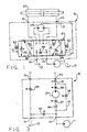
- FIG. 3 is a unidirectional flow diagram illustrating the fluid controller shown schematically in FIG. 1, as well as the various orifices shown in FIG. 1, and including the teachings of the present invention.
- FIG. 4 is an overlay view of the valving used in the fluid controller shown in FIG. 2, but on a larger scale than in FIG. 2, and with the valving shown in the neutral position.
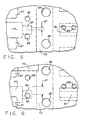
- FIGS. 5-7 are enlarged, fragmentary overlay views, similar to FIG. 4, but with the valving displaced from the neutral position.
- FIG. 8 is a graph of flow versus valve displacement, showing the main fluid path and the amplification fluid path of the present invention.
- FIG. 1 is a hydraulic schematic of a vehicle hydrostatic steering system including a fluid controller made in accordance with the teachings of the present invention.
- the system includes a fluid pump 11, shown herein as a fixed displacement pump, having its inlet connected to a system reservoir 13.
- the output of the pump 11 is directed to the hydrostatic steering system, and more specifically, to a fluid controller 15.
- the fluid controller 15 includes an inlet port 17, a return port 19, and a pair of control (cylinder) fluid ports 21 and 23, which are connected to the opposite ends of a steering cylinder 25.
- the fluid controller 15 which will be described in greater detail in conjunction with FIG. 2, may be of the general type illustrated and described in U.S. Patent No. Re. 25,126, assigned to the assignee of the present invention and incorporated herein by reference. More specifically, the controller 15 is of the open-center type. Disposed within the controller 15 is a valving arrangement, generally designated 27, which is movable from its neutral position shown in FIG. 1 to either a right turn position R or a left turn position L. When the valving arrangement 27 is in either of the turn positions, the pressurized fluid flowing through the valving 27 also flows through a fluid meter 29, one function of which is to measure (meter) the proper amount of fluid to be communicated to the appropriate control port 21 or 23.
- the other function of the fluid meter 29 is to provide follow-up movement to the valving 27, such that the valving 27 is returned to its neutral position after the desired amount of fluid has been communicated to the steering cylinder 25.
- this follow-up movement is achieved by means of a mechanical follow-up connection, indicated schematically at 31.
- the valving 27 defines a plurality of variable orifices whenever the valving is moved from its neutral position to one of its operating positions, either a right turn position R or a left turn position L.
- variable orifices will be described in greater detail subsequently in conjunction with the detailed description of FIGS. 3 and 4.
- the controller 15 comprises several sections, including a housing section 33, a port plate 35, a section comprising the fluid meter 29, and an end plate 37. These sections are held together in tight, sealing engagement by means of a plurality of bolts 39, which are in threaded engagement with the housing section 33.
- the housing section 33 defines the inlet port 17, the return port 19, and the control ports 21 and 23.
- the valving 27 comprises a primary, rotatable valve member 43 (hereinafter referred to as the "spool"), and a cooperating, relatively rotatable follow-up valve member 45 (hereinafter referred to as the "sleeve").
- spool a primary, rotatable valve member 43
- sleeve a cooperating, relatively rotatable follow-up valve member 45
- At the forward end of the spool 43 is a portion having a reduced diameter and defining a set of internal splines 47 which provide for a direct mechanical connection between the spool 43 and a steering wheel (not shown).
- the spool 43 and sleeve 45 will be described in greater detail subsequently.
- the fluid meter 29 may be of the type well known in the art, and includes an internally-toothed ring 49, and an externally-toothed star 51.
- the star 51 defines a set of internal splines 53, and in splined engagement therewith is a set of external splines 55, formed at the rearward end of a drive shaft 57.
- the drive shaft 57 has a bifurcated forward end permitting driving connection between the shaft 57 and the sleeve 45, by means of a pin 59 passing through a pair of pin openings 61 in the spool 43.
- Such movement of the star 51 causes follow-up movement of the sleeve 45, by means of the drive shaft 57 and pin 59 (which comprise the follow-up connection 31 of FIG. 1), to maintain a particular relative displacement between the spool 43 and sleeve 45.
- the relative displacement between the spool 43 and sleeve 45 is dependent upon the steering load, i.e., the hydraulic pressure being communicated to the steering cylinder 25.
- a plurality of leaf springs 63 extend through an opening in the spool 45, biasing the sleeve 45 toward the neutral position, relative to the spool 43.
- the housing section 33 defines four annular chambers surrounding the spool 45, to provide fluid communication between the outer surface of the spool 45 and the various ports 17, 19, 21 and 23, the annular chambers being designated by the reference numeral of the respective port, accompanied by the letter "c".
- the toothed interaction of the star 51, orbiting and rotating within the ring 49, defines a plurality of expanding and contracting fluid volume chambers, and adjacent each chamber, the port plate 35 defines a fluid port (not shown in FIG. 2).
- the housing section 33 provides a plurality of axial bores (not shown in FIG. 2), each of which is in open communication at one end with one of the fluid ports and one of the volume chambers and, at its other end, with the valve bore 41.
- the sleeve 45 defines a plurality of pressure ports 65, in communication with the annular chamber 17c.
- a plurality of meter ports 67 which communicate between the valving arrangement 27 and the expanding and contracting volume chambers of the fluid meter 29.
- a plurality of cylinder ports 69 Disposed to the left of the meter ports 67 is a plurality of cylinder ports 69, in communication with the annular chamber 23c, and further to the left, a plurality of cylinder ports 71, in communication with the annular chamber 21c.
- the spool 43 defines an annular groove 73, and in communication therewith, a plurality of axial slots 75. Circumferentially displaced from each of the axial slots 75 is a longer axial slot 77, and circumferentially aligned with each of the axial slots 75 is an even longer axial slot 79, the function of which will be described subsequently.
- the spool 43 defines a plurality of axial, open-center slots 81, each of which is in open communication, toward its right end, with the interior of the spool 43.
- the sleeve 45 defines a plurality of pairs of open-center holes 83.
- inlet fluid is communicated from the inlet port 17 into the annular chamber 17c.
- Both the pressure ports 65 and the pairs of open-center holes 83 are in open communication with the annular chamber 17c, but flow through the pressure ports 65 and into the annular groove 73 does not occur, because the axial slots 75 are blocked from communication with the meter ports 67, in the neutral position shown in FIG. 4. Instead, inlet fluid flows from the annular chamber 17c through the open-center holes 83 and into the respective open-center slot 81.
- Each of the slots 81 is in open communication with the interior of the spool, as mentioned previously, and the interior of the spool is in open, relatively unrestricted fluid communication with the system reservoir 13 by means of the annular chamber 19c and return port 19. Therefore, in an open-center controller, with the valving in the neutral position shown in FIG. 4, the inlet fluid is not pressurized, i.e., the pressure of the inlet fluid is only slightly greater than the pressure in the system reservoir 13.
- each pair of open-center holes 83, and the respective open-center slot 81 defines a variable orifice, having its maximum flow area when the valving is in neutral, the composite of these individual orifices comprising a variable neutral flow control orifice 85 (see FIGS. 1 and 3).
- every other meter port 67 begins to communicate with the adjacent axial slot 75, such that inlet fluid now begins to flow through the pressure ports 65 into the annular groove 73, then through the axial slots 75 and into these meter ports 67.
- Each pressure port 65 defines a fixed orifice, the composite of these individual orifices comprising a fixed flow control orifice 86 (see FIGS. 1 and 2).
- the inlet fluid flows from these meter ports 67 to the expanding volume chambers of the meter 29.
- fluid flows from the contracting volume chambers of the meter 29 back to the remaining, alternate meter ports 67, which are just beginning to communicate with the axial slots 77.
- each of the axial slots 75 and every other meter port 67 define a variable orifice, the composite of these individual variable orifices comprising a variable flow control orifice 87 (see FIG. 3).
- the communication between the alternate meter ports 67 and the axial slots 77 defines a variable orifice, the composite of these individual variable orifices comprising a variable flow control orifice 89.
- the variable orifice 87 is also frequently referred to as the A2 orifice, while the variable orifice 89 is frequently referred to as the A3 orifice.
- variable orifices 87 and 89 are beginning to open, the flow area of the neutral flow control orifice 85 is beginning to decrease, such that the pressure of the inlet fluid begins to increase.
- each axial slot 77 begins to communicate with its respective cylinder port 69, the communication therebetween defining a variable orifice.
- the composite of these individual variable orifices comprises a variable flow control orifice 91 (see FIGS. 1 and 3).
- the flow control orifice 91 is also frequently referred to as the A4 orifice.
- each of the axial slots 79 begins to communicate with its respective cylinder port 71, the communication therebetween defining a variable orifice.
- the composite of these individual variable orifices comprises a variable flow control orifice 93 (see FIGS. 1 and 3).
- the flow control orifice 93 is also frequently referred to as the A5 orifice.
- controller 15 have the particular arrangement of flow control orifices described hereinabove.
- the sleeve 45 defines a plurality of pairs of amplification bores 95.
- the bores 95 in each pair are centered with respect to an extension 97, which is in communication with the right end of the axial slot 77 in FIG. 4.
- one of each of the pairs of amplification bores 95 begins to communicate with the extension 97, and therefore, with the axial slot 77.
- the communication between each amplification bore 95, and its respective extension 97 defines a variable orifice, the composite of these individual orifices comprising a variable amplification orifice 99 (see FIG. 3).
- the variable amplification orifice 99 begins to open at substantially the same time as the variable flow control orifices 87 and 89, for reasons which will be apparent to those skilled in the art.
- amplification fluid path 101 (see FIG. 3), which includes the variable amplification orifice 99.
- the amplification fluid path 101 is in communication with the main fluid path at a location upstream of the fixed orifice 86.
- the fluid flowing through the amplification fluid path 101 then recombines with the main fluid path at a location downstream of the variable flow control orifice 89, but upstream of the variable flow control orifice 91. It will be understood by those skilled in the art that, when utilizing the present invention, it is necessary to increase the flow capacity of variable flow control orifices 91 and 93 to accommodate the total flow through both the main fluid path and the amplification fluid path.
- the spool 43 has been displaced, relative to the sleeve 45, by about 7 degrees which, in the subject embodiment, would constitute a normal "operating position".
- one of each pair of the amplification bores 95 is in complete communication with the extension 97, such that the variable amplification orifice 99 has now reached its maximum flow area.
- the communication between the open-center holes 83 and the open-center slots 81 is greatly reduced, such that the neutral flow control orifice 85 is approaching its minimum flow area, which typically would be a zero flow, or closed position.
- the graph of FIG. 8 it may be seen that the flow through the amplification fluid path 101 has reached its peak at the position shown in FIG.
- the reason for closing the variable amplification orifice 99 before the spool and sleeve reach maximum displacement is to permit operation of the controller 15 in the manual steering mode.
- manual rotation of the steering wheel rotates the star 51 of the fluid meter 29, causing the meter to function as a hand pump, and generate pressurized fluid to actuate the steering cylinder.
- the amplification fluid path is not able to serve as a "short-circuit", which would make it practically impossible to generate sufficient pressure to steer the vehicle. See co-pending EP-A-0 362 534.
- the flow through the main flow path designated "87" is nearly the same as the flow through the amplification fluid path 101, until approximately 5 or 6 degrees of displacement between the spool 43 and sleeve 45.
- the flow restriction through the amplification fluid path 101 is substantially identical to the flow restriction through the series combination of the variable orifice 87, the fluid meter 29, and the variable orifice 89. If those two flow restrictions are equal, the result is an amplification ratio of 2:1, i.e., the total flow out of the control fluid port (21 or 23) is twice the flow through the main fluid path. It is also possible, and would be within the ability of those skilled in the art, to vary the relationship between the flow restrictions of the amplification fluid path and main fluid path to provide an amplification ratio other than 2:1.
Landscapes
- Engineering & Computer Science (AREA)
- Chemical & Material Sciences (AREA)
- Combustion & Propulsion (AREA)
- Transportation (AREA)
- Mechanical Engineering (AREA)
- Power Steering Mechanism (AREA)
Claims (13)
- Steuergerät (15) mit offener Mittelstellung zum Steuern des Fluidstromes von einer Fluidquelle (11) zu einer fluiddruckbetätigten Vorrichtung (25); wobei das Steuergerät versehen ist mit einer Gehäuseanordnung (33), die einen Fluideinlaß (17) zum Anschluß an die Fluidquelle, einen Rückführanschluß (19) zur Verbindung mit einem Speicherbehälter (1.3) sowie einen ersten (23) und einen zweiten (21) Steuerfluidanschluß zur Verbindung mit der fluiddruckbetätigten Vorrichtung bildet; und einer Ventilanordnung (27), die in der Gehäuseanordnung untergebracht ist und eine Neutralstellung (Fig. 4) und eine erste Arbeitsstellung (Fig. 6) bildet; wobei die Gehäuseanordnung und die Ventilanordnung zusammen eine neutrale Fluidwegverbindung zwischen dem Fluideinlaß und dem Rückführanschluß bestimmen und eine verstellbare Neutralöffnung (85) aufweisen, die ihren größten Strömungsquerschnitt hat, wenn die Ventilanordnung in der Neutralstellung steht, und deren Strömungsquerschnitt abnimmt, wenn die Ventilanordnung von der Neutralstellung in Richtung auf die erste Arbeitsstellung verstellt wird; wobei die Gehäuseanordnung und die Ventilanordnung zusammen einen Hauptfluidweg (86, 87, 29, 89, 91, 93) bilden, der eine Verbindung zwischen dem Fluideinlaß und dem ersten Steuerfluidlanschluß sowie zwischen dem zweiten Steuerfluidanschluß und dem Rückführanschluß herstellt, wenn die Ventilanordnung in der ersten Arbeitsstellung steht; sowie ferner mit einer fluidbetätigten Anordnung (29), welche die Ventilanordnung zu einer Nachlaufbewegung veranlaßt, die proportional zu dem Volumen des Fluidstromes durch die fluidbetätigte Anordnung ist, wobei die fluidbetätigte Anordnung in dem ersten Hauptfluidweg strömungsmäßig in Reihe zwischen dem Fluideinlaß und dem ersten Steuerfluidanschluß liegt; wobei der Hauptfluidweg eine zwischen dem Fluideinlaß und der fluidbetätigten Anordnung befindliche feste Durchflußsteueröffnung (86) und eine zwischen der fluidbetätigten Anordnung und dem ersten Steuerfluidanschluß befindliche verstellbare Durchflußsteueröffnung (91) aufweist, wobei die verstellbare Durchflußsteueröffnung ihren kleinsten Strömungsquerschnitt hat, wenn die Ventilanordnung in der Neutralstellung steht, und einen zunehmenden Strömungsquerschnitt aufweist, wenn die Ventilanordnung von der Neutralstellung in Richtung auf die erste Arbeitsstellung verstellt wird; dadurch gekennzeichnet, daß:(a) die Gehäuseanordnung (33) und die Ventilanordnung (27) zusammen einen parallel zu dem Hauptfluidweg (86, 87, 29, 89, 91, 93) liegenden Verstärkungsfluidweg (101) bilden, der mit dem Hauptfluidweg an einer zwischen dem Fluideinlaß (17) und der festen Durchflußsteueröffnung (86) liegenden ersten Stelle sowie einer stromaufwärts von der verstellbaren Durchflußsteueröffnung (91) liegenden zweiten Stelle in Strömungsverbindung steht;(b) der Verstärkungsfluidweg (101) eine verstellbare Verstärkungsöffnung (99) aufweist, die ihren kleinsten Strömungsquerschnitt hat, wenn die Ventilanordnung (27) in der Neutralstellung steht, und deren Strömungsquerschnitt zunimmt, wenn die Ventilanordnung von der Neutralstellung in Richtung auf die erste Arbeitsstellung verstellt wird; und(c) die verstellbare Verstärkungsöffnung (99) sich zu öffnen beginnt, bevor sich die verstellbare Durchflußsteueröffnung (91) zu öffnen beginnt, wobei die verstellbare Verstärkungsöffnung ihren größten Strömungsquerschnitt hat, wenn die Ventilanordnung (27) in der ersten Arbeitsstellung (Fig. 6) steht, und der Strömungsquerschnitt der verstellbaren Verstärkungsöffnung abnimmt, wenn die Ventilanordnung von der ersten Arbeitsstellung in Richtung auf eine Stellung maximaler Verdrängung (Fig. 7) verstellt wird, wobei die verstellbare Verstärkungsöffnung geschlossen wird, bevor die Ventilanordnung die Stellung maximaler Verdrängung erreicht.
- Steuergerät mit offener Mittelstellung nach Anspruch 1, dadurch gekennzeichnet, daß der Hauptfluidweg eine zwischen der festen Durchflußsteueröffnung (86) und der fluidbetätigten Anordnung (29) sitzende zweite verstellbare Durchflußsteueröffnung (87) sowie eine dritte verstellbare Durchflußsteueröffnung (89) aufweist, die zwischen der fluidbetätigten Anordnung und dem ersten Steuerfluidanschluß (23) angeordnet ist, wobei die zweite und die dritte verstellbare Durchflußsteueröffnung ihren kleinsten Strömungsquerschnitt haben, wenn die Ventilanordnung (27) in der Neutralstellung steht, und der Strömungsquerschnitt der zweiten und der dritten verstellbaren Durchflßsteueröffnung zunimmt, wenn die Ventilanordnung von der Neutralstellung in Richtung auf die erste Arbeitsstellung verstellt wird; daß die zweite Verbindungsstelle zwischen dem Verstärkungsfluidweg (101) und dem Hauptfluidweg zwischen der dritten verstellbaren Durchflußsteueröffnung (89) und dem ersten Steuerfluidanschluß (23) liegt; und daß sich die verstellbare Verstärkungsöffnung (99) im wesentlichen zur gleichen Zeit zu öffnen beginnt, zu welcher sich die zweite und die dritte verstellbare Durchflußsteueröffnung (87, 89) zu öffnen beginnen.
- Steuergerät mit offener Mittelstellung nach Anspruch 1 oder 2, dadurch gekennzeichnet, daß die Ventilanordnung (27) ein drehbares Hauptventilorgan (43) und ein damit zusammenwirkendes, relativ drehbares Nachlaufventilorgan (45) aufweist, wobei das Hauptventilorgan und das Nachlaufventilorgan die Neutralstellung mit Bezug aufeinander bestimmen.
- Steuergerät mit offener Mittelstellung nach Anspruch 1, dadurch gekennzeichnet, daß das Haupt- und das Nachlaufventilorgan (43, 45) zusammen die verstellbare Neutralöffnung (85), die feste Durchflußsteueröffnung (86) und die verstellbare Durchflußsteueröffnung (91) bilden, wobei sich die Strömungsquerschnitte der verstellbaren Öffnungen in Abhängigkeit von der relativen Drehung des Haupt- und des Nachlaufventilorgans ändern.
- Steuergerät mit offener Mittelstellung nach Anspruch 2, dadurch gekennzeichnet, daß das Haupt- und das Nachlaufventilorgan (43, 45) zusammen auch die zweite und die dritte verstellbare Durchflußsteueröffnung (87, 89) bilden, wobei sich die Strömungsquerschnitte der zweiten und der dritten verstellbaren Durchflußsteueröffnung in Abhängigkeit von der relativen Drehung des Haupt- und des Nachlaufventilorgans ändern.
- Steuergerät mit offener Mittelstellung nach Anspruch 3, dadurch gekennzeichnet, daß der Verstärkungsfluidweg (101) und die verstellbare Verstärkungsöffnung (99) als Ganzes von dem Hauptventilorgan (43) und dem Nachlaufventilorgan (45) gebildet sind.
- Steuergerät mit offener Mittelstellung nach Anspruch 2, dadurch gekennzeichnet, daß die verstellbare Durchflußsteueröffnung (91) zwischen der dritten verstellbaren Durchflußsteueröffnung (89) und dem ersten Steuerfluidanschluß (23) sitzt.
- Steuergerät mit offener Mittelstellung nach Anspruch 7, dadurch gekennzeichnet, daß die zweite Stelle der Fluidverbindung zwischen dem Verstärkungsfluidweg (101) und dem Hauptfluidweg zwischen der verstellbaren Durchflußsteueröffnung (91) und der dritten verstellbaren Durchflußsteueröffnung (89) liegt.
- Steuergerät mit offener Mittelstellung nach Anspruch 3, dadurch gekennzeichnet, daß die fluidbetätigte Anordnung eine Fluiddosiervorrichtung (29) mit einem Dosierorgan (51) aufweist, das verstellbar ist, um das Volumen des durch den Hauptfluidweg (86, 87, 89) strömenden Fluids zu messen, wobei das Steuergerät ferner mit einer Anordnung (31; 57, 59) versehen ist, welche das Dosierorgan mit dem Nachlaufventilorgan (45) koppelt.
- Steuergerät mit offener Mittelstellung nach einem der vorhergehenden Ansprüche, dadurch gekennzeichnet, daß das Steuergerät ein im wesentlichen konstantes Verstärkungsverhältnis beim Verstellen der Ventilanordnung (27) von der Neutralstellung zu der ersten Arbeitsstellung (Fig. 6) und ein abnehmendes Verstärkungsverhältnis bei Bewegung der Ventilanordnung von der ersten Arbeitsstellung in Richtung auf die Stellung maximaler Verdrängung (Fig. 7) hat.
- Steuergerät mit offener Mittelstellung nach einem der vorhergehenden Ansprüche, dadurch gekennzeichnet, daß die Gehäuseanordnung (33) und die Ventilanordnung (27) zusammen einen zweiten Hauptfluidweg (Fig. 1, Linkskurvenfahrt) bilden, der eine Verbindung zwischen dem Fluideinlaß (17) und dem zweiten Steuerfluidanschluß (21) sowie zwischen dem ersten Steuerfluidanschluß (23) und dem Rückführanschluß (19) herstellt, wenn die Ventilanordnung in einer zweiten Arbeitsstellung steht.
- Steuergerät mit offener Mittelstellung nach Anspruch 11, dadurch gekennzeichnet, daß die Gehäuseanordnung (33) und die Ventilanordnung (27) zusammen einen parallel zu dem zweiten Hauptfluidweg liegenden zweiten Verstärkungsfluidweg bilden, der mit dem zweiten Hauptfluidweg an einer zwischen dem Fluideinlaß und der festen Durchflußsteueröffnung liegenden ersten Stelle und an einer zwischen einer dritten verstellbaren Durchflußsteueröffnung und dem zweiten Steuerfluidanschluß liegenden zweiten Stelle in Strömungsverbindung steht.
- Steuergerät mit offener Mittelstellung nach Anspruch 12, dadurch gekennzeichnet, daß der zweite Verstärkungsfluidweg eine zweite verstellbare Verstärkungsöffnung aufweist, die ihren kleinsten Strömungsquerschnitt hat, wenn die Ventilanordnung in der Neutralstellung steht, und deren Strömungsquerschnitt zunimmt, wenn die Ventilanordnung von der Neutralstellung in Richtung auf die zweite Arbeitsstellung verstellt wird, wobei sich die zweite verstellbare Verstärkungsöffnung im wesentlichen zur gleichen Zeit zu öffnen beginnt, zu welcher sich die dritte verstellbare Durchflußsteueröffnung zu öffnen beginnt.
Applications Claiming Priority (2)
| Application Number | Priority Date | Filing Date | Title |
|---|---|---|---|
| US325721 | 1989-03-20 | ||
| US07/325,721 US4958493A (en) | 1988-10-06 | 1989-03-20 | Open-center steering control unit with flow amplification |
Publications (2)
| Publication Number | Publication Date |
|---|---|
| EP0388711A1 EP0388711A1 (de) | 1990-09-26 |
| EP0388711B1 true EP0388711B1 (de) | 1992-12-02 |
Family
ID=23269137
Family Applications (1)
| Application Number | Title | Priority Date | Filing Date |
|---|---|---|---|
| EP90104382A Expired - Lifetime EP0388711B1 (de) | 1989-03-20 | 1990-03-07 | Steuereinheit für eine Lenkung mit Durchflussverstärkung und offener Mitte |
Country Status (4)
| Country | Link |
|---|---|
| US (1) | US4958493A (de) |
| EP (1) | EP0388711B1 (de) |
| JP (1) | JP2852448B2 (de) |
| DE (1) | DE69000508T2 (de) |
Families Citing this family (22)
| Publication number | Priority date | Publication date | Assignee | Title |
|---|---|---|---|---|
| US5136844A (en) * | 1990-10-11 | 1992-08-11 | Eaton Corportaion | Controller with reduced travel limit slip |
| US5596498A (en) * | 1994-01-14 | 1997-01-21 | Danfoss A/S | Hydraulic steering arrangement for vehicles |
| DE19503331C1 (de) * | 1995-02-02 | 1996-08-08 | Hydraulik Nord Gmbh | Hydraulische Lenkeinrichtung mit Stromverstärkung |
| US5638864A (en) * | 1995-11-22 | 1997-06-17 | Eaton Corporation | Steering control unit with flow amplification for unequal area cylinder |
| ES2121457T3 (es) * | 1996-11-02 | 1998-11-16 | Hydraulik Nord Gmbh | Mecanismo hidraulico de direccion con variacion de la transmision e intensificacion de corriente. |
| US6071102A (en) | 1997-05-28 | 2000-06-06 | Eaton Corporation | Floating seal for sealed star gerotor |
| US5819532A (en) * | 1997-06-06 | 1998-10-13 | Eaton Corporation | Dynamic load signal fluid controller with instant on flow amplification |
| ES2216324T3 (es) | 1997-09-29 | 2004-10-16 | Zf Lemforder Metallwaren Ag | Motor oscilante radial. |
| US6122912A (en) * | 1997-10-16 | 2000-09-26 | Techco Corporation | Electro-hydraulic power steering systems having improved efficiency |
| US6244158B1 (en) | 1998-01-06 | 2001-06-12 | Fps, Inc. | Open center hydraulic system with reduced interaction between branches |
| US7283900B1 (en) * | 2006-03-14 | 2007-10-16 | Deere & Company | Work vehicle steering system with flow-metering curve selection and associated method |
| US7913800B2 (en) * | 2006-10-30 | 2011-03-29 | Deere & Company | Steering system with variable flow rate amplification ratio and associated method |
| CN101255880B (zh) * | 2007-12-10 | 2010-06-02 | 兰州理工大学 | 中位卸荷型流量放大阀 |
| EP2127998A1 (de) * | 2008-05-30 | 2009-12-02 | Sauer-Danfoss Holding ApS | Hydraulische Lenkeinheit |
| EP2610139A1 (de) | 2011-12-28 | 2013-07-03 | Sauer-Danfoss ApS | Hydraulische Lenkeinheit |
| DE102017109795B4 (de) * | 2017-05-08 | 2019-01-24 | Danfoss Power Solutions Aps | Hydraulische Lenkeinheit |
| DE102017109794B4 (de) | 2017-05-08 | 2019-05-09 | Danfoss Power Solutions Aps | Hydraulische Lenkeinheit |
| DE102017109803B4 (de) | 2017-05-08 | 2019-01-31 | Danfoss Power Solutions Aps | Hydraulische Lenkeinheit |
| DE102017109800B4 (de) * | 2017-05-08 | 2019-01-24 | Danfoss Power Solutions Aps | Hydraulische Lenkeinheit |
| DE102017109801B4 (de) * | 2017-05-08 | 2019-02-07 | Danfoss Power Solutions Aps | Hvdraulische Lenkeinheit |
| DE102017109798B4 (de) * | 2017-05-08 | 2018-12-27 | Danfoss Power Solutions Aps | Hydraulische Lenkeinheit |
| DE102018125053B4 (de) * | 2018-10-10 | 2022-02-17 | Danfoss Power Solutions Aps | Hydraulische Lenkanordnung |
Family Cites Families (19)
| Publication number | Priority date | Publication date | Assignee | Title |
|---|---|---|---|---|
| DE1755297C3 (de) * | 1968-04-23 | 1979-11-08 | Danfoss A/S, Nordborg (Daenemark) | Hydrostatische Hilfskraftlenkeinrichtung, insbesondere für schwere Fahrzeuge |
| DE1755387C3 (de) * | 1968-05-03 | 1973-11-08 | Danfoss A/S, Nordborg (Daenemark) | Hydrostatische Lenkeinrichtung, insbesondere fur schwere Fahrzeuge |
| US3707200A (en) * | 1970-12-28 | 1972-12-26 | Caterpillar Tractor Co | Dual meter unit steering control |
| DE2305798C3 (de) * | 1973-02-07 | 1975-09-18 | Danfoss A/S, Nordborg (Daenemark) | Hydraulische Steuereinrichtung für einen Servomotor, insbesondere für Fahrzeuglenkungen |
| US4037620A (en) * | 1976-04-23 | 1977-07-26 | Eaton Corporation | Controller for fluid pressure operated devices |
| US4109679A (en) * | 1976-04-23 | 1978-08-29 | Eaton Corporation | Controller for fluid pressure operated devices |
| US4096883A (en) * | 1976-08-24 | 1978-06-27 | Eaton Corporation | Closed-center controller and neutral bypass arrangement therefor |
| US4167893A (en) * | 1978-02-06 | 1979-09-18 | Eaton Corporation | Load sensing valve |
| US4212229A (en) * | 1978-10-25 | 1980-07-15 | Eaton Corporation | Controller for fluid pressure operated devices |
| AU568946B2 (en) * | 1984-08-08 | 1988-01-14 | Bishop Steering Technology Limited | Power steering control valve |
| US4640094A (en) * | 1986-02-04 | 1987-02-03 | Deere & Company | Flow amplifying steering system |
| US4781219A (en) * | 1986-10-10 | 1988-11-01 | Eaton Corporation | Fluid controller and dampening fluid path |
| JP2525400B2 (ja) * | 1987-03-26 | 1996-08-21 | 豊田工機株式会社 | 動力舵取装置用サ−ボ弁装置 |
| JPH0818571B2 (ja) * | 1987-06-29 | 1996-02-28 | 日産自動車株式会社 | パワ−ステアリングの油圧制御装置 |
| US4759182A (en) * | 1987-07-24 | 1988-07-26 | Eaton Corporation | Steering control unit with flow amplification |
| US4827978A (en) * | 1988-10-03 | 1989-05-09 | Eaton Corporation | Fluid controller with reduced steering wheel precession |
| US4862690A (en) * | 1988-10-06 | 1989-09-05 | Eaton Corporation | Steering control unit with both flow amplification and manual steering capability |
| US4838314A (en) * | 1988-10-12 | 1989-06-13 | Deere & Company | Secondary hydraulic steering system |
| JP2659097B2 (ja) * | 1988-12-20 | 1997-09-30 | 住友イートン機器株式会社 | 全油圧式パワーステアリング装置 |
-
1989
- 1989-03-20 US US07/325,721 patent/US4958493A/en not_active Ceased
-
1990
- 1990-03-07 DE DE9090104382T patent/DE69000508T2/de not_active Expired - Fee Related
- 1990-03-07 EP EP90104382A patent/EP0388711B1/de not_active Expired - Lifetime
- 1990-03-19 JP JP2069534A patent/JP2852448B2/ja not_active Expired - Fee Related
Also Published As
| Publication number | Publication date |
|---|---|
| EP0388711A1 (de) | 1990-09-26 |
| JPH02267076A (ja) | 1990-10-31 |
| JP2852448B2 (ja) | 1999-02-03 |
| DE69000508T2 (de) | 1993-04-15 |
| DE69000508D1 (de) | 1993-01-14 |
| US4958493A (en) | 1990-09-25 |
Similar Documents
| Publication | Publication Date | Title |
|---|---|---|
| EP0388711B1 (de) | Steuereinheit für eine Lenkung mit Durchflussverstärkung und offener Mitte | |
| EP0300269B1 (de) | Lenkungssteuereinheit mit Strömungsverstärkung | |
| EP0038542B1 (de) | Druckmittelbetätigtes Steuergerät | |
| EP1153818B1 (de) | Durchflussregler mit Dosierpumpen-Umgehungsleitung | |
| US4781219A (en) | Fluid controller and dampening fluid path | |
| US3931711A (en) | Controller assembly | |
| EP0362534B1 (de) | Lenkungssteuereinheit mit Strömungsverstärkung und Handsteuermöglichkeit | |
| US4804016A (en) | Fluid controller with improved pressure balancing | |
| EP0502456B1 (de) | Flüssigkeitssteuerung mit lastgesteuerter Priorität-Durchflussregelmöglichkeit | |
| US5620026A (en) | Fluid controller and improved backflow prevention therefor | |
| USRE34746E (en) | Open-center steering control unit with flow amplification | |
| EP0535556B1 (de) | Flüssigkeitssteuerung und verbesserte Rückschlagventileinrichtung dafür | |
| US4558720A (en) | Closed-center controller for use with unequal area cylinder | |
| EP0775623B1 (de) | Lenkungssteuereinheit mit Stromverstärkung für ungleiche Kolbenflächen | |
| EP0567859B1 (de) | Fluidregler mit veränderlichen zusätzlichen Steuerfunktionen | |
| US6769451B2 (en) | Power beyond steering unit with bypass | |
| EP1020343B1 (de) | Lastreaktive Lenkeinheit für Lenkzylinder mit ungleichen Flächen | |
| EP0264613B1 (de) | Flüssigkeitssteuerung und gedämpfter Flüssigkeitsweg | |
| EP1262393B1 (de) | Lenksystem mit geringer Lenk-Abweichung und verbessertem Fluid-Regler dafür | |
| EP0835798B1 (de) | Lenksteuereinrichtung | |
| US3957129A (en) | Steering system | |
| US7490626B2 (en) | Steer valve with hydraulic vehicle position feedback |
Legal Events
| Date | Code | Title | Description |
|---|---|---|---|
| PUAI | Public reference made under article 153(3) epc to a published international application that has entered the european phase |
Free format text: ORIGINAL CODE: 0009012 |
|
| AK | Designated contracting states |
Kind code of ref document: A1 Designated state(s): DE FR GB IT |
|
| 17P | Request for examination filed |
Effective date: 19901210 |
|
| 17Q | First examination report despatched |
Effective date: 19910618 |
|
| GRAA | (expected) grant |
Free format text: ORIGINAL CODE: 0009210 |
|
| AK | Designated contracting states |
Kind code of ref document: B1 Designated state(s): DE FR GB IT |
|
| ITF | It: translation for a ep patent filed | ||
| REF | Corresponds to: |
Ref document number: 69000508 Country of ref document: DE Date of ref document: 19930114 |
|
| ET | Fr: translation filed | ||
| PLBE | No opposition filed within time limit |
Free format text: ORIGINAL CODE: 0009261 |
|
| STAA | Information on the status of an ep patent application or granted ep patent |
Free format text: STATUS: NO OPPOSITION FILED WITHIN TIME LIMIT |
|
| 26N | No opposition filed | ||
| REG | Reference to a national code |
Ref country code: GB Ref legal event code: IF02 |
|
| PGFP | Annual fee paid to national office [announced via postgrant information from national office to epo] |
Ref country code: GB Payment date: 20050207 Year of fee payment: 16 |
|
| PGFP | Annual fee paid to national office [announced via postgrant information from national office to epo] |
Ref country code: FR Payment date: 20050302 Year of fee payment: 16 |
|
| PGFP | Annual fee paid to national office [announced via postgrant information from national office to epo] |
Ref country code: DE Payment date: 20050331 Year of fee payment: 16 |
|
| PG25 | Lapsed in a contracting state [announced via postgrant information from national office to epo] |
Ref country code: GB Free format text: LAPSE BECAUSE OF NON-PAYMENT OF DUE FEES Effective date: 20060307 |
|
| PGFP | Annual fee paid to national office [announced via postgrant information from national office to epo] |
Ref country code: IT Payment date: 20060331 Year of fee payment: 17 |
|
| PG25 | Lapsed in a contracting state [announced via postgrant information from national office to epo] |
Ref country code: DE Free format text: LAPSE BECAUSE OF NON-PAYMENT OF DUE FEES Effective date: 20061003 |
|
| GBPC | Gb: european patent ceased through non-payment of renewal fee |
Effective date: 20060307 |
|
| REG | Reference to a national code |
Ref country code: FR Ref legal event code: ST Effective date: 20061130 |
|
| PG25 | Lapsed in a contracting state [announced via postgrant information from national office to epo] |
Ref country code: FR Free format text: LAPSE BECAUSE OF NON-PAYMENT OF DUE FEES Effective date: 20060331 |
|
| PG25 | Lapsed in a contracting state [announced via postgrant information from national office to epo] |
Ref country code: IT Free format text: LAPSE BECAUSE OF NON-PAYMENT OF DUE FEES Effective date: 20070307 |