EP0388879A2 - Extensomètre hermétique - Google Patents
Extensomètre hermétique Download PDFInfo
- Publication number
- EP0388879A2 EP0388879A2 EP90105220A EP90105220A EP0388879A2 EP 0388879 A2 EP0388879 A2 EP 0388879A2 EP 90105220 A EP90105220 A EP 90105220A EP 90105220 A EP90105220 A EP 90105220A EP 0388879 A2 EP0388879 A2 EP 0388879A2
- Authority
- EP
- European Patent Office
- Prior art keywords
- section
- mounting
- stud
- strain
- walls
- Prior art date
- Legal status (The legal status is an assumption and is not a legal conclusion. Google has not performed a legal analysis and makes no representation as to the accuracy of the status listed.)
- Withdrawn
Links
Images


Classifications
-
- G—PHYSICS
- G01—MEASURING; TESTING
- G01L—MEASURING FORCE, STRESS, TORQUE, WORK, MECHANICAL POWER, MECHANICAL EFFICIENCY, OR FLUID PRESSURE
- G01L5/00—Apparatus for, or methods of, measuring force, work, mechanical power, or torque, specially adapted for specific purposes
- G01L5/04—Apparatus for, or methods of, measuring force, work, mechanical power, or torque, specially adapted for specific purposes for measuring tension in flexible members, e.g. ropes, cables, wires, threads, belts or bands
- G01L5/10—Apparatus for, or methods of, measuring force, work, mechanical power, or torque, specially adapted for specific purposes for measuring tension in flexible members, e.g. ropes, cables, wires, threads, belts or bands using electrical means
- G01L5/106—Apparatus for, or methods of, measuring force, work, mechanical power, or torque, specially adapted for specific purposes for measuring tension in flexible members, e.g. ropes, cables, wires, threads, belts or bands using electrical means for measuring a reaction force applied on a cantilever beam
-
- G—PHYSICS
- G01—MEASURING; TESTING
- G01L—MEASURING FORCE, STRESS, TORQUE, WORK, MECHANICAL POWER, MECHANICAL EFFICIENCY, OR FLUID PRESSURE
- G01L5/00—Apparatus for, or methods of, measuring force, work, mechanical power, or torque, specially adapted for specific purposes
- G01L5/04—Apparatus for, or methods of, measuring force, work, mechanical power, or torque, specially adapted for specific purposes for measuring tension in flexible members, e.g. ropes, cables, wires, threads, belts or bands
- G01L5/10—Apparatus for, or methods of, measuring force, work, mechanical power, or torque, specially adapted for specific purposes for measuring tension in flexible members, e.g. ropes, cables, wires, threads, belts or bands using electrical means
-
- G—PHYSICS
- G01—MEASURING; TESTING
- G01L—MEASURING FORCE, STRESS, TORQUE, WORK, MECHANICAL POWER, MECHANICAL EFFICIENCY, OR FLUID PRESSURE
- G01L5/00—Apparatus for, or methods of, measuring force, work, mechanical power, or torque, specially adapted for specific purposes
- G01L5/04—Apparatus for, or methods of, measuring force, work, mechanical power, or torque, specially adapted for specific purposes for measuring tension in flexible members, e.g. ropes, cables, wires, threads, belts or bands
- G01L5/10—Apparatus for, or methods of, measuring force, work, mechanical power, or torque, specially adapted for specific purposes for measuring tension in flexible members, e.g. ropes, cables, wires, threads, belts or bands using electrical means
- G01L5/108—Apparatus for, or methods of, measuring force, work, mechanical power, or torque, specially adapted for specific purposes for measuring tension in flexible members, e.g. ropes, cables, wires, threads, belts or bands using electrical means for measuring a reaction force applied on a single support, e.g. a glider
Definitions
- This invention relates to a rugged device for measuring tension in a traveling threadline wherein the device is immune to corrosive environments and the measurement is independent of the location of the application of forces on the sensing element of the device.
- EP-A-299,738 discloses a tensiometer for moving threadlines wherein the theadline can be located within a small but flat, ungrooved, area.
- the Richards device utilizes twin beams of varying thickness positioned inside of two outer shells. Strain gages are attached directly to the beams at locations of minimum thickness. Although the beams are enveloped in two shells, the strain gages are not sealed from the effects of a hostile or corrosive atmosphere.
- the present invention provides a force measuring device with a body and a strain gage cartridge wherein the body comprises a mounting end, a moving end, upper and lower flexing walls, and an inflexible hollow core; and the strain gage cartridge comprises a mounting section, a stud section, and a strain measuring section.
- the upper and lower flexing walls of the body each have a front end and a back end, with: (i) each front end fixed to the mounting end of the body, (ii) each back end fixed to the moving end of the body, and (iii) the walls spaced apart and parallel with each other.
- the inflexible hollow core is fixed to the mounting end of the body and extends into the body, between the upper and lower walls.
- the core is not in contact with the moving end of the body.
- the mounting section of the strain gage cartridge is inflexibly affixed in the hollow core of the body, the stud section is affixed to the moving end of the body in a way to prevent relative transverse movement, and the strain measuring section is joined, at one end, with the mounting section and, at the other end, with the stud section.
- the device of this invention finds use in measuring the tension on moving threadlines and, in that use, the device can have, additionally, a direction-changing contact surface affixed to the force application section of the strain gage cartridge; and that direction-changing contact surface can be affixed on the axis with the device or at an angle therewith. Arms and other rigid linkages can, also, be affixed to the force application section of the strain gage cartridge, permitting measurement of forces applied remote from the device and at a variety of angles with the axis of the device.
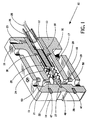
- Fig. 1 shows the force measuring device 10 of this invention with body 11 and strain gage cartridge 12 affixed thereto.
- the body 11 includes a mounting end 13 and a moving end 14, along with a flexing upper wall 15 and a flexing lower wall 16.
- the body 11, also, includes inflexible hollow core 17 located between walls 15 and 16. Hollow core 17 is fixed to mounting end 13 and extends into the space bounded by mounting end 13, moving end 14, and walls 15 and 16. Inner face 21 of hollow core 17 is situated near to, but not touching inner face 22 of moving end 14.
- the body is conveniently of one-piece construction and is machined from 2024-351 aluminum alloy or high tensile stainless steel.
- Strain gage cartridge 12 includes a mounting section 18, a stud section 19, and a strain measuring section 20.
- the cartridge 12 is fixed in hollow core 17 of body 11 by, for example, at least one screw 23 screwed down on mounting section 18.
- Strain measuring section 20 has strain gages 24 appropriately mounted, with electrical leads 25 attached thereto and extending from cartridge 12 through sealed connector 26.
- Stud section 19 is affixed, at one end, to strain measuring section 20 and has, at the other end, stud 27. Stud 27 slip-fits info stud-receiving hole 28 in moving end 14 in such a way as to prevent transverse relative movement between stud section 19 and moving end 14.
- flexible protective cover 29 surrounds strain measuring section 20 and is sealed to stud section 19 and mounting section 18.
- Flexible protective cover 29 can be made from stainless steel or nickel or some equivalent material.
- channels 30 through mounting section 18 can be filled with an elastomer or other caulking to permit passage of leads 25 and isolate the strain measuring section 20.
- Spindle mounting block 40 is, typically fitted with ridge 41, mounting holes 42, and spindle mounting bracket 43.
- Spindle 44 is attached to spindle mounting block 40 by means of shaft 45 into spindle mounting bracket 43.
- Spindle mounting bracket 43 can be, for example, a pinch collar mounting.
- Direction-changing contact surface 46 is provided in this embodiment as a cylindrical surface around shaft 45, rotatably mounted or not.
- Spindle mounting block 40 is affixed to the outer face of moving end 14 by means of bolts (not shown) through holes 42 in the spindle mounting block 40 and into threaded holes 47 in moving end 14. To assure positive and unchanging location, ridge 41 of spindle mounting block 40 is fitted into channel 48 in moving end 14.
- threadline 49 is drawn over or pulled down upon direction-changing contact surface 46 and the force thereby exerted is transferred to the force measuring device of this invention.
- the range of motion is limited by means of adjustable stops 50, which can be turned to alter the amount of travel possible between moving end 14 and inflexible core 17.
- the limited motion is necessary for protection of the strain gages 24, specifically, and the strain gage cartridge 12, in general.
- Figs. 3a and 3b the force measuring device of this invention is shown in two different attitudes.
- Fig. 3a represents a complete embodiment of the force measuring device of this invention in an attitude without application of any force.
- the axes of body 11, strain gage cartridge 12, spindle mounting block 40, and spindle 44 form a single centerline CLa.
- Fig. 3b represents the same complete embodiment in an attitude with force applied to spindle 44.
- the deflection which is caused by application of the force is greatly exaggerated.
- Mounting end 13 of body 11 is rigidly fixed and is not moved by application of any forces F. Because mounting end 13 does not move, and because walls 15 and 16 are parallel, any force F causes a translation of the axis, and not a bending of the axis, through the center of the device. Any of forces F1, F2, or F3 cause a deflection of centerline CLb to CLb′ (a distance of c) and the centerlines remain parallel.
Landscapes
- Physics & Mathematics (AREA)
- General Physics & Mathematics (AREA)
- Force Measurement Appropriate To Specific Purposes (AREA)
- Cable Accessories (AREA)
- Measurement Of Force In General (AREA)
Applications Claiming Priority (2)
| Application Number | Priority Date | Filing Date | Title |
|---|---|---|---|
| US07/326,552 US4912983A (en) | 1989-03-20 | 1989-03-20 | Sealed tensiometer |
| US326552 | 1989-03-20 |
Publications (2)
| Publication Number | Publication Date |
|---|---|
| EP0388879A2 true EP0388879A2 (fr) | 1990-09-26 |
| EP0388879A3 EP0388879A3 (fr) | 1992-05-20 |
Family
ID=23272704
Family Applications (1)
| Application Number | Title | Priority Date | Filing Date |
|---|---|---|---|
| EP19900105220 Withdrawn EP0388879A3 (fr) | 1989-03-20 | 1990-03-20 | Extensomètre hermétique |
Country Status (4)
| Country | Link |
|---|---|
| US (1) | US4912983A (fr) |
| EP (1) | EP0388879A3 (fr) |
| JP (1) | JPH02285227A (fr) |
| CA (1) | CA2012189A1 (fr) |
Cited By (1)
| Publication number | Priority date | Publication date | Assignee | Title |
|---|---|---|---|---|
| EP0491151A1 (fr) * | 1990-11-22 | 1992-06-24 | Hottinger Baldwin Messtechnik Gmbh | Capteur de force pour la mesure de la tension des fils |
Families Citing this family (2)
| Publication number | Priority date | Publication date | Assignee | Title |
|---|---|---|---|---|
| DE10321890B4 (de) * | 2003-05-07 | 2005-10-27 | Bos Gmbh & Co. Kg | Befestigungsvorrichtung für einen Fahrzeugraum |
| CN106626503B (zh) * | 2016-12-27 | 2019-02-12 | 银川西部大森数控技术有限公司 | 一种可以实现直接测量力的内藏式力传感器 |
Family Cites Families (13)
| Publication number | Priority date | Publication date | Assignee | Title |
|---|---|---|---|---|
| US31312A (en) * | 1861-02-05 | Extension-table | ||
| CH353555A (de) * | 1956-04-06 | 1961-04-15 | Baldwin Lima Hamilton Corp | Kraftmesseinrichtung |
| US3280623A (en) * | 1964-04-10 | 1966-10-25 | Erwin J Saxl | Load cell for measurement of low forces |
| SE311573B (fr) * | 1967-02-08 | 1969-06-16 | Bofors Ab | |
| US3602866A (en) * | 1968-12-18 | 1971-08-31 | Erwin J Saxl | Force transducer |
| SE354120B (fr) * | 1970-04-14 | 1973-02-26 | Bofors Ab | |
| US3805604A (en) * | 1973-04-25 | 1974-04-23 | A Ormond | Load cell and flexure means for transferring force thereto |
| USRE31312E (en) | 1977-10-11 | 1983-07-19 | W. J. Industries, Inc. | Tension monitor means |
| US4326424A (en) * | 1979-03-30 | 1982-04-27 | Cleveland Machine Controls, Inc. | Web tension transducer arrangement |
| US4295360A (en) * | 1980-01-14 | 1981-10-20 | E. I. Du Pont De Nemours And Company | Tension measuring apparatus |
| FR2523304A1 (fr) * | 1982-03-09 | 1983-09-16 | Testut Aequitas | Dynamometre a poutre de flexion |
| US4821583A (en) * | 1987-07-14 | 1989-04-18 | E. I. Du Pont De Nemours And Company | Tension measuring apparatus |
| DE3824636A1 (de) * | 1988-07-20 | 1990-01-25 | Bizerba Werke Kraut Kg Wilh | Kraftaufnehmer, insbesondere fuer waagen |
-
1989
- 1989-03-20 US US07/326,552 patent/US4912983A/en not_active Expired - Lifetime
-
1990
- 1990-03-14 CA CA002012189A patent/CA2012189A1/fr not_active Abandoned
- 1990-03-15 JP JP2062826A patent/JPH02285227A/ja active Pending
- 1990-03-20 EP EP19900105220 patent/EP0388879A3/fr not_active Withdrawn
Cited By (2)
| Publication number | Priority date | Publication date | Assignee | Title |
|---|---|---|---|---|
| EP0491151A1 (fr) * | 1990-11-22 | 1992-06-24 | Hottinger Baldwin Messtechnik Gmbh | Capteur de force pour la mesure de la tension des fils |
| US5277072A (en) * | 1990-11-22 | 1994-01-11 | Hottinger Baldwin Messtechnik Gmbh | Device for measuring a force causing tensile stress in a thread |
Also Published As
| Publication number | Publication date |
|---|---|
| US4912983A (en) | 1990-04-03 |
| JPH02285227A (ja) | 1990-11-22 |
| CA2012189A1 (fr) | 1990-09-20 |
| EP0388879A3 (fr) | 1992-05-20 |
Similar Documents
| Publication | Publication Date | Title |
|---|---|---|
| US7516675B2 (en) | Joystick sensor apparatus | |
| US4478089A (en) | Tri-axial force transducer for a manipulator gripper | |
| US3602866A (en) | Force transducer | |
| US5317916A (en) | Digit grip sensor | |
| US3554025A (en) | Force measuring device | |
| CA1310514C (fr) | Appareil de mesure de tension | |
| US4099409A (en) | Multi-axis load cell with arcuate flexures | |
| US3180139A (en) | Force transducers | |
| US3805600A (en) | Transducer device and measurement systems | |
| EP0312761B1 (fr) | Appareil pour contrôler les dimensions linéaires de pièces | |
| US3722264A (en) | Transducer and components therefor | |
| US5228527A (en) | Force measurement assembly | |
| KR20240087657A (ko) | 관통 보어를 갖는 세장형 힘 센서 어셈블리 | |
| US4912983A (en) | Sealed tensiometer | |
| US4433586A (en) | Electronic cable load gauge | |
| US4597297A (en) | Tension measurement device | |
| US4241801A (en) | Apparatus to measure elongation due to bending under load | |
| CA2279769A1 (fr) | Detecteur de contrainte de compression | |
| EP0046692B1 (fr) | Dispositif de pesage pour un chariot élévateur à fourche | |
| US7437943B2 (en) | Force measurement element | |
| CA1054824A (fr) | Element de charge multi-axe | |
| JPH0229179B2 (ja) | Denshibakari | |
| US4580645A (en) | Constant moment weigh scale with misalignment compensator | |
| US4166998A (en) | Force transducer | |
| DE8700885U1 (de) | Tastkopf für Koordinatenmeßgeräte |
Legal Events
| Date | Code | Title | Description |
|---|---|---|---|
| PUAI | Public reference made under article 153(3) epc to a published international application that has entered the european phase |
Free format text: ORIGINAL CODE: 0009012 |
|
| AK | Designated contracting states |
Kind code of ref document: A2 Designated state(s): DE ES GB NL |
|
| 17P | Request for examination filed |
Effective date: 19901227 |
|
| PUAL | Search report despatched |
Free format text: ORIGINAL CODE: 0009013 |
|
| AK | Designated contracting states |
Kind code of ref document: A3 Designated state(s): DE ES GB NL |
|
| 17Q | First examination report despatched |
Effective date: 19930615 |
|
| STAA | Information on the status of an ep patent application or granted ep patent |
Free format text: STATUS: THE APPLICATION IS DEEMED TO BE WITHDRAWN |
|
| 18D | Application deemed to be withdrawn |
Effective date: 19931026 |