EP0389033A2 - Dispositif pour la génération d'une radiation X ou gamma à faible section et position variable - Google Patents
Dispositif pour la génération d'une radiation X ou gamma à faible section et position variable Download PDFInfo
- Publication number
- EP0389033A2 EP0389033A2 EP90200571A EP90200571A EP0389033A2 EP 0389033 A2 EP0389033 A2 EP 0389033A2 EP 90200571 A EP90200571 A EP 90200571A EP 90200571 A EP90200571 A EP 90200571A EP 0389033 A2 EP0389033 A2 EP 0389033A2
- Authority
- EP
- European Patent Office
- Prior art keywords
- diaphragm body
- diaphragm
- slots
- arrangement according
- slot
- Prior art date
- Legal status (The legal status is an assumption and is not a legal conclusion. Google has not performed a legal analysis and makes no representation as to the accuracy of the status listed.)
- Granted
Links
Images
Classifications
-
- G—PHYSICS
- G21—NUCLEAR PHYSICS; NUCLEAR ENGINEERING
- G21K—HANDLING OF PARTICLES OR IONISING RADIATION NOT OTHERWISE PROVIDED FOR; IRRADIATION DEVICES; GAMMA RAY OR X-RAY MICROSCOPES
- G21K1/00—Arrangements for handling particles or ionising radiation, e.g. focusing or moderating
- G21K1/02—Arrangements for handling particles or ionising radiation, e.g. focusing or moderating using diaphragms, collimators
- G21K1/04—Arrangements for handling particles or ionising radiation, e.g. focusing or moderating using diaphragms, collimators using variable diaphragms, shutters, choppers
- G21K1/043—Arrangements for handling particles or ionising radiation, e.g. focusing or moderating using diaphragms, collimators using variable diaphragms, shutters, choppers changing time structure of beams by mechanical means, e.g. choppers, spinning filter wheels
Definitions
- the invention relates to an arrangement for generating an X-ray or gamma ray with a small cross-section and changeable direction, with an X-ray or gamma ray, from the focus of which a beam of rays emanates, and a diaphragm arrangement which blocks a beam from the beam and a rotatable hollow cylindrical first diaphragm body with two circumferentially offset helical slots.
- the diaphragm body made of a radiation-absorbing material has the shape of a hollow cylinder, which is provided on its circumference with two circumferential, helically arranged slots. If a bundle of parallel rays falls on such a diaphragm body perpendicular to its cylinder axis, there is always a point at which an X-ray beam passes through the two slots. If the diaphragm body is rotated, this point moves along the axis, so that a periodically moving X-ray beam emerges behind the diaphragm body. This periodically moving X-ray beam can be used for medical or industrial examinations.
- An X-ray beam with a trapezoidal cross-section is defined by the two slits in the diaphragm body.
- a square or circular cross-section is desired, which means that the direction is independent pending spatial resolution results.
- the approximation to the square cross-sectional shape is better, the greater the angle at which the two slots intersect.
- a larger cutting angle could be achieved by using a diaphragm body with a large diameter and a small axial length.
- a relatively large deflection angle of the X-ray beam is required, which requires a corresponding axial length of the diaphragm body; a large diameter is undesirable in many applications because of the volume involved.
- the object of the present invention is to design an arrangement of the type mentioned at the outset in such a way that a favorable beam cross section is achieved even with a diaphragm body with a small diameter and a relatively large axial length.
- slots wind in at least one turn around the diaphragm body and are shaped such that at least one straight line runs through the slots towards the focus, the position of which can be changed by rotating the diaphragm body.
- the slots in the invention extend over a circumferential angle of at least 360 ° or they have at least one turn (one turn corresponds to a circumferential angle of 360 °.)
- the projection of the slots on the axis of rotation or symmetry of the hollow cylindrical diaphragm body therefore closes a substantially larger angle with the axis in question so that the blanked-out X-ray beam has a much smaller dimension in the direction of the axis mentioned for a given slot width.
- a second diaphragm body is arranged in the beam which always only allows one primary beam to pass, and that the second diaphragm body is arranged and designed such that the primary beam always coincides with one of the straight lines.
- the second diaphragm body has the shape of a hollow cylinder, the axis of which lies in the plane containing the axis of symmetry and the focus and the cross section of which is circular or semicircular, and that a slot or at a semicircular cross section in the second diaphragm body circular cross-section two helical slots offset on the circumference by 180 ° are provided. If the first diaphragm body is driven faster than the second by a factor of 2n (n an integer), an X-ray beam can be masked out which moves periodically.
- the diameter of the diaphragm body is no longer negligibly small compared to its distance from the focus. so that an X-ray beam emerges with a greater axial distance from the center of the diaphragm body than it enters it.
- the slots of the first aperture body have gradients that differ from one another. The X-rays can only enter through one slot and exit through the other slot.
- the one with the larger pitch is narrower than the other and that a slit diaphragm is provided on the side of the first diaphragm body facing away from the focus, the slit-shaped opening in the through the focus and the Axis of symmetry of the first diaphragm body is formed.
- the dimension of the X-ray beam in the direction of the axis of symmetry is determined by the narrower of the two slits and its direction perpendicular thereto is determined by the opening in the slit diaphragm.
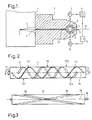
- An x-ray beam 3 extends from the focus 2 located in the housing 1 of an x-ray emitter and passes through the radiation window 4 of the x-ray emitter.
- a housing 5 is connected to the housing 1, which fades out a beam fan 31 of a few millimeters thick from the x-ray beam 3 in a plane perpendicular to the plane of the drawing in FIG. 1.
- the diaphragm arrangement 5 faces away from the X-ray emitter 1 End a cylindrical opening 6, in which a first hollow cylindrical diaphragm body 7 is arranged, which surrounds a second diaphragm body 8 arranged concentrically thereto.
- the common axis of symmetry and axis of rotation of the diaphragm body 7 and 8 is in the plane of the beam fan 31, in such a way that the connecting line of the focus 2 with the center of the diaphragm body intersects the axis of symmetry at right angles.
- the rotatably mounted diaphragm bodies 7 and 8 are driven by a drive arrangement in such a way that the first diaphragm body 7 rotates faster than the diaphragm body 8 by a factor of 6.
- the drive arrangement could for this purpose contain a single motor, which has appropriately designed translations with the diaphragm bodies 7 and 8 would be coupled.
- FIG. 1 - for the sake of simplicity - a drive device with two stepper motors 9 and 10 is shown, of which the stepper motor 9 coupled to the outer diaphragm body 7 is directly coupled to a stepper pulse generator 11, while the stepper motor acting on the second diaphragm body 8 10 is connected to it via a frequency divider 12 which reduces the step frequency in a ratio of 1: 6.
- the diaphragm body 7 rotates at six times the speed of the inner diaphragm body.
- a single x-ray beam 32 is faded out of the beam fan 31 by the diaphragm bodies 7 and 8, the dimensions of which in the vertical direction (perpendicular to the plane of the beam fan 31) are only 0.5 mm wide and perpendicular to the plane of the slot 13 are limited and its dimensions in the axial direction by the design of the Aperture body 7 can be determined.
- the diaphragm bodies rotate at a constant speed, the x-ray beam 32 changes its point of impact on a plane perpendicular to the plane of the drawing according to a sawtooth-shaped time function.
- the diaphragm body consists of a material of such a strength that the X-ray radiation emanating from the focus 2 is thereby practically completely absorbed, for example from a 1 mm thick tungsten alloy.
- the diaphragm body can have a length of, for example, 50 mm and a diameter of 12 mm.
- At least one of the hollow shafts 71 on its end faces is coupled to the drive device explained in more detail with reference to FIG. 1.
- two helical slits are provided which are offset with respect to one another and circulate in the same direction, each of which has a constant pitch. Both slots have three turns or coils.
- the slot 73 has a larger pitch (this is the ratio between the axial length of a turn and the circumference of the body 7) than the slot 72.
- the slot 73 has a width of 0.4 mm, while the slot 72 is considerably wider , for example 2 mm.
- the axial length of the slot 73 is slightly shorter than the length of the diaphragm body 7; if the slot were just as long, it would cut the panel body into two non-contiguous parts.
- n 1 or 2 or 4, 5, 6, etc.
- the first diaphragm body would have to be rotated by a factor of 2n faster than the second diaphragm body 8. If the coils in the diaphragm body 7 had the same rotation have sense as in the panel body 8, the panel body must be rotated in the same direction; if the direction of rotation is not the same, rotation with the opposite direction of rotation is required.
- the two slots are offset from one another in such a way that they are offset exactly around 1800 on the circumference in the center of the diaphragm body, indicated by arrow 70.
- an x-ray beam can therefore pass through the slits 72 and 73 in the center of the diaphragm body perpendicular to the plane of the drawing - if the focus of the radiation source is exactly in the middle behind the diaphragm body.
- the slot 72 on the side facing the focus intersects the plane which is formed by the focus and the axis of symmetry or axis of rotation 75.
- the axial position of these points is indicated by arrows 721 and 723.
- the three X-rays move to the left or to the right, depending on the direction of rotation, when the diaphragm body is rotated, until the first beam reaches one end of the slot, after which another beam emerges at the other end.
- the cross section of an X-ray beam 32 emerging from the diaphragm arrangement 5 is determined in the axial direction by the dimensions of the thinner slit and in the plane perpendicular to the fan beam 31 by the opening of the slit diaphragm 13 . It would also be possible to make the slot 72 as narrow as the slot 73, so that the slot diaphragm 13 could even be dispensed with. With finite dimensions of focus 2, however, this would increase the geometric blur of the x-ray beam and the arrangement would be more sensitive to production scatter in the position of focus 2 with respect to the diaphragm body. Therefore, the arrangement with a wider slot 72 with a smaller pitch and an additional slot diaphragm 13 is preferred.
- the diaphragm body 7 blocks (at least) as much X-rays as the slits Have turns.
- only one X-ray beam is desired. This could be achieved if slots with only a single turn were provided, but in this case the slots or their projection would intersect the plane of the fan beam at a much more acute angle, so that the axial dimensions are undesirably essential for the same slot width would be enlarged.
- a different route is therefore followed: only one of the X-rays that could penetrate the diaphragm body is passed through.
- the second diaphragm body 8 serves this purpose (FIG. 3).
- the second diaphragm body 8 is in turn a hollow cylinder which can be made of the same material as the first diaphragm body and which has a shaft coupled to the drive device 9 ... 12 (FIG. 1) on at least one end face.
- this diaphragm body corresponds to that according to EP-OS 74 021, i.e. it is provided with two slots 82 and 83 which are offset from one another on the circumference by 180 °, each of which extends over the same axial length and has the shape of a helix.
- the two slots 82 and 83 have only half a turn, i.e. they extend on the circumference of the panel body 8 over an arc of only 180 °.
- the slots 82 and 83 are much wider than the narrow slot 73 on the first panel body.
- the two diaphragm bodies are in a suitable position relative to one another, two of the three X-rays that could pass through the first diaphragm body are absorbed, for example the two outer ones, and only the middle one is transmitted.
- this X-ray beam moves in both diaphragm bodies at the same speed, so that only this one X-ray beam is always transmitted.
- the number a of the turns of the slots 72, 73 in the first diaphragm body 7, which the X-ray beam passes through in the course of its axial movement, does not necessarily have to be an integer, and the corresponding number b for the second diaphragm body 8 must not be exactly 0.5.
- this diaphragm body can have a semicircular cross-section and can be provided with only a single slot which extends over the length of the diaphragm body and describes an arc of at least approximately 180 °.
- a hollow cylindrical body with a semicircular cross section can be used, which is provided on its circumference with a plurality of openings offset in the axial and circumferential directions.
- the X-ray beam then jumps from one opening to the other.
- the advantage of the embodiment shown in Fig. 3 over the latter also consists in the fact that this diaphragm body has no imbalance.
Landscapes
- Physics & Mathematics (AREA)
- Spectroscopy & Molecular Physics (AREA)
- Engineering & Computer Science (AREA)
- General Engineering & Computer Science (AREA)
- High Energy & Nuclear Physics (AREA)
- Apparatus For Radiation Diagnosis (AREA)
- X-Ray Techniques (AREA)
Applications Claiming Priority (2)
| Application Number | Priority Date | Filing Date | Title |
|---|---|---|---|
| DE3908966A DE3908966A1 (de) | 1989-03-18 | 1989-03-18 | Anordnung zur erzeugung eines roentgen- oder gammastrahls mit geringem querschnitt und veraenderbarer lage |
| DE3908966 | 1989-03-18 |
Publications (3)
| Publication Number | Publication Date |
|---|---|
| EP0389033A2 true EP0389033A2 (fr) | 1990-09-26 |
| EP0389033A3 EP0389033A3 (fr) | 1991-07-31 |
| EP0389033B1 EP0389033B1 (fr) | 1994-10-26 |
Family
ID=6376681
Family Applications (1)
| Application Number | Title | Priority Date | Filing Date |
|---|---|---|---|
| EP90200571A Expired - Lifetime EP0389033B1 (fr) | 1989-03-18 | 1990-03-12 | Dispositif pour la génération d'une radiation X ou gamma à faible section et position variable |
Country Status (4)
| Country | Link |
|---|---|
| US (1) | US5038370A (fr) |
| EP (1) | EP0389033B1 (fr) |
| JP (1) | JP2940556B2 (fr) |
| DE (2) | DE3908966A1 (fr) |
Cited By (4)
| Publication number | Priority date | Publication date | Assignee | Title |
|---|---|---|---|---|
| WO1995028715A3 (fr) * | 1994-04-18 | 1995-11-30 | Bgc Dev Ab | Source mobile de rayons x avec ou sans collimateur |
| EP1772874A3 (fr) * | 2005-10-06 | 2007-08-22 | Bundesanstalt Für Materialforschung Und -Prufung (Bam) | Diaphragme orienté vers le foyer |
| EP2573551A4 (fr) * | 2010-12-31 | 2014-04-23 | Nuctech Co Ltd | Dispositif et procédé pour balayage de faisceau de rayonnement pour réalisation d'image de rétro-dispersion |
| CN105987920A (zh) * | 2015-02-11 | 2016-10-05 | 北京君和信达科技有限公司 | 一种飞点形成装置及设计方法 |
Families Citing this family (31)
| Publication number | Priority date | Publication date | Assignee | Title |
|---|---|---|---|---|
| US5212718A (en) * | 1991-08-06 | 1993-05-18 | The United States Of America As Represented By The Administrator Of The National Aeronautics And Space Administration | Gamma ray collimator |
| US5493596A (en) * | 1993-11-03 | 1996-02-20 | Annis; Martin | High-energy X-ray inspection system |
| US6192104B1 (en) | 1998-11-30 | 2001-02-20 | American Science And Engineering, Inc. | Fan and pencil beams from a common source for x-ray inspection |
| US6272206B1 (en) * | 1999-11-03 | 2001-08-07 | Perkinelmer Detection Systems, Inc. | Rotatable cylinder dual beam modulator |
| DE60222768T2 (de) * | 2001-04-03 | 2008-07-17 | Koninklijke Philips Electronics N.V. | Computertomograph |
| US7963695B2 (en) | 2002-07-23 | 2011-06-21 | Rapiscan Systems, Inc. | Rotatable boom cargo scanning system |
| RU2256905C2 (ru) * | 2003-03-24 | 2005-07-20 | Мирочник Эммануил Абрамович | Комплекс рентгенографической инспекции |
| US8995619B2 (en) | 2010-03-14 | 2015-03-31 | Rapiscan Systems, Inc. | Personnel screening system |
| US8576982B2 (en) | 2008-02-01 | 2013-11-05 | Rapiscan Systems, Inc. | Personnel screening system |
| US8638904B2 (en) | 2010-03-14 | 2014-01-28 | Rapiscan Systems, Inc. | Personnel screening system |
| US9310323B2 (en) | 2009-05-16 | 2016-04-12 | Rapiscan Systems, Inc. | Systems and methods for high-Z threat alarm resolution |
| ITTO20090946A1 (it) | 2009-12-01 | 2011-06-02 | Varian Spa | Metodo per migliorare l efficienza di scambio termico fra un corpo metallico ed un tubo in cui scorre un fluido di scambio termico. |
| CN103558240B (zh) | 2009-12-30 | 2016-03-09 | 同方威视技术股份有限公司 | 一种成像用射线束的扫描装置和方法 |
| WO2011115929A1 (fr) * | 2010-03-14 | 2011-09-22 | Rapiscan Systems, Inc. | Systèmes de détection multi-écrans |
| US8908831B2 (en) | 2011-02-08 | 2014-12-09 | Rapiscan Systems, Inc. | Covert surveillance using multi-modality sensing |
| CA3078117A1 (fr) | 2011-06-14 | 2012-12-20 | Rapiscan Systems, Inc. | Surveillance furtive par detection multimodale |
| MX340645B (es) * | 2012-07-05 | 2016-07-18 | American Science & Eng Inc | Colimador de angulo variable. |
| US9557427B2 (en) | 2014-01-08 | 2017-01-31 | Rapiscan Systems, Inc. | Thin gap chamber neutron detectors |
| GB2538921B (en) | 2014-03-07 | 2020-06-03 | Rapiscan Systems Inc | Ultra wide band detectors |
| US11280898B2 (en) | 2014-03-07 | 2022-03-22 | Rapiscan Systems, Inc. | Radar-based baggage and parcel inspection systems |
| EP3944260B1 (fr) * | 2014-05-22 | 2024-05-08 | Australian Nuclear Science And Technology Organisation | Imagerie par protons, neutrons, electrons ou rayonnement electromagnetique |
| AU2015353439A1 (en) | 2014-11-25 | 2017-06-29 | Rapiscan Systems, Inc. | Intelligent security management system |
| US10535491B2 (en) | 2015-01-20 | 2020-01-14 | American Science And Engineering, Inc. | Dynamically adjustable focal spot |
| US10082473B2 (en) | 2015-07-07 | 2018-09-25 | General Electric Company | X-ray filtration |
| HK1257878A1 (zh) | 2015-09-10 | 2019-11-01 | American Science And Engineering, Inc. | 使用行间自适应电磁x射线扫描的反向散射表徵 |
| CN109791811A (zh) | 2016-09-30 | 2019-05-21 | 美国科学及工程股份有限公司 | 用于2d扫描光束成像的x射线源 |
| US10748740B2 (en) * | 2018-08-21 | 2020-08-18 | Fei Company | X-ray and particle shield for improved vacuum conductivity |
| US10948614B2 (en) * | 2018-11-01 | 2021-03-16 | H3D, Inc. | Imaging system with one or more mask units and corresponding method of recording radiation |
| US11193898B1 (en) | 2020-06-01 | 2021-12-07 | American Science And Engineering, Inc. | Systems and methods for controlling image contrast in an X-ray system |
| US12259341B2 (en) | 2021-11-04 | 2025-03-25 | Rapiscan Holdings, Inc. | Targeted collimation of detectors using rear collimators |
| US11972920B2 (en) | 2021-11-23 | 2024-04-30 | Fei Company | Vacuum compatible X-ray shield |
Family Cites Families (9)
| Publication number | Priority date | Publication date | Assignee | Title |
|---|---|---|---|---|
| DE194743C (fr) * | ||||
| US3766387A (en) * | 1972-07-11 | 1973-10-16 | Us Navy | Nondestructive test device using radiation to detect flaws in materials |
| US3832564A (en) * | 1973-01-31 | 1974-08-27 | Us Navy | Radiation absorber and intensity collimator unit |
| US3894234A (en) * | 1974-01-28 | 1975-07-08 | Us Navy | Radial scanner |
| DE3120567A1 (de) * | 1981-05-23 | 1983-01-20 | Philips Patentverwaltung Gmbh, 2000 Hamburg | Streustrahlen-untersuchungsanordnung |
| DE3135421A1 (de) * | 1981-09-07 | 1983-03-24 | Siemens AG, 1000 Berlin und 8000 München | Roentgenuntersuchungsgeraet |
| DE3443095A1 (de) * | 1984-11-27 | 1986-05-28 | Philips Patentverwaltung Gmbh, 2000 Hamburg | Anordnung zur untersuchung eines koerpers mit gamma- oder roentgenstrahlung |
| GB2170980B (en) * | 1985-02-07 | 1988-05-25 | Steve Webb | Ct scanner and detector therefor |
| DE3829688A1 (de) * | 1988-09-01 | 1990-03-15 | Philips Patentverwaltung | Anordnung zur erzeugung eines roentgen- oder gammastrahls mit geringem querschnitt und veraenderlicher richtung |
-
1989
- 1989-03-18 DE DE3908966A patent/DE3908966A1/de not_active Withdrawn
-
1990
- 1990-03-12 EP EP90200571A patent/EP0389033B1/fr not_active Expired - Lifetime
- 1990-03-12 DE DE59007543T patent/DE59007543D1/de not_active Expired - Fee Related
- 1990-03-14 US US07/494,041 patent/US5038370A/en not_active Expired - Lifetime
- 1990-03-15 JP JP2065527A patent/JP2940556B2/ja not_active Expired - Lifetime
Cited By (6)
| Publication number | Priority date | Publication date | Assignee | Title |
|---|---|---|---|---|
| WO1995028715A3 (fr) * | 1994-04-18 | 1995-11-30 | Bgc Dev Ab | Source mobile de rayons x avec ou sans collimateur |
| EP1772874A3 (fr) * | 2005-10-06 | 2007-08-22 | Bundesanstalt Für Materialforschung Und -Prufung (Bam) | Diaphragme orienté vers le foyer |
| EP2573551A4 (fr) * | 2010-12-31 | 2014-04-23 | Nuctech Co Ltd | Dispositif et procédé pour balayage de faisceau de rayonnement pour réalisation d'image de rétro-dispersion |
| US8983033B2 (en) | 2010-12-31 | 2015-03-17 | Nuctech Company Limited | Scanning device and method for back-scatter imaging with a radiation beam |
| CN105987920A (zh) * | 2015-02-11 | 2016-10-05 | 北京君和信达科技有限公司 | 一种飞点形成装置及设计方法 |
| CN105987920B (zh) * | 2015-02-11 | 2019-10-08 | 北京君和信达科技有限公司 | 一种飞点形成装置及设计方法 |
Also Published As
| Publication number | Publication date |
|---|---|
| EP0389033B1 (fr) | 1994-10-26 |
| DE3908966A1 (de) | 1990-09-20 |
| DE59007543D1 (de) | 1994-12-01 |
| US5038370A (en) | 1991-08-06 |
| JPH02275400A (ja) | 1990-11-09 |
| EP0389033A3 (fr) | 1991-07-31 |
| JP2940556B2 (ja) | 1999-08-25 |
Similar Documents
| Publication | Publication Date | Title |
|---|---|---|
| EP0389033B1 (fr) | Dispositif pour la génération d'une radiation X ou gamma à faible section et position variable | |
| EP0357146A2 (fr) | Dispositif pour générer un faisceau de rayons X ou gamma de petite section transversale et de direction variable | |
| DE3126285C2 (fr) | ||
| DE2744808C2 (de) | Röntgenstrahler mit einer Röntgenröhre mit Drehanode und einer eine Fokussierungselektrode zum Ausblenden eines rechteckigen Brennflecks aufweisenden Kathodenanordnung | |
| DE4122273C2 (de) | Vorrichtung zum transversalen Schneiden eines sich fortbewegenden Streifens | |
| CH623090A5 (fr) | ||
| EP0989520A2 (fr) | Procédé de tomographie par calculateur avec faisceau en forme conique | |
| DE2621565C3 (de) | Schrittgetriebe | |
| DE68908231T2 (de) | Röntgenuntersuchungsapparat mit einstellbarer schlitzförmiger Blende. | |
| DE3827511A1 (de) | Roentgenstrahlquelle mit selektiver erzeugung punktfokussierter und linienfokussierter roentgenstrahlen | |
| DE1589825B2 (de) | Elektronenoptisches System zum Fokussieren und Ablenken eines Elektronenstrahls | |
| DE2631516A1 (de) | Roentgenroehre | |
| DE102006007058A1 (de) | CT-System mit mindestens zwei Fokus/Detektor-Systemen | |
| DE19956585A1 (de) | Computertomographie-Verfahren | |
| EP0593961A1 (fr) | Séparateur de faisceaux optique spécialement pour un faisceau laser | |
| DE19831027A1 (de) | Effektscheibenrotationssystem | |
| EP1000408B1 (fr) | Procede de tomographie avec balayage helicoidal d'une zone d'examen | |
| DE10154539C1 (de) | Strahlenblende für ein Röntgengerät und Röntgengerät | |
| DE1961648C3 (de) | Goniometrische Einrichtung für Beugungsuntersuchungen | |
| DE2533347C3 (de) | Magnetischer Reflektor | |
| DE3434369A1 (de) | Tomographisches panorama-roentgengeraet | |
| DE2913769C2 (fr) | ||
| DE2722276A1 (de) | Abstimmbares magnetron | |
| DE102020202585A1 (de) | Röntgenquellenvorrichtung umfassend eine Anode zur Erzeugung von Röntgenstrahlen | |
| DE2440810C3 (de) | Verfahren zum Betrieb eines Mischers |
Legal Events
| Date | Code | Title | Description |
|---|---|---|---|
| PUAI | Public reference made under article 153(3) epc to a published international application that has entered the european phase |
Free format text: ORIGINAL CODE: 0009012 |
|
| AK | Designated contracting states |
Kind code of ref document: A2 Designated state(s): DE FR GB IT SE |
|
| PUAL | Search report despatched |
Free format text: ORIGINAL CODE: 0009013 |
|
| AK | Designated contracting states |
Kind code of ref document: A3 Designated state(s): DE FR GB IT SE |
|
| 17P | Request for examination filed |
Effective date: 19920131 |
|
| 17Q | First examination report despatched |
Effective date: 19931214 |
|
| GRAA | (expected) grant |
Free format text: ORIGINAL CODE: 0009210 |
|
| AK | Designated contracting states |
Kind code of ref document: B1 Designated state(s): DE FR GB IT SE |
|
| PG25 | Lapsed in a contracting state [announced via postgrant information from national office to epo] |
Ref country code: IT Free format text: LAPSE BECAUSE OF FAILURE TO SUBMIT A TRANSLATION OF THE DESCRIPTION OR TO PAY THE FEE WITHIN THE PRE;WARNING: LAPSES OF ITALIAN PATENTS WITH EFFECTIVE DATE BEFORE 2007 MAY HAVE OCCURRED AT ANY TIME BEFORE 2007. THE CORRECT EFFECTIVE DATE MAY BE DIFFERENT FROM THE ONE RECORDED.SCRIBED TIME-LIMIT Effective date: 19941026 |
|
| REF | Corresponds to: |
Ref document number: 59007543 Country of ref document: DE Date of ref document: 19941201 |
|
| PG25 | Lapsed in a contracting state [announced via postgrant information from national office to epo] |
Ref country code: SE Effective date: 19950126 |
|
| GBT | Gb: translation of ep patent filed (gb section 77(6)(a)/1977) |
Effective date: 19950106 |
|
| ET | Fr: translation filed | ||
| REG | Reference to a national code |
Ref country code: FR Ref legal event code: CD |
|
| PLBE | No opposition filed within time limit |
Free format text: ORIGINAL CODE: 0009261 |
|
| STAA | Information on the status of an ep patent application or granted ep patent |
Free format text: STATUS: NO OPPOSITION FILED WITHIN TIME LIMIT |
|
| 26N | No opposition filed | ||
| REG | Reference to a national code |
Ref country code: FR Ref legal event code: CD |
|
| PGFP | Annual fee paid to national office [announced via postgrant information from national office to epo] |
Ref country code: DE Payment date: 19990205 Year of fee payment: 10 |
|
| PGFP | Annual fee paid to national office [announced via postgrant information from national office to epo] |
Ref country code: GB Payment date: 19990208 Year of fee payment: 10 |
|
| PGFP | Annual fee paid to national office [announced via postgrant information from national office to epo] |
Ref country code: FR Payment date: 19990215 Year of fee payment: 10 |
|
| REG | Reference to a national code |
Ref country code: GB Ref legal event code: 732E |
|
| REG | Reference to a national code |
Ref country code: FR Ref legal event code: TP |
|
| PG25 | Lapsed in a contracting state [announced via postgrant information from national office to epo] |
Ref country code: GB Free format text: LAPSE BECAUSE OF NON-PAYMENT OF DUE FEES Effective date: 20000312 |
|
| GBPC | Gb: european patent ceased through non-payment of renewal fee |
Effective date: 20000312 |
|
| PG25 | Lapsed in a contracting state [announced via postgrant information from national office to epo] |
Ref country code: FR Free format text: LAPSE BECAUSE OF NON-PAYMENT OF DUE FEES Effective date: 20001130 |
|
| REG | Reference to a national code |
Ref country code: FR Ref legal event code: ST |
|
| PG25 | Lapsed in a contracting state [announced via postgrant information from national office to epo] |
Ref country code: DE Free format text: LAPSE BECAUSE OF NON-PAYMENT OF DUE FEES Effective date: 20010103 |