EP0389436A2 - Cadre portant - Google Patents
Cadre portant Download PDFInfo
- Publication number
- EP0389436A2 EP0389436A2 EP90810211A EP90810211A EP0389436A2 EP 0389436 A2 EP0389436 A2 EP 0389436A2 EP 90810211 A EP90810211 A EP 90810211A EP 90810211 A EP90810211 A EP 90810211A EP 0389436 A2 EP0389436 A2 EP 0389436A2
- Authority
- EP
- European Patent Office
- Prior art keywords
- connection
- connection housing
- housing
- slots
- tubular column
- Prior art date
- Legal status (The legal status is an assumption and is not a legal conclusion. Google has not performed a legal analysis and makes no representation as to the accuracy of the status listed.)
- Withdrawn
Links
Images

Classifications
-
- F—MECHANICAL ENGINEERING; LIGHTING; HEATING; WEAPONS; BLASTING
- F16—ENGINEERING ELEMENTS AND UNITS; GENERAL MEASURES FOR PRODUCING AND MAINTAINING EFFECTIVE FUNCTIONING OF MACHINES OR INSTALLATIONS; THERMAL INSULATION IN GENERAL
- F16M—FRAMES, CASINGS OR BEDS OF ENGINES, MACHINES OR APPARATUS, NOT SPECIFIC TO ENGINES, MACHINES OR APPARATUS PROVIDED FOR ELSEWHERE; STANDS; SUPPORTS
- F16M11/00—Stands or trestles as supports for apparatus or articles placed thereon ; Stands for scientific apparatus such as gravitational force meters
- F16M11/20—Undercarriages with or without wheels
- F16M11/24—Undercarriages with or without wheels changeable in height or length of legs, also for transport only, e.g. by means of tubes screwed into each other
-
- A—HUMAN NECESSITIES
- A47—FURNITURE; DOMESTIC ARTICLES OR APPLIANCES; COFFEE MILLS; SPICE MILLS; SUCTION CLEANERS IN GENERAL
- A47B—TABLES; DESKS; OFFICE FURNITURE; CABINETS; DRAWERS; GENERAL DETAILS OF FURNITURE
- A47B57/00—Cabinets, racks or shelf units, characterised by features for adjusting shelves or partitions
- A47B57/30—Cabinets, racks or shelf units, characterised by features for adjusting shelves or partitions with means for adjusting the height of detachable shelf supports
- A47B57/36—Cabinets, racks or shelf units, characterised by features for adjusting shelves or partitions with means for adjusting the height of detachable shelf supports consisting of side walls of the ladder type
-
- F—MECHANICAL ENGINEERING; LIGHTING; HEATING; WEAPONS; BLASTING
- F16—ENGINEERING ELEMENTS AND UNITS; GENERAL MEASURES FOR PRODUCING AND MAINTAINING EFFECTIVE FUNCTIONING OF MACHINES OR INSTALLATIONS; THERMAL INSULATION IN GENERAL
- F16M—FRAMES, CASINGS OR BEDS OF ENGINES, MACHINES OR APPARATUS, NOT SPECIFIC TO ENGINES, MACHINES OR APPARATUS PROVIDED FOR ELSEWHERE; STANDS; SUPPORTS
- F16M11/00—Stands or trestles as supports for apparatus or articles placed thereon ; Stands for scientific apparatus such as gravitational force meters
- F16M11/20—Undercarriages with or without wheels
- F16M11/22—Undercarriages with or without wheels with approximately constant height, e.g. with constant length of column or of legs
-
- Y—GENERAL TAGGING OF NEW TECHNOLOGICAL DEVELOPMENTS; GENERAL TAGGING OF CROSS-SECTIONAL TECHNOLOGIES SPANNING OVER SEVERAL SECTIONS OF THE IPC; TECHNICAL SUBJECTS COVERED BY FORMER USPC CROSS-REFERENCE ART COLLECTIONS [XRACs] AND DIGESTS
- Y10—TECHNICAL SUBJECTS COVERED BY FORMER USPC
- Y10T—TECHNICAL SUBJECTS COVERED BY FORMER US CLASSIFICATION
- Y10T403/00—Joints and connections
- Y10T403/46—Rod end to transverse side of member
- Y10T403/4602—Corner joint
-
- Y—GENERAL TAGGING OF NEW TECHNOLOGICAL DEVELOPMENTS; GENERAL TAGGING OF CROSS-SECTIONAL TECHNOLOGIES SPANNING OVER SEVERAL SECTIONS OF THE IPC; TECHNICAL SUBJECTS COVERED BY FORMER USPC CROSS-REFERENCE ART COLLECTIONS [XRACs] AND DIGESTS
- Y10—TECHNICAL SUBJECTS COVERED BY FORMER USPC
- Y10T—TECHNICAL SUBJECTS COVERED BY FORMER US CLASSIFICATION
- Y10T403/00—Joints and connections
- Y10T403/70—Interfitted members
- Y10T403/7045—Interdigitated ends
Definitions
- the present invention relates to a support frame according to the preamble of claim 1.
- Supporting frames of this type are much more difficult to realize if the crossbeams have to be arranged closely next to each other for reasons of design and also close to the foot, because even with a precise engagement fit hardly any shake-proof connections can be made.
- the object of the present invention is therefore to provide a support frame according to the modular principle, in which cross members in multiple bar element arrangements can be stably installed close to one another by means of conventional hook engagement means on pairs of columns.
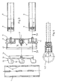
- Fig. 1 shows two tubular columns 1 and 2, which are designed to be independent of each other by schematically indicated foot arrangements 1.1, 2.1 and which are provided in a known manner with suspension slots 3 which are parallel to the longitudinal axis and are equipped with arms or support arrangements for the presentation of goods.
- suspension slots 3 which are parallel to the longitudinal axis and are equipped with arms or support arrangements for the presentation of goods.
- these are non-positively connected to one another by means of a cross connection 4 arranged in the lower column area, preferably in the foot area thereof.
- the advantage of such a connection arrangement is that most of the column length for the arrangement of goods support elements on a stable, system parts based on the modular principle is available.
- Fig. 2 shows a larger scale on the left a connection device in section.
- Two connecting tubes 5, 6 running parallel in vertical distance are firmly anchored in a connection housing 8 by means of screws 7.
- the connecting tubes 5, 6 contain anchoring plates 9 with a central threaded bore 10.
- the tube ends are seated in fitting recesses 11 in the connection housing 8 and are detachably connected to the latter by the screws 7 according to FIG. 2.
- This type of pipe attachment allows the user of the support frame according to the invention to use connecting tubes 5, 6 of the appropriate length in each case when building a frame.
- connection housing 8 has a breast-side receiving opening 12 in which a tensioning bracket 13, consisting of a base plate 14 and a latching web 15 welded thereon with, for example, three latching lugs 16, is mounted.
- a tensioning bracket 13 is initially held loosely in its receiving opening 12 by a tensioning screw 17, which is mounted in a housing web 18.
- the tensioning screw 17 is tightened.
- the latching lugs 16 lie on the inside and the chest surface 19 (FIG. 4) of the connection housing 8 on the outside in a form-fitting and non-positive manner against the relevant support column 1, 2.
- connection housing 8 In order to prevent the cross-connection 4 from being lifted off the associated tubular column 1, 2 in the event of an undesired or accidental slight loosening of the tensioning screw 17, the connection housing 8 (FIGS. 3, 4) has a radially inward projection on the top of the breast surface 19 Locking cam 21. This engages under the inserted into the associated slots 3 locking cams 16 the upper narrow side wall of the slot 3 occupied by the uppermost locking lug 16 and, in its function as a stop element, prevents the cross connection 4 from being lifted off the related column 1, 2. A lifting of the cross-connection 4 from one of the columns 1, 2 can therefore only take place when the connection housing 8 can be pulled away from the column by an amount corresponding to the column wall thickness.
- connection housing 8 has a surface contour that is complementary to the outer contour of the support column 1, 2.
- the head of the clamping screw 17 always remains accessible for handling the cross-connection 4 and can be hidden by an inverted U-shaped cover 20 (FIGS. 1, 2) covering the connecting tubes 5, 6.
- the cross-connection 4 can also be designed with three or more connecting tubes 5, 6 while expanding the connection housing 8.
- the number of latching lugs 16 on the clamping brackets 13 is not limited to three. Tensioning brackets with two or four latching lugs 16 can also be used.
Landscapes
- Engineering & Computer Science (AREA)
- General Engineering & Computer Science (AREA)
- Mechanical Engineering (AREA)
- Mutual Connection Of Rods And Tubes (AREA)
Applications Claiming Priority (2)
| Application Number | Priority Date | Filing Date | Title |
|---|---|---|---|
| CH1033/89A CH678144A5 (fr) | 1989-03-21 | 1989-03-21 | |
| CH1033/89 | 1989-03-21 |
Publications (2)
| Publication Number | Publication Date |
|---|---|
| EP0389436A2 true EP0389436A2 (fr) | 1990-09-26 |
| EP0389436A3 EP0389436A3 (fr) | 1992-01-08 |
Family
ID=4200881
Family Applications (1)
| Application Number | Title | Priority Date | Filing Date |
|---|---|---|---|
| EP19900810211 Withdrawn EP0389436A3 (fr) | 1989-03-21 | 1990-03-19 | Cadre portant |
Country Status (4)
| Country | Link |
|---|---|
| US (1) | US5026014A (fr) |
| EP (1) | EP0389436A3 (fr) |
| CH (1) | CH678144A5 (fr) |
| DE (1) | DE9002965U1 (fr) |
Cited By (1)
| Publication number | Priority date | Publication date | Assignee | Title |
|---|---|---|---|---|
| FR2676904A1 (fr) * | 1991-05-31 | 1992-12-04 | Rubbermaid Office Prod | Appareil de support d'accessoires personnels detachable utilisable avec des dispositifs de panneaux. |
Family Cites Families (8)
| Publication number | Priority date | Publication date | Assignee | Title |
|---|---|---|---|---|
| US3273720A (en) * | 1966-09-20 | Storage racks | ||
| DE1971223U (de) * | 1967-06-06 | 1967-10-26 | Heinrich Dustmann | Versteifungselement fuer veraenderbare regale od. dgl. |
| US3507228A (en) * | 1968-01-22 | 1970-04-21 | Hirsh Mfg Co Sa | Shelf end-stop for steel shelving |
| US4064996A (en) * | 1975-12-17 | 1977-12-27 | Robert L. Shillum | Rack system |
| ZA822552B (en) * | 1981-04-22 | 1983-03-30 | Dexion Comino Int Ltd | Framework connection means |
| US4406374A (en) * | 1981-08-12 | 1983-09-27 | Myco, Inc. | Locking device for display rack |
| US4540308A (en) * | 1983-12-27 | 1985-09-10 | Edward Colby | Joint for furniture support structure |
| US4874148A (en) * | 1986-12-12 | 1989-10-17 | Newell Co. | Universal display bracket |
-
1989
- 1989-03-21 CH CH1033/89A patent/CH678144A5/de not_active IP Right Cessation
-
1990
- 1990-03-15 DE DE9002965U patent/DE9002965U1/de not_active Expired - Lifetime
- 1990-03-16 US US07/494,574 patent/US5026014A/en not_active Expired - Fee Related
- 1990-03-19 EP EP19900810211 patent/EP0389436A3/fr not_active Withdrawn
Cited By (1)
| Publication number | Priority date | Publication date | Assignee | Title |
|---|---|---|---|---|
| FR2676904A1 (fr) * | 1991-05-31 | 1992-12-04 | Rubbermaid Office Prod | Appareil de support d'accessoires personnels detachable utilisable avec des dispositifs de panneaux. |
Also Published As
| Publication number | Publication date |
|---|---|
| CH678144A5 (fr) | 1991-08-15 |
| EP0389436A3 (fr) | 1992-01-08 |
| DE9002965U1 (de) | 1990-05-17 |
| US5026014A (en) | 1991-06-25 |
Similar Documents
| Publication | Publication Date | Title |
|---|---|---|
| DE60212812T2 (de) | Vertikal stabilisierte regalbügelgruppe | |
| WO1999020094A2 (fr) | Systemes de barres de support pour etablissements de commerce et de service | |
| DE3925302C2 (fr) | ||
| EP1631172A1 (fr) | Dispositif pour maintenir une barre transversale qui prend appui sur des bras porteurs | |
| EP0389436A2 (fr) | Cadre portant | |
| DE19650000C2 (de) | Anordnung zur Anbringung von Hilfsgeräten oder Hilfsarmaturen in einem Dusch- oder Wannenraum | |
| DE202013006958U1 (de) | Vorrichtung zur Warenpräsentation | |
| DE3119207A1 (de) | "vorrichtung zur praesentation und lagerung von waren unterschiedlicher art auf warenboeden | |
| DE20003623U1 (de) | Hängeanordnung zum Halten von Toilettenartikeln | |
| DE29705604U1 (de) | Regalsystem | |
| DE4114378C2 (fr) | ||
| DE19931040C2 (de) | Verkleidungssystem für eine Wanne, vorzugsweise Badewanne | |
| DE19956951C2 (de) | Arbeitsplatzmöbel mit einem Möbelgestell aus vertikalen Säulen und Quertraversen | |
| AT207524B (de) | Einrichtungsgestell, insbesondere für Geschäftslokale | |
| WO2019029773A1 (fr) | Crochet mural | |
| CH652580A5 (de) | Kleider- oder warenpraesentiergestell. | |
| DE102005020253B4 (de) | Regalsystem | |
| EP1061837A2 (fr) | Systemes de barres de support pour etablissements de commerce et de service | |
| DE4034909C2 (de) | Schnell montierbares und demontierbares Halterungssystem | |
| DE29603221U1 (de) | Ständerplatte zur Warenpräsentation | |
| AT406437B (de) | Vorrichtung zur befestigung der frontblende einer schublade | |
| DE29712525U1 (de) | Tragvorrichtung, insbesondere für Regale o.dgl. | |
| EP1075809A1 (fr) | Montant pour rayonnage | |
| EP0548786A1 (fr) | Portemanteaux | |
| DE20022725U1 (de) | Wandprofilleiste |
Legal Events
| Date | Code | Title | Description |
|---|---|---|---|
| PUAI | Public reference made under article 153(3) epc to a published international application that has entered the european phase |
Free format text: ORIGINAL CODE: 0009012 |
|
| AK | Designated contracting states |
Kind code of ref document: A2 Designated state(s): AT BE DE FR GB IT NL |
|
| PUAL | Search report despatched |
Free format text: ORIGINAL CODE: 0009013 |
|
| AK | Designated contracting states |
Kind code of ref document: A3 Designated state(s): AT BE DE FR GB IT NL |
|
| 17P | Request for examination filed |
Effective date: 19920131 |
|
| 17Q | First examination report despatched |
Effective date: 19930628 |
|
| STAA | Information on the status of an ep patent application or granted ep patent |
Free format text: STATUS: THE APPLICATION IS DEEMED TO BE WITHDRAWN |
|
| 18D | Application deemed to be withdrawn |
Effective date: 19931224 |