EP0389458A2 - Presse à pinçage prolongé - Google Patents
Presse à pinçage prolongé Download PDFInfo
- Publication number
- EP0389458A2 EP0389458A2 EP90850100A EP90850100A EP0389458A2 EP 0389458 A2 EP0389458 A2 EP 0389458A2 EP 90850100 A EP90850100 A EP 90850100A EP 90850100 A EP90850100 A EP 90850100A EP 0389458 A2 EP0389458 A2 EP 0389458A2
- Authority
- EP
- European Patent Office
- Prior art keywords
- glide
- belt
- press
- roll
- extended
- Prior art date
- Legal status (The legal status is an assumption and is not a legal conclusion. Google has not performed a legal analysis and makes no representation as to the accuracy of the status listed.)
- Granted
Links
Images


Classifications
-
- D—TEXTILES; PAPER
- D21—PAPER-MAKING; PRODUCTION OF CELLULOSE
- D21F—PAPER-MAKING MACHINES; METHODS OF PRODUCING PAPER THEREON
- D21F3/00—Press section of machines for making continuous webs of paper
- D21F3/02—Wet presses
- D21F3/0209—Wet presses with extended press nip
- D21F3/0218—Shoe presses
- D21F3/0227—Belts or sleeves therefor
- D21F3/0245—Means for fixing the sleeve to the roller end
Definitions
- the invention concerns an extended-nip press for dewatering of a paper or board web, comprising a counter-member, most appropriately a press roll, which forms an extended press zone together with a press-glide shoe and a glide belt running around the shoe, through which said zone at least one dewatering fabric and the web from which water is removed and which is supported by said fabric are passed, and which said glide belt is passed over a leading and tensioning member.
- extended-nip presses wherein the press zone is formed between a revolving belt mantle provided with a stationary core and a counter-roll.
- stationary roll core hydraulically or hydrodynamically loaded pressure shoes are used, by whose means, by the intermediate of the revolving mantle, a compression pressure is applied to the web towards the counter-roll.
- the counter-roll may be either an ordinary smooth-faced or hollow-faced press roll, a variable-crown roll, or a belt mantle provided with a hydraulic glide shoe.
- the press forces employed in extended-nip presses are of an order of 107 N, in which case a fully carrying lubricant film must be provided between the glide shoe and the belt mantle.
- water is not adequate as a lubricant, but it is necessary to use different lubrication oils and hydrodynamic or hydrostatic lubrication chambers, the pressure level employed in said chambers being of an order of 4...8 MPa.
- the thickness of the belt mantles used is about 3...6 mm. This is why they can be guided exclusively by drawing, which also causes its problems in the guiding of the belts.
- one object of the present invention is to make the intervals between said standstills longer.
- An object of the present invention is to combine the good properties of a belt-mantle construction closed at its ends and of an open belt.
- An object of the invention is to provide such an extended-nip press belonging to the species concerned wherein the opening gap of the nip can be made sufficiently large, as a rule about 30...50 mm, so that the glide belt and the press felts can be replaced as quickly as possible.
- the main object of the present invention is to provide an extended-nip press belonging to the species defined at the beginning which is also suitable for thin paper qualities and for high machine speeds.
- the mantle has to bend to a "concave” shape in the area subjected to nip load as well as to a "convex" shape in the end area constituting an extension of the nip. Moreover, the circumferential dimension of the belt mantle is little, and the frequency of load alternation becomes high.
- the object of the present invention is to avoid the drawbacks that have come out above and to provide an extended-nip press construction wherein a closed construction is combined with a good loading situation of the press belt also when a relatively long glide belt is used.
- the invention is mainly characterized in that the closed loop of said glide belt is guided around its leading and tensioning member so that, between said leading and tensioning member and the glide shoe and its possible guide parts, if any, the glide belt has substantially straight runs most appropriately parallel to one another, and that the space enclosed by said glide belt and susceptible of oil splashes is closed at both of the end areas of the loop of the glide belt by means of wall constructions.
- expansion joints arranged in such a way that movements of the glide shoe and the glide-belt leading and tensioning member in relation to one another are possible. Said expansion joints are, however, not always necessary if the resilience of the sealing members is suffi strictlyciently high in view of opening of the nip and even in view of tensioning of the belt.
- the press shoe which may be hydrodynamic or hydrostatic or a combination thereof, also forms the counter-face of one end area of the cycle of running of the glide belt, whereas the other end area consists of a roll or of a corresponding glide-shoe arrangement, which, at the same time, acts as a tensioning member.
- the latter roll or equivalent is preferably grooved.
- the aligning of the glide belt takes place by means of an alignment roll against a belt-guide roll or by means of an alignment roll against a support plate placed inside the belt loop.
- the alignment roll may consist of narrow resilient-faced "wheels”.
- prevention of leakage of the lubrication oil placed inside the belt loop takes place, e.g., by means of hose-loaded lubricated seal ribs, which are placed preferably at both sides of the glide belt.
- the diameter of the glide-belt guide roll or equivalent is equal to the belt-running width on the press shoe, tensioning and guiding of the belt do not cause problems of sealing at the ends.
- a length-variation joint of the seal ribs and a length-variation joint of the end plates of the belt loop are used. These joints can be arranged favourably without problems.
- the extended-nip press in accordance with the invention for thin paper is preferably a single-felt press, whereby the opposite roll is a smooth roll that transfers the paper web, and the hollow face may consist most appropriately of grooves, blind-drilled bores, or equivalent in the glide belt.
- the press for thin paper is most appropriately a single-felt press, the pressing result can be intensified by heating the press roll, e.g., by means of induction heating or IR-heating.
- the paper web and/or the press felt may also be heated by means known in prior art, such as by means of a steam box, an IR-heater, or a high-frequency heater.
- the extended-nip press in accordance with the invention is also advantageous with thin paper qualities when the pressure level is sufficient, i.e. about 7 MPa, which can be achieved. Further advantages include more efficient dewatering, whereby the number of nips can be lowered, low level of oscillations, and possibilities of improving the properties of quality of the paper.
- the invention will be described with reference to such an exemplifying embodiment only wherein the glide-belt/press-shoe device forms an extended nip with a counter-roll, it should be emphasized that the scope of the invention also includes extended-nip presses in which the counter-member consists of a member other than a press roll, e.g. a press-shoe device or a second glide-belt/press-shoe device or equivalent.
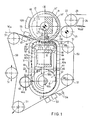
- the extended-nip press shown in Fig. 1 and having a wide press zone S comprises an upper counter-roll 10, which is provided with a mantle 11 revolving around a stationary central axle 12 on bearings 18a and 18b, said mantle 11 having a smooth outer face 11′ and a smooth inner face 11 ⁇ .
- the counter-roll 10 is a variable-crown roll provided with a journalling that withstands high loads and that consists of loading shoes 13 provided with loading members 14 and of liquid chambers 13a.
- a tubular roll journalled at its ends is also possible as a counter-roll 10.
- the counter-roll 10 is attached to its bearing supports 17a and 17b by its axle journals 15a and 15b, said bearing supports being provided with spherical bearings 16a and 16b.
- Figs. 1 and 2 show an extended-nip construction provided with one press felt 50, wherein the counter-roll 10 is a smooth-faced 11′, preferably metal-faced roll, which permits heating of the roll face, e.g., by means of induction heating devices 10A. It is also possible to use infra-heating devices or flame heaters. Heating that takes place from inside the roll 10 is also possible, when a variable-crown roll is used, e.g., by means of hot-oil heating and, when a tubular roll is used, by means of steam, induction heater, IR-heaters, or equivalent. Also, it is possible to employ simultaneous heating of the counter-roll 10 from inside and from outside as well as various combinations of the different modes of heating described above.
- the extended-nip press comprises a glide belt 40, which forms a closed belt mantle and which is preferably provided with an outside hollow face 40a in the construction which is shown in Figs. 1 and 2 and which uses one press felt 50.
- the hollow face 40a of the belt 40 is placed at the side of the press felt 50.
- the hollow face 40a in the belt 40 has been produced by means of grooves, blind-drilled bores, by means of a coarse wire-like fabric placed on the outer face of the belt 40, or as a combination thereof.
- the outer face of the belt 40 may also be smooth, but than requires intensified dewatering of the press felt 50, e.g.
- the glide belt 40 is preferably a polyurethane belt provided with a polyamide frame fabric. Moreover, the belt 40 may be made of a number of different composite materials.
- a transverse beam 30 is fitted, which is provided with closed ends 30a and 30b.
- Loading cylinders 31 are supported on the top side of the beam 30, and by means of the piston rods 32 of said loading cylinders forces are applied to the glide shoe 33 by whose means the compression pressure dewatering the web W is produced in the press zone S formed together with the counter-roll 10.
- the glide belt 40 has a tensioning roll 43, which is supported on the bearing supports 41a and 41b by its axle journals 43a and 43b by means of bearings 56a and 56b.
- the bearing supports 41a and 41b are supported on the bottom side of the beam 30 by means of power units 57a,58a and 57b,58b so that, by means of said power units, the belt 40 can be tensioned while the sealing of both of its ends 42a and 42b remains good.
- the belt 40 tensioning roll 34 is most appropriately provided with grooves 43c.
- the tensioning roll 43 may also be provided with an auxiliary drive, in which case it can be driven by means of the axle journal 43d.
- the bearing housings 41a and 41b which move during the tensioning, are sealed against the end plates 42a and 42b.
- the beam 30 is passed through the end plate 42a and 42b at both of its ends and, to prevent leakages of lubricant, the beam is also sealed against the end plates 42a and 42b.
- joints 61 which permit movements of the tensioning roll 43 and the glide shoe in relation to one another, as well as an opening movement of the nip zone, which is about 30...50 mm.
- Said joints 61 are formed, for example, between wall portions 61a attached to the bottom side of the beam 31, the wall portion 61b placed at a distance from said wall portions 61a, and the edge portion 61c of the wall which can move as sealed between said wall portions.
- the latter portions 61c are attached in connection with the bearing supports 4la,41b of the guide roll 43.
- the side plates 42a and 42b are preferably attached by means of screws, so that, when the glide belt 40 is being replaced, the side plates 42a at the service side HP, and so also their seals 48a,49, can be detached rapidly.
- the operation side of the frame is denoted with KP.
- Fig. 2 the leakage oil pipe 75 is shown, through which the lubricant can be passed in the direction of the arrow O out of the sealed box back to circulation.
- Fig. 2 is a schematical illustration of the drive gearbox 80 of the counter-roll 10, of which said gearbox, e.g., the housing is not shown.
- the counter-roll 10 forms an extended press zone S together with the press shoe 33, which is hydrodynamic, hydrostatic, or a combination thereof.
- the press shoe 33 has a concave glide face 35 facing the counter-roll 10.
- the closed loop of the impervious press belt 40 which is guided over the glide face 35 of the press shoe 33, is passed over the tensioning roll 43.
- a mobile press shoe and stationary belt-circulation glide shoes separate from it are also possible.
- a press shoe 33 and belt 40 guide parts 33a,33b integrated with each other are preferable.
- the glide belt 40 can be arranged sufficiently long and in such a way that it has runs 40a and 40b parallel to each other, which runs are easy to seal and owing to which the expansion joint 61 can be arranged easily.
- the alignment roll 44 is most appropriately a roll of one piece and of a length substantially equal to the length of the tensioning roll 43.
- the alignment roll 44 may also be composed of a few component rolls attached to the same axle.
- the alignment roll 44 is preferably coated with a resilient coating 44a, which is, e.g., made of rubber.
- the coating 44a may be provided with grooves, which increase the resilience of the face of the alignment roll 44, in order that the alignment roll 44 should contact the belt 40 better over its entire length even when the roll 44 has been turned slightly diagonally, by means of which turning an aligning effect is produced.
- Fig. 1 shows lubricant doctor devices 66, in whose connection there is a lubricant drain pipe 64.
- Figs. 2 and 3 at both of the end plates 42a and 42b there are inside projection parts 45, between which there are loading members 48a,49a and 48b,49b for the resilient seals 46.
- said loading members are hose loaded by means of a pressure medium, but corresponding bellows constructions may also be used.
- the resilient seals 46 there are lubricant grooves 47 inside.
- the seals 46 glide, one opposite the other, against the lateral areas of the belt 40 and seal any oil leakages. By altering the pressure passed into the loading members 48,49, it is possible to adjust the sealing pressure against the inner face of the belt 40.
- the glide faces 46a of the seals 46 are, e.g., of plastic, whose wear can be reduced by means of lubricant fed into the lubricant grooves 47.
- glide pieces 59 At both sides of the seals 47 there are glide pieces 59, which are placed facing the expansion joints 61 in the end plates 42a and 42b.
- heating devices 55 are placed at the inlet side of the paper web W in before the press zone S.
- the heating can be carried out, e.g., as steam heating, IR-heating, or as high-frequency heating.
- a raised temperature in the paper web W intensifies the dewatering in the press zone S, where the dewatering can be intensified further, e. g., by means of ultrasonic oscillations.
- an ultrasonic oscillator 63 is shown, which is placed centrally in the pressure chamber 34 of the glide shoe 33. From the oscillator 63, the ultrasonic field is passed to proceed through the glide belt 40 and the press fabric 50 into the paper web W in which is in the press zone S. Thereby, the face 11′ of the mantle 11 of the counter-roll 10 acts as a reflector for the ultrasonic oscillations and improves the efficiency of the ultrasonic treatment.
- the web W departs from the press fabric 50 and follows the mantle face 11′, whose surface is smoother than that of the press fabric, from which said mantle face 11′ the web W is detached and passed over the paper guide roll 21 and from which the web W is passed onto the drying wire 23, which runs over the drying-wire guide roll 22 and carries the web W out to the drying section (not shown).
- the drying-wire guide roll 22 there is a suction device 24, which helps the paper web W out to adhere to the drying wire 23.
- Fig. 6 shows such a variation of the invention wherein two press fabrics 50 and 60 are used, between which the web W is passed through the press zone S.
- the mantle of the counter-roll 10 is provided with an outside hollow face 11a, which is, e.g., a grooved or blind-drilled face.
- a second difference in the construction shown in Fig. 6, compared with Fig. 1, is that the glide-belt tensioning roll 43 shown in Fig. 1 has been replaced by a convex tensioning glide shoe 70, which is provided with hydrodynamic glide faces or hydrostatic lubricant chambers 71. Since the glide shoe 70 is displaceable in connection with tensioning of the belt 40, the end portions extending beyond its ends 42a and 42b must be sealed relative the end plates 42a and 42b so that movement is permitted.
- the diameter D of the glide shoe 70 is equally large as the overall width L of the press-glide shoe 33,33a,33b, so that the glide belt 40 can be made sufficiently long and the bending radii of the glide belt 40 can be made sufficiently large in view of bending strains applied to the glide belt 40.
- the glide belt 40 can be arranged so that it has opposite straight runs 40a and 40b parallel to one another between the glide shoe 33,33a,33b and the glide shoe 70.
- the sealing between the glide belt 40 and the end walls 42a,42b and the expansion joint 61 in the end walls can be arranged advantageously in the way described above, so that the box defined by the glide belt 40 and by the end walls 42a,42b becomes sufficiently oil-tight in all situations of operation, and so that the glide belt 40 can be replaced quite rapidly.
- the glide belt 40 can be made sufficiently long so that its resistance to wear and the intervals of its replacement become sufficiently large.
- the glide belt 40 is dimensioned, e.g., so that its length is within a range of 3...10 m, whereby the interval of its replacement becomes about 2...6 months.
- an, alternative mode in the guiding of the glide belt 40 consists thereof that one edge of the belt 40 is tensioned more than the other edge by means of the tensioning roll 43 or a corresponding glide shoe 70.
- the construction illustrated in Fig. 6 is similar to that described above in relation to Figs. 1 to 5.
Landscapes
- Paper (AREA)
- Solid-Sorbent Or Filter-Aiding Compositions (AREA)
- Polysaccharides And Polysaccharide Derivatives (AREA)
- Polymers With Sulfur, Phosphorus Or Metals In The Main Chain (AREA)
- Polarising Elements (AREA)
- Saccharide Compounds (AREA)
Priority Applications (1)
| Application Number | Priority Date | Filing Date | Title |
|---|---|---|---|
| AT90850100T ATE92555T1 (de) | 1989-03-22 | 1990-03-09 | Breit-nip-presse. |
Applications Claiming Priority (2)
| Application Number | Priority Date | Filing Date | Title |
|---|---|---|---|
| FI891380A FI82092C (fi) | 1989-03-22 | 1989-03-22 | Laongnyppress. |
| FI891380 | 1989-03-22 |
Publications (3)
| Publication Number | Publication Date |
|---|---|
| EP0389458A2 true EP0389458A2 (fr) | 1990-09-26 |
| EP0389458A3 EP0389458A3 (fr) | 1991-03-06 |
| EP0389458B1 EP0389458B1 (fr) | 1993-08-04 |
Family
ID=8528107
Family Applications (1)
| Application Number | Title | Priority Date | Filing Date |
|---|---|---|---|
| EP90850100A Expired - Lifetime EP0389458B1 (fr) | 1989-03-22 | 1990-03-09 | Presse à pinçage prolongé |
Country Status (6)
| Country | Link |
|---|---|
| US (1) | US5043046A (fr) |
| EP (1) | EP0389458B1 (fr) |
| AT (1) | ATE92555T1 (fr) |
| CA (1) | CA2011603C (fr) |
| DE (1) | DE69002498T2 (fr) |
| FI (1) | FI82092C (fr) |
Cited By (5)
| Publication number | Priority date | Publication date | Assignee | Title |
|---|---|---|---|---|
| EP0487483A1 (fr) * | 1990-11-23 | 1992-05-27 | Valmet Paper Machinery Inc. | Procédure et disposition pour drainage d'une bande de papier par pressage |
| WO1992013134A1 (fr) * | 1991-01-24 | 1992-08-06 | Erik Nykopp | Agencement de presse pour une feuille en mouvement |
| WO1994005853A1 (fr) * | 1992-09-09 | 1994-03-17 | Nykopp Erik A | Patin de glissement destine a presser une bande mobile |
| DE19645407A1 (de) * | 1996-11-04 | 1998-05-07 | Voith Sulzer Papiermasch Gmbh | Schuhpresse |
| EP0698684B1 (fr) * | 1994-08-04 | 2001-11-28 | Metso Paper, Inc. | Presse à pince allongée |
Families Citing this family (34)
| Publication number | Priority date | Publication date | Assignee | Title |
|---|---|---|---|---|
| US5389205A (en) * | 1990-11-23 | 1995-02-14 | Valmet Paper Machinery, Inc. | Method for dewatering of a paper web by pressing using an extended nip shoe pre-press zone on the forming wire |
| SE468483B (sv) * | 1991-05-24 | 1993-01-25 | Nordiskafilt Ab | Press samt saett att modifiera en press foer pressektionen i en pappersmaskin eller liknande |
| FI86771C (fi) | 1991-10-14 | 1992-10-12 | Valmet Paper Machinery Inc | Foerfarande och anordning foer maetning av nypkraften och/eller -trycket av ett nyp som bildas av en roterande vals eller ett band som anvaends vid framstaellning av papper |
| US5639351A (en) * | 1991-12-23 | 1997-06-17 | Valmet Corporation | Press section of a paper machine, in particular for printing paper qualities |
| FI98844C (fi) * | 1991-12-23 | 1997-08-25 | Valmet Paper Machinery Inc | Paperikoneen puristinosa, etenkin painopaperilaaduille |
| FI89308C (fi) * | 1992-09-16 | 1993-09-10 | Valmet Paper Machinery Inc | Foerfarande och anordning foer maetning av nypkraften och/eller -trycket av ett nyp som bildas av en roterande vals eller ett band som anvaends vid framstaellning av papper |
| FI93399C (fi) * | 1993-03-17 | 1995-03-27 | Valmet Paper Machinery Inc | Menetelmä ja laitteisto mittaussignaalin siirtämiseksi paperin valmistuksessa käytetyltä pyörivältä telalta |
| DE4322644C1 (de) * | 1993-07-07 | 1994-09-29 | Billhofer Maschf Gmbh | Vorrichtung zum Auftragen wachshaltiger Dispersionen |
| DE4410129A1 (de) * | 1994-03-24 | 1995-09-28 | Kleinewefers Gmbh | Preßvorrichtung für bahnförmiges Material |
| US5650048A (en) * | 1996-01-31 | 1997-07-22 | Beloit Technologies, Inc. | Extended nip press with hydraulic pressure equalizer valve |
| US5913587A (en) * | 1996-02-28 | 1999-06-22 | Valmet Corporation | Dryer sections with intermediate calendering in a paper machine |
| US6065222A (en) * | 1996-02-28 | 2000-05-23 | Valmet Corporation | Dryer sections with intermediate calendering in a paper machine |
| US6149767A (en) | 1997-10-31 | 2000-11-21 | Kimberly-Clark Worldwide, Inc. | Method for making soft tissue |
| US6143135A (en) | 1996-05-14 | 2000-11-07 | Kimberly-Clark Worldwide, Inc. | Air press for dewatering a wet web |
| US6096169A (en) * | 1996-05-14 | 2000-08-01 | Kimberly-Clark Worldwide, Inc. | Method for making cellulosic web with reduced energy input |
| US6083346A (en) * | 1996-05-14 | 2000-07-04 | Kimberly-Clark Worldwide, Inc. | Method of dewatering wet web using an integrally sealed air press |
| US6187137B1 (en) | 1997-10-31 | 2001-02-13 | Kimberly-Clark Worldwide, Inc. | Method of producing low density resilient webs |
| US6197154B1 (en) | 1997-10-31 | 2001-03-06 | Kimberly-Clark Worldwide, Inc. | Low density resilient webs and methods of making such webs |
| CA2251235C (fr) † | 1997-11-25 | 2006-09-05 | Yuval Leiber | Nappe de filet tricotee avec tolerance de retrait |
| US6306257B1 (en) | 1998-06-17 | 2001-10-23 | Kimberly-Clark Worldwide, Inc. | Air press for dewatering a wet web |
| US6280573B1 (en) | 1998-08-12 | 2001-08-28 | Kimberly-Clark Worldwide, Inc. | Leakage control system for treatment of moving webs |
| US6248210B1 (en) | 1998-11-13 | 2001-06-19 | Fort James Corporation | Method for maximizing water removal in a press nip |
| SE9804347D0 (sv) * | 1998-12-16 | 1998-12-16 | Valmet Corp | Method and apparatus for calendering paper |
| SE9804346D0 (sv) * | 1998-12-16 | 1998-12-16 | Valmet Corp | Method and apparatus for calendering paper |
| DE19860687A1 (de) * | 1998-12-29 | 2000-07-06 | Voith Sulzer Papiermasch Gmbh | Maschine sowie Verfahren zur Herstellung einer Faserstoffbahn |
| US6318727B1 (en) | 1999-11-05 | 2001-11-20 | Kimberly-Clark Worldwide, Inc. | Apparatus for maintaining a fluid seal with a moving substrate |
| DE10032251A1 (de) * | 2000-07-03 | 2002-01-17 | Voith Paper Patent Gmbh | Maschine sowie Verfahren zur Herstellung einer Faserstoffbahn |
| DE10209582A1 (de) * | 2002-03-05 | 2003-09-18 | Voith Paper Patent Gmbh | Maschine zur Herstellung einer Tissuebahn |
| DE10237534A1 (de) * | 2002-08-16 | 2004-02-26 | Voith Paper Patent Gmbh | Vorrichtung zur Herstellung einer Materialbahn |
| DE10237826A1 (de) * | 2002-08-19 | 2004-03-11 | Voith Paper Patent Gmbh | Vorrichtung zur Herstellung von Materialbahnen |
| DE10343215A1 (de) * | 2003-09-18 | 2005-04-14 | Voith Paper Patent Gmbh | Schuhwalze |
| US20070018364A1 (en) * | 2005-07-20 | 2007-01-25 | Pierre Riviere | Modification of nonwovens in intelligent nips |
| AT508331B1 (de) * | 2009-05-19 | 2011-05-15 | Andritz Ag Maschf | Verfahren und vorrichtung zur behandlung einer faserstoffbahn in einer langnip-presseinheit |
| CN115287932A (zh) * | 2022-07-25 | 2022-11-04 | 永发(江苏)模塑包装科技有限公司 | 一种超节能新型结构的超声波脱水烘缸及工艺 |
Family Cites Families (13)
| Publication number | Priority date | Publication date | Assignee | Title |
|---|---|---|---|---|
| US3748225A (en) * | 1970-11-19 | 1973-07-24 | Beloit Corp | Fibrous web press nip structure including nonporous belts backed by pistons supported with fluid pressure |
| US3808096A (en) * | 1972-02-16 | 1974-04-30 | Beloit Corp | Figure eight cylinder press for defining an extended press nip |
| US3783097A (en) * | 1972-05-30 | 1974-01-01 | Beloit Corp | Hydrodynamically loaded web press with slipper bearing shoes |
| US3840429A (en) * | 1972-08-07 | 1974-10-08 | Beloit Corp | Anti-rewet membrane for an extended press nip system |
| DE3102526C2 (de) * | 1981-01-27 | 1985-05-23 | J.M. Voith Gmbh, 7920 Heidenheim | Preßeinrichtung zum Entwässern von Bahnen, insbesondere Papierbahnen |
| US4431045A (en) * | 1982-01-27 | 1984-02-14 | Josefsson Lars G | Apparatus for pressure treatment of a moving web |
| FI66041C (fi) * | 1982-04-06 | 1984-08-10 | Tampella Oy Ab | Foerfarande foer torkning av en poroes bana i en laongzonspress |
| DE3317455A1 (de) * | 1983-05-13 | 1984-11-15 | J.M. Voith Gmbh, 7920 Heidenheim | Presseinrichtung, insbesondere zum entwaessern einer papierbahn |
| DE3338487A1 (de) * | 1983-10-22 | 1985-05-02 | Sulzer-Escher Wyss GmbH, 7980 Ravensburg | Presswalze |
| US4536255A (en) * | 1983-12-07 | 1985-08-20 | Beloit Corporation | Extended nip press |
| DE3607941A1 (de) * | 1985-10-30 | 1987-05-07 | Escher Wyss Gmbh | Presseinrichtung zum entwaessern einer warenbahn |
| US4673461A (en) * | 1985-11-25 | 1987-06-16 | Beloit Corporation | Enclosed shoe press with flexible end connections for its annular belt |
| US4738752A (en) * | 1986-08-12 | 1988-04-19 | Beloit Corporation | Heated extended nip press apparatus |
-
1989
- 1989-03-22 FI FI891380A patent/FI82092C/fi not_active IP Right Cessation
-
1990
- 1990-03-01 US US07/486,754 patent/US5043046A/en not_active Expired - Fee Related
- 1990-03-06 CA CA002011603A patent/CA2011603C/fr not_active Expired - Fee Related
- 1990-03-09 DE DE90850100T patent/DE69002498T2/de not_active Expired - Fee Related
- 1990-03-09 AT AT90850100T patent/ATE92555T1/de not_active IP Right Cessation
- 1990-03-09 EP EP90850100A patent/EP0389458B1/fr not_active Expired - Lifetime
Cited By (7)
| Publication number | Priority date | Publication date | Assignee | Title |
|---|---|---|---|---|
| EP0487483A1 (fr) * | 1990-11-23 | 1992-05-27 | Valmet Paper Machinery Inc. | Procédure et disposition pour drainage d'une bande de papier par pressage |
| WO1992013134A1 (fr) * | 1991-01-24 | 1992-08-06 | Erik Nykopp | Agencement de presse pour une feuille en mouvement |
| WO1994005853A1 (fr) * | 1992-09-09 | 1994-03-17 | Nykopp Erik A | Patin de glissement destine a presser une bande mobile |
| US5614064A (en) * | 1992-09-09 | 1997-03-25 | Nykopp; Erik | Glide-shoe arrangememt for pressing a moving web |
| EP0698684B1 (fr) * | 1994-08-04 | 2001-11-28 | Metso Paper, Inc. | Presse à pince allongée |
| DE19645407A1 (de) * | 1996-11-04 | 1998-05-07 | Voith Sulzer Papiermasch Gmbh | Schuhpresse |
| US6126789A (en) * | 1996-11-04 | 2000-10-03 | Voith Sulzer Papiermaschinen Gmbh | Shoe press |
Also Published As
| Publication number | Publication date |
|---|---|
| EP0389458A3 (fr) | 1991-03-06 |
| DE69002498T2 (de) | 1994-01-05 |
| DE69002498D1 (de) | 1993-09-09 |
| CA2011603A1 (fr) | 1990-09-22 |
| CA2011603C (fr) | 1994-11-29 |
| FI82092B (fi) | 1990-09-28 |
| FI891380A0 (fi) | 1989-03-22 |
| EP0389458B1 (fr) | 1993-08-04 |
| ATE92555T1 (de) | 1993-08-15 |
| FI82092C (fi) | 1991-01-10 |
| US5043046A (en) | 1991-08-27 |
Similar Documents
| Publication | Publication Date | Title |
|---|---|---|
| EP0389458B1 (fr) | Presse à pinçage prolongé | |
| US5611893A (en) | Device for dewatering of a paper web including prepressing with extended nip shoe | |
| EP0770727B1 (fr) | Procédure et dispositif pour drainage d'une bande de papier par pressage | |
| US4287021A (en) | Extended nip press | |
| US4576682A (en) | Long-nip press for a paper making machine | |
| EP0868567B1 (fr) | Section presse d'une machine a papier dans laquelle est utilisee une presse a ligne de pincement etendue | |
| CA2012726C (fr) | Procede de pressage a chaud comportant un dispositif de sechage | |
| FI75620B (fi) | Laongzonspress foer en pappersmaskin. | |
| US4568423A (en) | Apparatus with a long press zone in the press treatment of a web | |
| US5522959A (en) | Press section of a paper machine, in particular for printing paper qualities | |
| US4586984A (en) | Press section for a fibrous web | |
| EP0705937A1 (fr) | Section de presse dans une machine à papier comportant une presse d'égalisation | |
| EP0619399A1 (fr) | Procédé et dispositif pour l'ouverture de l'interstice de pressage dans une presse à pinçage prolongé | |
| US6334933B1 (en) | Press | |
| USRE31923E (en) | Extended nip press | |
| EP1075564B1 (fr) | Rouleau de presse a pince allongee et section presse de machine a papier l'utilisant | |
| US4536255A (en) | Extended nip press | |
| US20040069433A1 (en) | Long nip press for machines transporting fibre webs | |
| US4826571A (en) | Roller-type presses including methods associated therewith | |
| WO2000019010A1 (fr) | Systeme de lubrification et procede correspondant sur compression impulsionnelle d'une bande de fibres | |
| WO2000024965A1 (fr) | Procede et dispositif d'essorage par impulsions |
Legal Events
| Date | Code | Title | Description |
|---|---|---|---|
| PUAI | Public reference made under article 153(3) epc to a published international application that has entered the european phase |
Free format text: ORIGINAL CODE: 0009012 |
|
| AK | Designated contracting states |
Kind code of ref document: A2 Designated state(s): AT DE FR GB IT SE |
|
| PUAL | Search report despatched |
Free format text: ORIGINAL CODE: 0009013 |
|
| 17P | Request for examination filed |
Effective date: 19901228 |
|
| AK | Designated contracting states |
Kind code of ref document: A3 Designated state(s): AT DE FR GB IT SE |
|
| 17Q | First examination report despatched |
Effective date: 19921116 |
|
| GRAA | (expected) grant |
Free format text: ORIGINAL CODE: 0009210 |
|
| AK | Designated contracting states |
Kind code of ref document: B1 Designated state(s): AT DE FR GB IT SE |
|
| REF | Corresponds to: |
Ref document number: 92555 Country of ref document: AT Date of ref document: 19930815 Kind code of ref document: T |
|
| REF | Corresponds to: |
Ref document number: 69002498 Country of ref document: DE Date of ref document: 19930909 |
|
| ITF | It: translation for a ep patent filed | ||
| ET | Fr: translation filed | ||
| PLBE | No opposition filed within time limit |
Free format text: ORIGINAL CODE: 0009261 |
|
| STAA | Information on the status of an ep patent application or granted ep patent |
Free format text: STATUS: NO OPPOSITION FILED WITHIN TIME LIMIT |
|
| 26N | No opposition filed | ||
| EAL | Se: european patent in force in sweden |
Ref document number: 90850100.0 |
|
| REG | Reference to a national code |
Ref country code: GB Ref legal event code: IF02 |
|
| PGFP | Annual fee paid to national office [announced via postgrant information from national office to epo] |
Ref country code: GB Payment date: 20020222 Year of fee payment: 13 |
|
| PGFP | Annual fee paid to national office [announced via postgrant information from national office to epo] |
Ref country code: SE Payment date: 20020305 Year of fee payment: 13 |
|
| PGFP | Annual fee paid to national office [announced via postgrant information from national office to epo] |
Ref country code: AT Payment date: 20020307 Year of fee payment: 13 |
|
| PGFP | Annual fee paid to national office [announced via postgrant information from national office to epo] |
Ref country code: DE Payment date: 20020309 Year of fee payment: 13 |
|
| PGFP | Annual fee paid to national office [announced via postgrant information from national office to epo] |
Ref country code: FR Payment date: 20020315 Year of fee payment: 13 |
|
| PG25 | Lapsed in a contracting state [announced via postgrant information from national office to epo] |
Ref country code: GB Free format text: LAPSE BECAUSE OF NON-PAYMENT OF DUE FEES Effective date: 20030309 Ref country code: AT Free format text: LAPSE BECAUSE OF NON-PAYMENT OF DUE FEES Effective date: 20030309 |
|
| PG25 | Lapsed in a contracting state [announced via postgrant information from national office to epo] |
Ref country code: SE Free format text: LAPSE BECAUSE OF NON-PAYMENT OF DUE FEES Effective date: 20030310 |
|
| PG25 | Lapsed in a contracting state [announced via postgrant information from national office to epo] |
Ref country code: DE Free format text: LAPSE BECAUSE OF NON-PAYMENT OF DUE FEES Effective date: 20031001 |
|
| GBPC | Gb: european patent ceased through non-payment of renewal fee |
Effective date: 20030309 |
|
| EUG | Se: european patent has lapsed | ||
| PG25 | Lapsed in a contracting state [announced via postgrant information from national office to epo] |
Ref country code: FR Free format text: LAPSE BECAUSE OF NON-PAYMENT OF DUE FEES Effective date: 20031127 |
|
| REG | Reference to a national code |
Ref country code: FR Ref legal event code: ST |
|
| PG25 | Lapsed in a contracting state [announced via postgrant information from national office to epo] |
Ref country code: IT Free format text: LAPSE BECAUSE OF NON-PAYMENT OF DUE FEES;WARNING: LAPSES OF ITALIAN PATENTS WITH EFFECTIVE DATE BEFORE 2007 MAY HAVE OCCURRED AT ANY TIME BEFORE 2007. THE CORRECT EFFECTIVE DATE MAY BE DIFFERENT FROM THE ONE RECORDED. Effective date: 20050309 |