EP0389656B1 - Vorrichtung zum Befestigen von Steckerleisten - Google Patents
Vorrichtung zum Befestigen von Steckerleisten Download PDFInfo
- Publication number
- EP0389656B1 EP0389656B1 EP89105601A EP89105601A EP0389656B1 EP 0389656 B1 EP0389656 B1 EP 0389656B1 EP 89105601 A EP89105601 A EP 89105601A EP 89105601 A EP89105601 A EP 89105601A EP 0389656 B1 EP0389656 B1 EP 0389656B1
- Authority
- EP
- European Patent Office
- Prior art keywords
- pin
- mounting
- connector
- supports
- transversal
- Prior art date
- Legal status (The legal status is an assumption and is not a legal conclusion. Google has not performed a legal analysis and makes no representation as to the accuracy of the status listed.)
- Expired - Lifetime
Links
Images

Classifications
-
- H—ELECTRICITY
- H01—ELECTRIC ELEMENTS
- H01R—ELECTRICALLY-CONDUCTIVE CONNECTIONS; STRUCTURAL ASSOCIATIONS OF A PLURALITY OF MUTUALLY-INSULATED ELECTRICAL CONNECTING ELEMENTS; COUPLING DEVICES; CURRENT COLLECTORS
- H01R13/00—Details of coupling devices of the kinds covered by groups H01R12/70 or H01R24/00 - H01R33/00
- H01R13/73—Means for mounting coupling parts to apparatus or structures, e.g. to a wall
- H01R13/74—Means for mounting coupling parts in openings of a panel
- H01R13/741—Means for mounting coupling parts in openings of a panel using snap fastening means
- H01R13/745—Means for mounting coupling parts in openings of a panel using snap fastening means separate from the housing
-
- H—ELECTRICITY
- H05—ELECTRIC TECHNIQUES NOT OTHERWISE PROVIDED FOR
- H05K—PRINTED CIRCUITS; CASINGS OR CONSTRUCTIONAL DETAILS OF ELECTRIC APPARATUS; MANUFACTURE OF ASSEMBLAGES OF ELECTRICAL COMPONENTS
- H05K7/00—Constructional details common to different types of electric apparatus
- H05K7/14—Mounting supporting structure in casing or on frame or rack
- H05K7/1438—Back panels or connecting means therefor; Terminals; Coding means to avoid wrong insertion
- H05K7/1452—Mounting of connectors; Switching; Reinforcing of back panels
Definitions
- the invention relates to a device for attaching connector strips to supports, plates or the like., In which the connector strips run out on their narrow sides in mounting flanges, are attached to the retaining clips, the retaining clips being insertable into openings in the carrier or the like, and engaging latching approaches exhibit.
- a large number of plug strips for plug-in units with a complementary plug strip are often to be attached to the crossbeams in the area of the rear of the subrack.
- the connector strips run out on their narrow sides in mounting flanges with mounting holes, so that they can be attached to the cross members by means of screw connections.
- the crossbeams have rows of holes for the fastening screws. This type of attachment of the connector strips requires not only the elements of the screw connections but also a considerable amount of assembly work.
- a device of the type described in the opening paragraph is identified as known in FR-A-2 353 970.
- This known device is a holding clip with which a plug can be fastened to a printed circuit board.
- the retaining clip has a bent end section, with which it is inserted into a recess on the end face of the plug, and two bent-over lateral tabs, with which it is held laterally on the plug.
- the retaining clips only need to be plugged onto the fastening flanges of the connector strip, then the connector strip can be snapped into place with the retaining clips on the cross members or the like, the latching springs with the latching lugs automatically taking over the connection of the connector strip with the cross members or the like .
- the retaining clips can no longer be detached from the fastening flanges, since the openings in the subracks relate to the distribution of the retaining clips of adjacent connector strips and to the distance between the two retaining clips of a connector strip are coordinated.
- the assembly therefore only requires simple handling, which can also be carried out very quickly. By removing the locking connections of the retaining clips with the cross beams or the like. However, the connector strip can also be released again.
- the retaining clips and the locking springs are each formed in one piece with the locking lugs and are made as a stamped and bent part from an elastic metal, then simple and inexpensive to produce retaining clips result.
- the design of the retaining clips is such that the U-shaped retaining clips are each formed from an end leg bent on a web and a tab punched out and bent out of the web, the end legs on the sides facing the cross members or the like and the tabs on the cross beams or the like the opposite sides of the mounting flanges of the connector strip.
- a sufficiently large spring length for the latching springs and their latching lugs results in one embodiment in that the sides of the webs of the U-shaped retaining clips facing away from the cross members or the like are extended outside the tabs and are bent over 180 ° onto the outside of the web as latching springs are, which are bent at their free ends in a hook shape and form the locking lugs with the bent portions.
- one embodiment provides that the attachment flanges of the connector strip on the sides facing away from the cross members or the like.the tabs of the U-shaped retaining clips on at least two free sides by means of webs or shoulders secure against twisting. The locking springs with the locking lugs are then always in the same position with respect to the openings in the cross members or the like.
- the retaining clips are symmetrical with respect to their central plane running in the longitudinal direction of the connector strip, then identical retaining clips can be used for both narrow sides of the connector strip.
- crossbeams or the like have a series of bores and a series of openings per narrow side of the plug connector, which are aligned in the longitudinal direction of the crossbeams or the like and are aligned with one another transversely thereto, and in that of the The mean distance between the rows of holes and breakthroughs assigned to one another corresponds to the mean distance between the fastening hole in the fastening flange of the connector strip and the detent with the detent attachment of the retaining clip attached to this fastening flange.
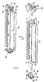
- FIG. 1 only one side plate 30 of the subrack and the two cross members 31 and 34 are schematically indicated in the area of the rear.
- the cross member 34 forms, for example, the lower end, while on the cross member 31 two connector strips facing downwards or upwards can be fastened with the narrow sides facing one another.
- the cross members 31 and 34 are profile sections which are connected with their end faces to the side plates 30 of the subrack.
- the side plates 30 have fastening bores 40.
- projections 36 and 38 protrude on the inside of the side plates 30, which only permit the fixing of the cross members 31 and 34 in connection with the webs, channels 37 and grooves 39 in predetermined positions.
- the cross members 31 and 34 have rows of openings 32, 33 and 35, which are matched in their arrangement and distribution to the mounting dimensions of the connector strips 10.
- the plug strips 10 can be designed as a socket strip or knife contact strip.
- the connector strip 10 is provided with socket contacts into which the blade contacts of the complementary connector strip of inserts can be inserted.
- the insulating body of the connector strip 10 runs on the narrow sides into the mounting flanges 11 and 12, which are provided with the mounting holes 13 for the usual screw mounting.
- the connector strip 10 is fastened by means of two U-shaped retaining clips 20, which, as the vertical arrows in FIG. 2 show, are placed against the fastening flanges 11 and 13 in a mutually directed manner.
- the retaining clips 20 are made as a stamped and bent part made of elastic metal.
- the end leg 22 is bent vertically on the web 21 and the tab 23 is punched out and bent out of the web 21, so that the end leg 22 has the fastening flange 11 or 13 on the side facing the cross member 31 or 34 and the tab 23 on the the cross member 31 or 34 face away.
- the side of the mounting flanges 11 and 13 facing away from the cross member 31 and 34 are closed off at least on two free sides of the tabs 23 by means of webs 14 and 15 or shoulders 16 and 17, so that the tab 23 and thus the retaining clip 20 are held non-rotatably and always occupies the same position on the mounting flange 11 or 13. Since the retaining clips 20 are symmetrical with respect to their central plane running in the longitudinal direction of the connector strip 10, identical retaining clips 20 can be used for both fastening flanges 11 and 13.
- the web 21 of the holding clip 20 merges in the region of the punched-out portion 24 via the remaining outer parts 25 and 26 into the detent spring 27, which is bent approximately parallel to the web 21 by 180 ° on the outside thereof and is bent in a hook shape at the free end.
- the end section serves as a locking lug 28 which, when the locking spring 27 is inserted into an opening 32, 33 or 35 of the cross member 31 or 34, snaps behind it and fixes the plug connector 10 on the cross member 31 or 34.
- the configuration is such that the detent spring 27 and the detent projection 28 run with their broad sides parallel to the long sides of the rectangular openings 32, 33 and 35. The narrow sides of the openings 32, 33 and 35 are smaller than the maximum distance of the locking projection 28 from the locking spring 27 to ensure the locking process.
- the retaining clip 20 is made with the detent spring 27 and the detent projection 28 as a one-piece stamped and bent part made of elastic metal. As the rows of bores 41 and 42 of the cross members 31 and 34 show, the connector strips 10 can still be connected to the cross members 31 and 34 by means of screw connections.
- the distance between the two latching projections 28 of the retaining clips 20 which are plugged onto the two fastening flanges 11 and 13 is greater than the distance between the fastening bores 13 in the fastening flanges 11 and 13 of the connector strip 10
- Distance between the rows of openings 33 and 35 in the cross members 31 and 34 is correspondingly greater than the distance between the rows of bores 41 and 42 in these cross members 31 and 34. Therefore, the screw or snap fastening for the connector strips can be selected. Since the detent springs 27 are outside of the connector strip 10, the cross members 31 and 34 can be between the series of Have openings 33 and 35 and the rows of holes 41 and 42 paragraphs that fix the narrow sides of the connector 10.
- the length of the detent springs 27 with the detent lugs 28 is matched to these shoulders, ie the greater thickness of the cross members 31 and 34 in the area of the openings 32, 33 and 35.
- the bores 41 and 42 are aligned with one another transversely to the cross members 31 and 34 and the average distance between the row of bores 41 and 42 assigned to a narrow side of the connector strip 10 and the row of openings 32, 33 and 35 corresponds to the average distance between the fastening bores 13 of the fastening flange 11 or 12 from the detent spring 27 with the detent projection 28 of the holding clip 20 attached to this fastening flange 11 or 12.
Landscapes
- Engineering & Computer Science (AREA)
- Microelectronics & Electronic Packaging (AREA)
- Details Of Connecting Devices For Male And Female Coupling (AREA)
- Flanged Joints, Insulating Joints, And Other Joints (AREA)
- Fuel Cell (AREA)
- Paper (AREA)
- Connection Of Plates (AREA)
Description
- Die Erfindung betrifft eine Vorrichtung zum Befestigen von Steckerleisten an Trägern, Platten oder dgl., bei der die Steckerleisten an ihren Schmalseiten in Befestigungsflansche auslaufen, auf die Halteklammern aufgesteckt sind, wobei die Halteklammern in Durchbrüche der Träger oder dgl. einführbar sind und diese hintergreifende Rastansätze aufweisen.
- Gerade in Baugruppenträgern ist oft eine Vielzahl von Steckerleisten für Einschübe mit einer komplementären Steckerleiste an den im Bereich der Rückseite des Baugruppenträgers angebrachten Querträgern zu befestigen. Die Steckerleisten laufen an ihren Schmalseiten in Befestigungsflansche mit Befestigungsbohrungen aus, so daß sie mittels Schraubverbindungen an den Querträgern angebracht werden können. Die Querträger weisen dabei Reihen von Bohrungen für die Befestigungsschrauben auf. Diese Art der Befestigung der Steckerleisten erfordert neben den Elementen der Schraubverbindungen einen ganz beachtlichen Montageaufwand.
- Eine Vorrichtung der eingangs beschriebenen Art ist in der FR-A-2 353 970 als bekannt ausgewiesen. Bei dieser bekannten Vorrichtung handelt es sich um eine Halteklammer, mit der ein Stecker an einer Leiterplatte befestigbar ist. Die Halteklammer besitzt einen eingebogenen Endabschnitt, mit dem sie in eine Aussparung an der Stirnseite des Steckers eingelegt wird, und zwei umgebogene seitliche Lappen, mit denen sie seitlich an dem Stecker gehalten ist.
- Es ist Aufgabe der Erfindung, eine Vorrichtung der eingangs erwähnten Art zu schaffen, bei der mit einfachen Befestigungsmitteln die Steckerleiste einfach und schnell an den Querträgern oder anderen Trägern, Platten oder dgl. festgemacht werden kann.
- Diese Aufgabe wird nach der Erfindung dadurch gelöst, daß die Halteklammern in einer Ebene längs zu den Steckerleisten und quer zum Träger oder dgl. U-förmig ausgebildet und in Längsrichtung der Steckerleiste von deren Stirnseiten her gegeneinander gerichtet auf die Befestigungsflansche aufsteckbar sind.
- Bei dieser Vorrichtung brauchen die Halteklammern nur auf die Befestigungsflansche der Steckerleiste aufgesteckt zu werden, dann kann die Steckerleiste mit den Halteklammern an den Querträgern oder dgl. eingerastet werden, wobei die Rastfedern mit den Rastansätzen automatisch die Verbindung der Steckerleiste mit den Querträgern oder dgl. übernehmen. In der Verbindungsstellung können sich die Halteklammern nicht mehr von den Befestigungsflanschen lösen, da die Durchbrüche in den Baugruppenträgern auf die Verteilung der Halteklammern benachbarter Steckerleisten und auf den Abstand der beiden Halteklammern einer Steckerleiste abgestimmt sind. Die Montage erfordert daher nur noch eine einfache Handhabung, die zudem sehr schnell ausführbar ist. Durch Aufheben der Rastverbindungen der Halteklammern mit den Querträgern oder dgl. kann die Steckerleiste jedoch auch wieder gelöst werden.
- Ist nach einer Ausgestaltung vorgesehen, daß die Halteklammern und die Rastfedern mit den Rastansätze jeweils einstückig ausgebildet und als Stanz-Biege-Teil aus einem elastischen Metall hergestellt sind, dann ergeben sich einfache und preisgünstig herstellbare Halteklammern.
- Die Ausgestaltung der Halteklammern ist im einzelnen so, daß die U-förmigen Halteklammern jeweils aus einem an einem Steg abgebogenen Endschenkel und einem aus dem Steg ausgestanzten und ausgebogenen Lappen gebildet sind, wobei die Endschenkel an den den Querträgern oder dgl. zugekehrten Seiten und die Lappen an den den Querträgern oder dgl. abgekehrten Seiten der Befestigungsflansche der Steckerleiste anliegen.
- Eine ausreichend große Federlänge für die Rastfedern und ihre Rastansätze ergibt sich nach einer Ausgestaltung dadurch, daß die den Querträgern oder dgl. abgekehrten Seiten der Stege der U-förmigen Halteklammern außerhalb der Lappen verlängert und um 180° auf die Außenseite des Steges umgebogen als Rastfedern ausgebildet sind, die an ihren freien Enden hakenförmig umgebogen sind und mit den umgebogenen Abschnitten die Rastansätze bilden.
- Um eine eindeutige Stellung der auf die Befestigungsflansche der Steckerleiste aufgesteckten Halteklammern zu erhalten, sieht eine Ausgestaltung vor, daß die Befestigungsflansche der Steckerleiste auf den den Querträgern oder dgl. abgekehrten Seiten die Lappen der U-förmigen Halteklammern an mindestens zwei freien Seiten mittels Stegen oder Absätzen gegen Verdrehen sichern. Die Rastfedern mit den Rastansätzen stehen dann stets in derselben Stellung im Bezug auf die Durchbrüche in den Querträgern oder dgl.
- Ist vorgesehen, daß die Halteklammern in Bezug auf ihre in Längsrichtung der Steckerleiste verlaufende Mittelebene symmetrisch ausgebildet sind, dann sind für beide Schmalseiten der Steckerleiste identische Halteklammern verwendbar.
- Eine wahlweise Verbindung mittels Schraubverbindungen oder Rastverbindungen ist dadurch möglich, daß die Querträger oder dgl. pro Schmalseite der Steckerleiste eine Reihe von Bohrungen und eine Reihe von Durchbrüchen aufweisen, die in Längsrichtung der Querträger oder dgl. ausgerichtet und quer dazu aufeinander ausgerichtet sind, und daß der mittlere Abstand der einander zugeordneten Reihen von Bohrungen und Durchbrüchen dem mittleren Abstand der Befestigungsbohrung im Befestigungsflansch der Steckerleiste und der Rastgeber mit dem Rastansatz der auf diesem Befestigungsflansch aufgesteckten Halteklammer entspricht.
- Die Erfindung wird anhand eines in den Zeichnungen dargestellten Ausführungsbeispiels näher erläutert. Es zeigt:
- Fig. 1 eine perspektivische Teilansicht, die die Befestigung der Steckerleiste mittels Halteklammern an Querträgern eines schematisch angedeuteten Baugruppenträgers verdeutlicht, und
- Fig. 2 in vergrößerter Darstellung die Steckerleiste ohne und mit aufgesteckten Halteklammern.
- In Fig. 1 sind von dem Baugruppenträger nur eine Seitenplatte 30 und die beiden Querträger 31 und 34 im Bereich der Rückseite schematisch angegeben. Der Querträger 34 bildet z.B. den unteren Abschluß, während am Querträger 31 zwei Steckerleisten nach unten bzw. nach oben gerichtet mit den einander zugekehrten Schmalseiten befestigt werden können. Die Querträger 31 und 34 sind Profilabschnitte, die mit ihren Stirnseiten mit den Seitenplatten 30 des Baugruppenträgers verbunden werden. Die Seitenplatten 30 weisen dazu Befestigungsbohrungen 40 auf. Außerdem stehen an den Innenseiten der Seitenplatten 30 Ansätze 36 und 38 vor, die die Festlegung der Querträger 31 und 34 in Verbindung mit den Stegen, Kanälen 37 und Nuten 39 nur in vorgegebenen Positionen zulassen.
- Die Querträger 31 und 34 weisen Reihen von Durchbrüchen 32, 33 und 35 auf, die in ihrer Anordnung und Verteilung auf die Befestigungsmaße der Steckerleisten 10 abgestimmt sind. Die Steckerleisten 10 können als Steckbuchsenleiste oder Messerkontaktleiste ausgebildet sein. Bei dem gezeigten Ausführungsbeispiel ist die Steckerleiste 10 mit Steckbuchsenkontakten versehen, in die Messerkontakte der komplementären Steckerleiste von Einschüben einführbar sind. Der Isolierkörper der Steckerleiste 10 läuft an den Schmalseiten in die Befestigungsflansche 11 und 12 aus, die für die übliche Schraubbefestigung mit den Befestigungsbohrungen 13 versehen sind.
- Die Befestigung der Steckerleiste 10 erfolgt mittels zweier U-förmiger Halteklammern 20, die wie die vertikalen Pfeile in Fig. 2 zeigen, gegeneinander gerichtet auf die Befestigungsflansche 11 und 13 aufgesteckt werden. Die Halteklammern 20 sind als Stanz-Biege-Teil aus elastischem Metall hergestellt. Der Endschenkel 22 ist an dem Steg 21 senkrecht abgebogen und aus dem Steg 21 ist der Lappen 23 ausgestanzt und ausgebogen, so daß der Endschenkel 22 den Befestigungsflansch 11 bzw. 13 an der dem Querträger 31 bzw. 34 zugekehrten Seite und der Lappen 23 an der dem Querträger 31 bzw. 34 abgekehrten Seite anliegen. Die dem Querträger 31 bzw. 34 abgekehrte Seite der Befestigungsflansche 11 bzw. 13 sind zumindest an zwei freien Seiten der Lappen 23 mittels Stege 14 bzw. 15 oder Absätze 16 bzw. 17 abgeschlossen, so daß der Lappen 23 und damit die Halteklammer 20 unverdrehbar gehalten ist und stets dieselbe Position am Befestigungsflansch 11 bzw. 13 einnimmt. Da die Halteklammern 20 zu ihrer in Längsrichtung der Steckerleiste 10 verlaufenden Mittelebene symmetrisch sind, können identische Halteklammern 20 für beide Befestigungsflansche 11 und 13 verwendet werden.
- Der Steg 21 der Halteklammer 20 geht im Bereich der Ausstanzung 24 über die restlichen Außenteile 25 und 26 in die Rastfeder 27 über, die etwa parallel zum Steg 21 um 180° auf dessen Außenseite umgebogen und am freien Ende hakenförmig eingebogen ist. Der Endabschnitt dient dabei als Rastansatz 28, der beim Einstecken der Rastfeder 27 in einen Durchbruch 32, 33 oder 35 des Querträgers 31 oder 34 hinter diesem einrastet und die Steckerleiste 10 an dem Querträger 31 bzw. 34 festlegt. Die Ausgestaltung ist dabei so, daß die Rastfeder 27 und der Rastansatz 28 mit ihren Breitseiten parallel zu den Längsseiten der rechteckförmigen Durchbrüche 32, 33 und 35 verlaufen. Die Schmalseiten der Durchbrüche 32, 33 und 35 sind dabei kleiner als der maximale Abstand des Rastansatzes 28 von der Rastfeder 27, um den Rastvorgang sicherzustellen. Die Halteklammer 20 ist mit der Rastfeder 27 und dem Rastansatz 28 als einstückiges Stanz-Biege-Teil aus elastischem Metall hergestellt. Wie die Reihen von Bohrungen 41 und 42 der Querträger 31 und 34 zeigen, können die Steckerleisten 10 nach wie vor auch mittels Schraubverbindungen mit den Querträgern 31 und 34 verbunden werden.
- Wie aus der Fig. 2 leicht zu ersehen ist, ist der Abstand der beiden Rastansätze 28 der auf die beiden Befestigungsflansche 11 und 13 aufgesteckten Halteklammern 20 größer als der Abstand der Befestigungsbohrungen 13 in den Befestigungsflanschen 11 und 13 der Steckerleiste 10. Daher ist auch der Abstand der Reihen von Durchbrüchen 33 und 35 in den Querträgern 31 und 34 entsprechend größer als der Abstand der Reihen von Bohrungen 41 und 42 in diesen Querträgern 31 und 34. Daher kann wahlweise die Schraub- oder Rastbefestigung für die Steckerleisten gewählt werden. Da die Rastfedern 27 außerhalb der Steckerleiste 10 liegen, können die Querträger 31 und 34 zwischen der Reihe von Durchbrüchen 33 bzw. 35 und den Reihen von Bohrungen 41 bzw. 42 Absätze aufweisen, die die Schmalseiten der Steckerleiste 10 fixieren. Die Länge der Rastfedern 27 mit den Rastansätzen 28 ist auf diese Absätze, d.h. die größere Dicke der Querträger 31 und 34 im Bereich der Durchbrüche 32, 33 und 35 abgestimmt. Die Bohrungen 41 und 42 sind quer zu den Querträgern 31 und 34 aufeinander ausgerichtet und der mittlere Abstand der einer Schmalseite der Steckerleiste 10 zugeordneten Reihe von Bohrungen 41 bzw. 42 von der Reihe von Durchbrüchen 32, 33 bzw. 35 entspricht dem mittleren Abstand der Befestigungsbohrung 13 des Befestigungsflansches 11 bzw. 12 von der Rastfeder 27 mit dem Rastansatz 28 der auf diesen Befestigungsflansch 11 bzw. 12 aufgesteckten Halteklammer 20.
Claims (7)
- Vorrichtung zum Befestigen von Steckerleisten (10) an Trägern (31,34), Platten oder dgl., bei der die Steckerleisten (10) an ihren Schmalseiten in Befestigungsflansche (11,12) auslaufen, auf die Halteklammern (20) mit Rastfedern (27) aufgesteckt sind, die in Durchbrüche (32,33, 35) der Träger (31,34) oder dgl. einführbar sind und diese hintergreifende Rastansätze (28) aufweisen,
dadurch gekennzeichnet,
daß die Halteklammern (20) in einer Ebene längs zu den Steckerleisten (10) und quer zum Träger (31,34) oder dgl. U-förmig ausgebildet und in Längsrichtung der Steckerleiste (10) von deren Stirnseiten her gegeneinander gerichtet auf die Befestigungsflansche (11,12) aufsteckbar sind. - Vorrichtung nach Anspruch 1,
dadurch gekennzeichnet,
daß die Halteklammern (20) und die Rastfedern (27) mit den Rastansätzen (28) jeweils einstückig ausgebildet und als Stanz-Biege-Teil aus einem elastischen Metall hergestellt sind. - Vorrichtung nach Anspruch 1 oder 2,
dadurch gekennzeichnet,
daß die U-förmigen Halteklammern (20) jeweils aus einem an einem Steg (21) abgebogenen Endschenkel (22) und einem aus dem Steg (21) ausgestanzten und ausgebogenen Lappen (23) gebildet sind, wobei die Endschenkel (22) an den den Querträgern (31,34) oder dgl. zugekehrten Seiten und die Lappen (23) an den den Querträgern (31,34) oder dgl. abgekehrten Seiten der Befestigungsflansche (11,12) der Steckerleiste (10) anliegen. - Vorrichtung nach einem der Ansprüche 1 bis 3,
dadurch gekennzeichnet,
daß die den Querträgern (31,34) oder dgl. abgekehrten Seiten der Stege (21) der U-förmigen Halteklammern (20) außerhalb der Lappen (23) verlängert und um 180° auf die Außenseite des Steges (21) umgebogen als Rastfedern (27) ausgebildet sind, die an ihren freien Enden hakenförmig umgebogen sind und mit den umgebogenen Abschnitten die Rastansätze (28) bilden. - Vorrichtung nach einem der Ansprüche 1 bis 4,
dadurch gekennzeichnet,
daß die Befestigungsflansche (11,12) der Steckerleiste (10) auf den den Querträgern (31,34) oder dgl. abgekehrten Seiten die Lappen (23) der U-förmigen Halteklammern (20) an mindestens zwei freien Seiten mittels Stegen (14,15) oder Absätzen (16,17) gegen Verdrehen sichern. - Vorrichtung nach einem der Ansprüche 1 bis 5,
dadurch gekennzeichnet,
daß die Halteklammern (20) in Bezug auf ihre in Längsrichtung der Steckerleiste (10) verlaufende Mittelebene symmetrisch ausgebildet sind. - Vorrichtung nach einem der Ansprüche 1 bis 6,
dadurch gekennzeichnet,
daß die Querträger (31,34) oder dgl. pro Schmalseite der Steckerleiste (10) eine Reihe von Bohrungen (41,42) und eine Reihe von Durchbrüchen (32,33,35) aufweisen, die in Längsrichtung der Querträger (31,34) oder dgl. ausgerichtet und quer dazu aufeinander ausgerichtet sind, und
daß der mittlere Abstand der einander zugeordneten Reihen von Bohrungen (41,42) und Durchbrüchen (32,33,35) dem mittleren Abstand der Befestigungsbohrung (13) im Befestigungsflansch (11,12) der Steckerleiste (10) und der Rastgeber (27) mit dem Rastansatz (28) der auf diesem Befestigungsflansch (11,12) aufgesteckten Halteklammer (20) entspricht.
Priority Applications (3)
| Application Number | Priority Date | Filing Date | Title |
|---|---|---|---|
| DE58908919T DE58908919D1 (de) | 1989-03-30 | 1989-03-30 | Vorrichtung zum Befestigen von Steckerleisten. |
| AT89105601T ATE117466T1 (de) | 1989-03-30 | 1989-03-30 | Vorrichtung zum befestigen von steckerleisten. |
| EP89105601A EP0389656B1 (de) | 1989-03-30 | 1989-03-30 | Vorrichtung zum Befestigen von Steckerleisten |
Applications Claiming Priority (1)
| Application Number | Priority Date | Filing Date | Title |
|---|---|---|---|
| EP89105601A EP0389656B1 (de) | 1989-03-30 | 1989-03-30 | Vorrichtung zum Befestigen von Steckerleisten |
Publications (2)
| Publication Number | Publication Date |
|---|---|
| EP0389656A1 EP0389656A1 (de) | 1990-10-03 |
| EP0389656B1 true EP0389656B1 (de) | 1995-01-18 |
Family
ID=8201149
Family Applications (1)
| Application Number | Title | Priority Date | Filing Date |
|---|---|---|---|
| EP89105601A Expired - Lifetime EP0389656B1 (de) | 1989-03-30 | 1989-03-30 | Vorrichtung zum Befestigen von Steckerleisten |
Country Status (3)
| Country | Link |
|---|---|
| EP (1) | EP0389656B1 (de) |
| AT (1) | ATE117466T1 (de) |
| DE (1) | DE58908919D1 (de) |
Families Citing this family (1)
| Publication number | Priority date | Publication date | Assignee | Title |
|---|---|---|---|---|
| DE19715472B4 (de) * | 1997-04-14 | 2006-06-29 | The Whitaker Corp., Wilmington | Vorrichtung zum Montieren oder Verrasten von Steckverbindern |
Family Cites Families (3)
| Publication number | Priority date | Publication date | Assignee | Title |
|---|---|---|---|---|
| FR2353970A1 (fr) * | 1976-06-03 | 1977-12-30 | Chauchat Jean | Dispositif d'ancrage rapide sur platine de composants electriques ou electroniques |
| US4113337A (en) * | 1976-10-29 | 1978-09-12 | Trw Inc. | Connector constructions and mounting means and hoods therefor |
| BR8206842A (pt) * | 1982-09-30 | 1983-05-03 | Contraves Ag | Unidade de conjuntos de montagem |
-
1989
- 1989-03-30 AT AT89105601T patent/ATE117466T1/de not_active IP Right Cessation
- 1989-03-30 DE DE58908919T patent/DE58908919D1/de not_active Expired - Fee Related
- 1989-03-30 EP EP89105601A patent/EP0389656B1/de not_active Expired - Lifetime
Also Published As
| Publication number | Publication date |
|---|---|
| EP0389656A1 (de) | 1990-10-03 |
| ATE117466T1 (de) | 1995-02-15 |
| DE58908919D1 (de) | 1995-03-02 |
Similar Documents
| Publication | Publication Date | Title |
|---|---|---|
| DE3414591C2 (de) | Abstandhalter für Montageplatten | |
| DE1802589A1 (de) | Elektrische Verbindungsklemme | |
| CH643402A5 (de) | Klemmenblock fuer gedruckte schaltungen. | |
| EP2917974A1 (de) | Modularer steckverbinder | |
| DE19506365A1 (de) | Verbinderbefestigungsanordnung | |
| EP0776077B1 (de) | Vorrichtung zum Befestigen von Zusatzeinrichtungen an Hutschienen | |
| EP0822337B1 (de) | Haltevorrichtung für elektrische Lüfter, insbesondere Kleinstlüfter | |
| DE1271793B (de) | Geraeteeinheit zur Aufnahme von Steckbaugruppen der elektrischen Nachrichtenuebertragungstechnik | |
| EP0264686B1 (de) | Mit Profilschienen eines Baugruppenträgers verbindbare Halteschiene | |
| DE3782729T3 (de) | Verbinder für elektrisches Gerät zum Einrasten auf eine Montageschiene, und elektrisches Gerät geeignet für die Ausführung eines solchen Verbinders. | |
| EP0389656B1 (de) | Vorrichtung zum Befestigen von Steckerleisten | |
| DE29802727U1 (de) | Anschlußleiste und auf eine Anschlußleiste aufsteckbares Überspannungsschutzmagazin | |
| DE69606424T2 (de) | Mechanische kopplungsvorrichtung | |
| WO2019072987A1 (de) | Elektronikgehäuse sowie baugruppenträger | |
| DE29916302U1 (de) | Busleiterabschnitt für ein elektrisches Gerät | |
| DE2539480C2 (de) | Gehäuse für elektrische Bauelemente | |
| DE19913097C1 (de) | Vorrichtung zur Halterung von Anschlußleisten der Telekommunikations-, Steuerungs-, Energie- und Datentechnik | |
| DE3200729C2 (de) | Einrichtung zur Befestigung von Leiterplatten in einem Trägerrahmen | |
| DE3109011C2 (de) | ||
| DE3744190C2 (de) | Verbindungseinrichtung zum Verbinden einer Trägerplatte mit einer Tochterplatte | |
| DE3744189C1 (en) | Connecting device for the mechanical and electrical connection of a motherboard to a secondary board | |
| DE3717219A1 (de) | Vorrichtung zum verbinden einer frontplatte mit einer modulschiene eines baugruppentraegers | |
| DE4305844A1 (de) | Steckverbinder | |
| DE2434579A1 (de) | Haltevorrichtung fuer gedruckte schaltungen tragende steckkarten | |
| EP1374347A1 (de) | Elektrische kontaktanordnung |
Legal Events
| Date | Code | Title | Description |
|---|---|---|---|
| PUAI | Public reference made under article 153(3) epc to a published international application that has entered the european phase |
Free format text: ORIGINAL CODE: 0009012 |
|
| 17P | Request for examination filed |
Effective date: 19891201 |
|
| AK | Designated contracting states |
Kind code of ref document: A1 Designated state(s): AT BE CH DE ES FR GB GR IT LI LU NL SE |
|
| 17Q | First examination report despatched |
Effective date: 19930929 |
|
| GRAA | (expected) grant |
Free format text: ORIGINAL CODE: 0009210 |
|
| AK | Designated contracting states |
Kind code of ref document: B1 Designated state(s): AT BE CH DE ES FR GB GR IT LI LU NL SE |
|
| PG25 | Lapsed in a contracting state [announced via postgrant information from national office to epo] |
Ref country code: ES Free format text: THE PATENT HAS BEEN ANNULLED BY A DECISION OF A NATIONAL AUTHORITY Effective date: 19950118 Ref country code: FR Effective date: 19950118 Ref country code: GB Effective date: 19950118 Ref country code: GR Free format text: LAPSE BECAUSE OF FAILURE TO SUBMIT A TRANSLATION OF THE DESCRIPTION OR TO PAY THE FEE WITHIN THE PRESCRIBED TIME-LIMIT Effective date: 19950118 Ref country code: NL Effective date: 19950118 Ref country code: BE Effective date: 19950118 Ref country code: IT Free format text: LAPSE BECAUSE OF FAILURE TO SUBMIT A TRANSLATION OF THE DESCRIPTION OR TO PAY THE FEE WITHIN THE PRESCRIBED TIME-LIMIT;WARNING: LAPSES OF ITALIAN PATENTS WITH EFFECTIVE DATE BEFORE 2007 MAY HAVE OCCURRED AT ANY TIME BEFORE 2007. THE CORRECT EFFECTIVE DATE MAY BE DIFFERENT FROM THE ONE RECORDED. Effective date: 19950118 |
|
| REF | Corresponds to: |
Ref document number: 117466 Country of ref document: AT Date of ref document: 19950215 Kind code of ref document: T |
|
| REF | Corresponds to: |
Ref document number: 58908919 Country of ref document: DE Date of ref document: 19950302 |
|
| PGFP | Annual fee paid to national office [announced via postgrant information from national office to epo] |
Ref country code: DE Payment date: 19950309 Year of fee payment: 7 |
|
| PG25 | Lapsed in a contracting state [announced via postgrant information from national office to epo] |
Ref country code: AT Effective date: 19950330 |
|
| PG25 | Lapsed in a contracting state [announced via postgrant information from national office to epo] |
Ref country code: LU Free format text: LAPSE BECAUSE OF NON-PAYMENT OF DUE FEES Effective date: 19950331 Ref country code: CH Effective date: 19950331 Ref country code: LI Effective date: 19950331 |
|
| PG25 | Lapsed in a contracting state [announced via postgrant information from national office to epo] |
Ref country code: SE Effective date: 19950418 |
|
| EN | Fr: translation not filed | ||
| NLV1 | Nl: lapsed or annulled due to failure to fulfill the requirements of art. 29p and 29m of the patents act | ||
| GBV | Gb: ep patent (uk) treated as always having been void in accordance with gb section 77(7)/1977 [no translation filed] |
Effective date: 19950118 |
|
| PLBE | No opposition filed within time limit |
Free format text: ORIGINAL CODE: 0009261 |
|
| STAA | Information on the status of an ep patent application or granted ep patent |
Free format text: STATUS: NO OPPOSITION FILED WITHIN TIME LIMIT |
|
| REG | Reference to a national code |
Ref country code: CH Ref legal event code: PL |
|
| 26N | No opposition filed | ||
| PG25 | Lapsed in a contracting state [announced via postgrant information from national office to epo] |
Ref country code: DE Effective date: 19961203 |