EP0389670B1 - Appareil de mesure de la vitesse propre d'un véhicule selon le principe d'un radar Doppler. - Google Patents
Appareil de mesure de la vitesse propre d'un véhicule selon le principe d'un radar Doppler. Download PDFInfo
- Publication number
- EP0389670B1 EP0389670B1 EP89113518A EP89113518A EP0389670B1 EP 0389670 B1 EP0389670 B1 EP 0389670B1 EP 89113518 A EP89113518 A EP 89113518A EP 89113518 A EP89113518 A EP 89113518A EP 0389670 B1 EP0389670 B1 EP 0389670B1
- Authority
- EP
- European Patent Office
- Prior art keywords
- doppler
- mixer
- signal
- doppler frequency
- median filter
- Prior art date
- Legal status (The legal status is an assumption and is not a legal conclusion. Google has not performed a legal analysis and makes no representation as to the accuracy of the status listed.)
- Expired - Lifetime
Links
Images



Classifications
-
- G—PHYSICS
- G01—MEASURING; TESTING
- G01S—RADIO DIRECTION-FINDING; RADIO NAVIGATION; DETERMINING DISTANCE OR VELOCITY BY USE OF RADIO WAVES; LOCATING OR PRESENCE-DETECTING BY USE OF THE REFLECTION OR RERADIATION OF RADIO WAVES; ANALOGOUS ARRANGEMENTS USING OTHER WAVES
- G01S13/00—Systems using the reflection or reradiation of radio waves, e.g. radar systems; Analogous systems using reflection or reradiation of waves whose nature or wavelength is irrelevant or unspecified
- G01S13/02—Systems using reflection of radio waves, e.g. primary radar systems; Analogous systems
- G01S13/50—Systems of measurement based on relative movement of target
- G01S13/58—Velocity or trajectory determination systems; Sense-of-movement determination systems
- G01S13/60—Velocity or trajectory determination systems; Sense-of-movement determination systems wherein the transmitter and receiver are mounted on the moving object, e.g. for determining ground speed, drift angle, ground track
Definitions
- the invention relates to a device for measuring the own speed of a vehicle according to the Doppler radar principle according to the preamble of claim 1.
- the airspeed measurement of a vehicle according to the Doppler radar principle is based on the fact that a difference frequency occurs between the frequency of a wavefront emitted by the vehicle - transmission signal - and that from the surface against which the vehicle is moving in particular horizontally and in turn received by the vehicle .
- the difference frequency is proportional to the relative movement of the vehicle relative to the ground.
- Doppler signal and “Doppler frequency”
- Doppler frequency the signal with the Difference frequency can be understood.
- a Doppler radar module can be used, which comprises an oscillator - gunnoscillator -, a circulator, a mixer, an antenna - horn antenna - and a directional coupler.
- the oscillator generates the high-frequency sinusoidal oscillation, which is fed to the antenna via the circulator.
- the antenna radiates this energy into the room, especially towards the surface on which the vehicle is moving.
- the wave reflected from the background is received again by the antenna, and the corresponding received signal is fed to the mixer via the circulator.
- a part of the transmission energy is additionally fed into the mixer via the directional coupler, so that the reception signal and the transmission signal are superimposed on one another.
- a mixing process takes place in the mixer - mixer diode - to which the transmitted signal and the received signal are applied.
- the Doppler signal is formed as the difference frequency between the frequency of the emitted wave and the frequency of the received reflected wave.
- the Doppler signal is made available via an amplifier for further processing.
- the vehicle speed determined according to the aforementioned measurement principle is therefore associated with a large measurement error.
- a Doppler radar speedometer with a pulse width discriminating device is already known, which is to determine the maximum of the distribution curve of the Doppler signal or the Doppler frequency spectrum (DE-PS 32 19 819).
- This speedometer comprises a Doppler radar sensor which is attached to the vehicle, emits microwaves and receives a part of the waves reflected from the ground and mixes with a part of the emitted waves.
- the resulting Doppler signals are amplified in an amplifier and pulse shaping device, and a Doppler pulse signal is generated.
- the Doppler pulse signal is converted into a digital Doppler signal in a period counter. To evaluate the digital Doppler signals, the output of the period counter serves as an address for a memory.
- An adder increases the contents of the memory at each address addressed for each Doppler pulse signal present until a predetermined number of digital Doppler pulse signals are completely added.
- the abovementioned pulse width discriminating device determines the content of the memory when the nth Doppler pulse signal occurs n 2nd assigned address as a measure of the speed sought.
- This known Doppler radar speedometer has the disadvantage, however, that in order to achieve sufficient accuracy, the digital Doppler signals must be measured and evaluated over longer times if the number of n Doppler pulse signals not too small and thus the determination of the Doppler frequency corresponding to the vehicle speed, which is also referred to as the center frequency, must be inaccurate.
- the measurement and evaluation of the Doppler signals comes at the expense of the dynamics of the method and the Doppler radar speedometer operating according to it. This poor dynamics is particularly disturbing if it is to work in conjunction with an anti-lock device.
- a special antenna designed as a slot antenna waveguide is already known (DE-PS 22 37 139).
- the slot antenna waveguide is aligned with its longitudinal axis parallel to the direction of the speed vector and with its broad sides transverse to it parallel to the earth's surface.
- the radar vibrations which runs somewhat outside the center of the broad side.
- a two-channel Doppler radar device is known (DE-PS 22 37 139), in which with two mixers a Doppler signal from the Radiation in the direction of travel and a Doppler signal from the radiation against the direction of travel are formed. Both signals are combined in the evaluation.
- it is also known to compensate for an error in the Doppler signal by means of vertical vibrations or changes in the distance of the vehicle from the ground by means of a correction signal.
- a further mixer with a diode which receives a quasi-optically mirrored radar radiation that a Doppler shift does not is subjected, but changes its phase position depending on the distance of the antenna to the ground.
- the mixture of the so-called mirrored radiation with the residual signal of the transmitter remaining in the waveguide results in a low-frequency oscillation with which the error occurring in the measurement of the Doppler signal can be compensated.
- the present invention has for its object to quickly and accurately determine a Doppler frequency, which corresponds to the vehicle's own speed, from irregular, strongly fluctuating Doppler spectra. No high additional effort should be required for the corresponding evaluation of the Doppler signals.
- a device according to the preamble of claim 1 is known from the document EP-A3-0095300, while a median filter is known from the document WO-A1-88 / 09537.
- Advantageous developments of the invention are given in claims 2-4.
- the block circuit diagram in FIG. 1 shows a two-channel device for airspeed measurement with two essentially oppositely directed Doppler radar sensors 1 and 2, which are arranged in a so-called Janus head 3.
- the Janus head is firmly connected to a vehicle, not shown, and is moved with it in the direction of travel v.
- Each of the two Doppler signal sensors contains a quadrature mixer, which is indicated by the mixer diodes 4, 5 and 6, 7. This device provides the best prerequisite for the fact that the influences of pitch and height movements of the vehicle are the least.
- the Doppler frequency measurement values are first performed in Schmitt triggers 8-11 fed in which the vibrations of the Doppler frequency measurements are converted into corresponding rectangular pulses A ', B', C ', D'.
- Two D flip-flops 12, 13 are provided to form sign signals which indicate the direction of movement of the vehicle.
- the output of Schmitt trigger 8 is connected to a D input of D flip-flop 12, and an output of Schmitt trigger 9 is connected to a dynamic input of the same D flip-flop.
- An output of the Schmitt trigger 10 is connected to the D input of the D flip-flop 13, whose dynamic input is acted upon by the output of the Schmitt trigger 11.
- an output of the Schmitt trigger 8 is connected to an input of a converter 14 for period measurement and an output of the Schmit trigger 10 is connected to a further converter 15 for period measurement.
- the digital Doppler signal measurement values are obtained as binary numbers in the converters for period measurement. They are supplemented with the sign signals for each channel and fed separately into an evaluation device, generally designated 16.
- the evaluation device contains a memory chain for each channel, which can be implemented in particular by a shift register, and a sorter with which a defined number of discrete Doppler signal measurement values are evaluated to form the median of this Doppler signal measurement value sequence.
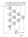
- FIG. 2 A corresponding part for a channel of the evaluation device is shown schematically in FIG. 2.
- the digital Doppler signal measured values X (n), X (n-1) etc. are pushed through on a line 16a.
- X (n) means the nth Doppler signal measured value.
- Delay elements 17 - 20 ensure that the successive Doppler signal measurement values are each delayed by one measurement interval.
- the m Doppler signal measured values, which are sorted in the sorter 27, are therefore present parallel to one another at outlets 21-26 of the line 16a.
- the sorter is constructed in such a way that the sequence of the m Doppler signal measurement values is sorted into a new sequence of increasing importance and from the latter the median (central value) is formed.
- the time delay is built up by a shift register with the input 28 and the memories 29-32, the dynamic input of which is connected via a shift pulse line 33 to shift pulses occurring at each measuring interval.
- the memories 28-32 form a shift register for five measured values.
- the inputs are marked with E and the outputs with A.
- the outputs of the memories for the Doppler signal measured values M (n-1) to M (n-4) and the measured value M (n) are connected to the actual sorter, which is represented by the arrangement of comparators 34 shown in FIG. 43 is formed.
- the comparators are each constructed so that input A is connected to output D and input B to output C if the digital value at input A is greater than the digital value at input B. If this condition is not is met, input A is connected to output C and input B is connected to output D.
- the evaluation device 16 in FIG. 1 comprises for each of the two inputs 45, 46 a sorter with a memory according to FIG. 3, in which the digital Doppler signal measured value T1 or T2 is smoothed according to the median averaging method.
- the evaluation device 16 further comprises an arithmetic mean value image (not designated), which represents the arithmetic mean value of the medians and forms.
- a digital signal of the period of the resulting Doppler frequency from both channels is thus present at an output 47 of the evaluation device 16.
- This period is designated Tj. It can be converted into a speed signal of the own speed by a further converter, which is not shown in FIG. 1. This converter realizes the proportional relationship between the average Doppler frequency derived from the period Tj and the vehicle's own speed.
- FIGS. 4 and 5 illustrate the smoothing effect of the median formation from measured Doppler frequencies, the median representing the mean Doppler frequency with little fluctuation in the course of the continuous evaluation.
- the Doppler signal sensors 1 and 2 shown in FIG. 1, the Schmitt triggers 8-11, the D flip-flops 12 and 13 and the converters 14 and 15 are constructed in accordance with the prior art and function in a manner known per se .
- the converters 14, 15 are used to determine the period of the Doppler signal measurement values. The frequency can then be determined from the reciprocal of the measured period - here after median formation and averaging.
- the D flip-flop 12 or 13 which also belongs to the prior art, represents a memory which takes over the state of the D input when there is a logic "1" at the clock input or dynamic input. The information from the D input is retained at an output Q (see FIG. 1) until the signal at the clock input is "1" and at the D input is "0". Overall, the D flip-flop determines whether the signal A 'or B' lags behind the other signal, and outputs a corresponding sign signal inverted at its output Q or Q, which is a criterion for the direction of movement of the vehicle.
- the following sequence of numbers can be assumed: 5 6 8 3 2 -100 10.
- the new sequence in which the Doppler signal measurements are grouped according to their significance is: -100 2 3 5 6 8 10. This gives the median (central value): 5.
- FIG. 6 shows how the mixer diodes, for example 4, 5 of the quadrature mixer, are arranged offset on one another on a line 48 between an oscillator 49 and an antenna 50.
- the distance l1 of the couplings of the two mixer diodes 4 and 5 at the positions x and y of the line 48 is an odd multiple of ⁇ 8th .
- the antenna 50 moves at the speed v.
Landscapes
- Engineering & Computer Science (AREA)
- Radar, Positioning & Navigation (AREA)
- Remote Sensing (AREA)
- Computer Networks & Wireless Communication (AREA)
- Physics & Mathematics (AREA)
- General Physics & Mathematics (AREA)
- Radar Systems Or Details Thereof (AREA)
Claims (4)
- Dispositif pour la mesure de la vitesse propre d'un véhicule automobile selon le principe d'un radar à effet Doppler-Fizeau, le dispositif comportant un détecteur (1, 2) de radar à effet Doppler-Fizeau qui lui est associé, un mélangeur (4, 5 ; 6, 7) alimenté en des microondes à la fréquence d'émission ainsi que par des microondes reçues par le détecteur (1, 2) de radar à effet Doppler-Fizeau, un formateur (8, 9 ; 10, 11) d'impulsions relié à une sortie du mélangeur (4, 5 ; 6, 7), un mesureur (14, 15) de durée des périodes monté après le formateur (8, 9 ; 10, 11) d'impulsions et qui produit, pour chaque période numérisée, une valeur numérique de fréquence Doppler-Fizeau;dispositif caractérisé en ce qu'un dispositif (16) d'analyse et d'exploitation, monté en aval du mesureur (14, 15) de durée de période et qui, à partir d'un nombre prédéterminé de valeurs de fréquence Doppler-Fizeau, calcule une mesure constituant la moyenne de la vitesse cherchée et englobe un filtre médian dont les entrées sont alimentées de manière flottante par une suite continue de valeurs numériques de fréquence Doppler (T1, T2) et en ce que le filtre médian est associé à un agencement (28-32) de registre à décalage dont l'entrée (28) est alimentée par les valeurs numériques (T1, T2) de mesure de fréquence Doppler et dont les étages (28-32) du registre à décalage sont cadencés à chaque intervalle de mesure (période de mesure) avec une cadence d'horloge de décalage et en ce que le filtre médian comporte des comparateurs (34-44), dont les entrées sont reliées aux sorties des étages (28-32) du registre à décalage ainsi qu'entre elles de manière qu'elles éliminent, par filtrage des valeurs (T1, T2) de fréquence numérique Doppler mémorisées dans les étages (28-32) du registre à décalage, la valeur numérique de fréquence Doppler représentant la valeur médiane ou moyenne.
- Dispositif selon la revendication 1, caractérisé en ce qu'un mélangeur à quadrature de phase est prévu avec deux diodes mélangeuses (4, 5) couplées, avec un décalage d'un multiple impair de λ/8, par rapport à la fréquence d'émission, sur un conducteur dans le détecteur de radar à effet Doppler-Fizeau (1 ou 2) entre l'oscillateur (49) et l'antenne (50), et en ce que deux signaux Doppler (A, B ou C, D) des deux diodes mélangeuses sont introduites dans un discriminateur de signe, qui engendre un signal de signe correspondant à la relation de rapport entre les phases entre les deux signaux Doppler (A, B ou C, D), signal qui, avec la valeur de fréquence Doppler numérique correspondante est acheminéà l'aide du filtre médianau dispositif (16) d'analyse et d'exploitation.
- Dispositif selon la revendication 2, caractérisé en ce que le discriminateur de signe consiste en une bascule D-"Flip-Flop" (12 ou 13) comportant une entrée statique (D) et une entrée dynamique qui sont en liaison avec chacune des deux diodes mélangeuses (4, 5 ou 6, 7) du mélangeur à quadrature de phase.
- Dispositif selon les revendications 2 à 3, comportant un détecteur de radar à effet Doppler-Fizeau à deux canaux avec des mélangeurs en quadrature de phase, dispositif caractérisé en ce que, dans chaque canal, un mesureur de durée de période (convertisseur 14 ou 15) ainsi qu'un discriminateur de signe (bascule D 12 ou 13) sont placés avant un dispositif (16) d'analyse et d'exploitation comportant un filtre médian pour chaque canal et en ce que les sorties du filtre médian sont reliées à un formateur de valeur arithmétique moyenne, dont la valeur moyenne constitue une mesure de la vitesse propre recherchée (vitesse horizontale).
Applications Claiming Priority (2)
| Application Number | Priority Date | Filing Date | Title |
|---|---|---|---|
| DE3909644A DE3909644A1 (de) | 1989-03-23 | 1989-03-23 | Verfahren und vorrichtung zur eigengeschwindigkeitsmessung eines fahrzeugs nach dem dopplerradarprinzip |
| DE3909644 | 1989-03-23 |
Publications (3)
| Publication Number | Publication Date |
|---|---|
| EP0389670A2 EP0389670A2 (fr) | 1990-10-03 |
| EP0389670A3 EP0389670A3 (fr) | 1991-03-27 |
| EP0389670B1 true EP0389670B1 (fr) | 1995-01-04 |
Family
ID=6377092
Family Applications (1)
| Application Number | Title | Priority Date | Filing Date |
|---|---|---|---|
| EP89113518A Expired - Lifetime EP0389670B1 (fr) | 1989-03-23 | 1989-07-22 | Appareil de mesure de la vitesse propre d'un véhicule selon le principe d'un radar Doppler. |
Country Status (3)
| Country | Link |
|---|---|
| US (1) | US4980633A (fr) |
| EP (1) | EP0389670B1 (fr) |
| DE (2) | DE3909644A1 (fr) |
Cited By (1)
| Publication number | Priority date | Publication date | Assignee | Title |
|---|---|---|---|---|
| CN109658715A (zh) * | 2019-01-31 | 2019-04-19 | 厦门精益远达智能科技有限公司 | 多车道的车流量统计方法、装置、设备和存储介质 |
Families Citing this family (18)
| Publication number | Priority date | Publication date | Assignee | Title |
|---|---|---|---|---|
| JPH08160129A (ja) * | 1994-12-05 | 1996-06-21 | Uniden Corp | 速度検出装置 |
| DE19502873C2 (de) * | 1995-01-30 | 1998-10-08 | Deuta Mestechnik Gmbh Berlin | Verfahren und Vorrichtung zur berührungslosen Ermittlung der Bewegungsgrößen von Fahrzeugen |
| US5621413A (en) * | 1995-06-27 | 1997-04-15 | Motorola Inc. | Vehicle-ground surface measurement system |
| US6230107B1 (en) * | 1996-03-29 | 2001-05-08 | Komatsu Ltd. | Vehicle speed detection system |
| BE1012479A7 (nl) | 1999-02-23 | 2000-11-07 | Leuven K U Res & Dev | Beweegbare sproeiboom. |
| DE19914486C1 (de) * | 1999-03-30 | 2000-05-18 | Fraunhofer Ges Forschung | Vorrichtung und Verfahren zur berührungslosen Geschwindigkeitsmessung auf Oberflächen |
| JP3562408B2 (ja) * | 1999-11-10 | 2004-09-08 | 株式会社デンソー | レーダ装置特性検出装置及び記録媒体 |
| US6580386B1 (en) * | 2001-08-16 | 2003-06-17 | Applied Concepts, Inc. | System and method for processing radar data |
| US7218271B2 (en) * | 2001-08-16 | 2007-05-15 | Applied Concepts, Inc. | System and method for determining patrol speed |
| DE10340227A1 (de) * | 2003-08-28 | 2005-03-31 | Siemens Ag | Verfahren zur Auswertung von Dopplersignalen eines Mikrowellen-Dopplerradars zur Ermittlung der Geschwindigkeit über Grund |
| US9500747B2 (en) * | 2012-01-10 | 2016-11-22 | Mitsubishi Electric Corporation | Travel distance measurement device |
| US10247816B1 (en) * | 2015-07-06 | 2019-04-02 | Apple Inc. | Apparatus and method to measure slip and velocity |
| US10832426B2 (en) | 2015-09-24 | 2020-11-10 | Apple Inc. | Systems and methods for surface monitoring |
| WO2017053407A1 (fr) | 2015-09-24 | 2017-03-30 | Quovard Management Llc | Systèmes et procédés de localisation à l'aide d'une imagerie de surface |
| US10705105B2 (en) | 2017-07-21 | 2020-07-07 | Applied Concepts, Inc. | Absolute speed detector |
| DE102022114239A1 (de) * | 2022-06-07 | 2023-12-07 | Itk Engineering Gmbh | Radarsystem mit zwei Radarsensoren, Landfahrzeug und Verfahren |
| CN116626341A (zh) * | 2023-05-24 | 2023-08-22 | 广州市方瞳科技有限责任公司 | 一种用于汽车abs轮速传感器性能快速分析方法与装备 |
| CN120214776B (zh) * | 2025-05-28 | 2025-08-12 | 浙江芯源交通电子有限公司 | 应用于车载便携移动警示屏的车载测速方法及装置 |
Family Cites Families (10)
| Publication number | Priority date | Publication date | Assignee | Title |
|---|---|---|---|---|
| US4107680A (en) * | 1976-11-01 | 1978-08-15 | Rca Corporation | Digitally processed radar speed sensor |
| US4319245A (en) * | 1980-05-29 | 1982-03-09 | Rca Corporation | Doppler signal processing apparatus |
| DE3035374A1 (de) * | 1980-09-19 | 1982-05-19 | Licentia Patent-Verwaltungs-Gmbh, 6000 Frankfurt | Fahzeug-dopplerradargeraet |
| EP0095300B1 (fr) * | 1982-05-25 | 1987-10-21 | Plessey Overseas Limited | Dispositif de radar Doppler monté sur un véhicule |
| US4489321A (en) * | 1983-05-05 | 1984-12-18 | Deere & Company | Radar ground speed sensing system |
| US4633252A (en) * | 1983-08-29 | 1986-12-30 | Dickey-John Corporation | Radar velocity sensor |
| US4728954A (en) * | 1984-12-20 | 1988-03-01 | Deere & Company | Ground velocity sensor with drop-out detection |
| US4672567A (en) * | 1985-02-19 | 1987-06-09 | Allied Corporation | Median filter for reducing data error in distance measuring equipment |
| US4818999A (en) * | 1986-10-29 | 1989-04-04 | The United States Of America As Represented By The Administrator Of The National Aeronautics And Space Administration | Method and apparatus for measuring frequency and phase difference |
| EP0316402A4 (fr) * | 1987-05-26 | 1989-09-19 | Sundstrand Data Control | Filtre median rapide. |
-
1989
- 1989-03-23 DE DE3909644A patent/DE3909644A1/de not_active Withdrawn
- 1989-07-22 DE DE58908859T patent/DE58908859D1/de not_active Expired - Fee Related
- 1989-07-22 EP EP89113518A patent/EP0389670B1/fr not_active Expired - Lifetime
-
1990
- 1990-03-02 US US07/488,337 patent/US4980633A/en not_active Expired - Fee Related
Cited By (2)
| Publication number | Priority date | Publication date | Assignee | Title |
|---|---|---|---|---|
| CN109658715A (zh) * | 2019-01-31 | 2019-04-19 | 厦门精益远达智能科技有限公司 | 多车道的车流量统计方法、装置、设备和存储介质 |
| CN109658715B (zh) * | 2019-01-31 | 2021-01-22 | 厦门精益远达智能科技有限公司 | 多车道的车流量统计方法、装置、设备和存储介质 |
Also Published As
| Publication number | Publication date |
|---|---|
| EP0389670A2 (fr) | 1990-10-03 |
| DE3909644A1 (de) | 1990-09-27 |
| EP0389670A3 (fr) | 1991-03-27 |
| DE58908859D1 (de) | 1995-02-16 |
| US4980633A (en) | 1990-12-25 |
Similar Documents
| Publication | Publication Date | Title |
|---|---|---|
| EP0389670B1 (fr) | Appareil de mesure de la vitesse propre d'un véhicule selon le principe d'un radar Doppler. | |
| DE4242700C2 (de) | Verfahren zur Messung des Abstandes und der Geschwindigkeit von Objekten | |
| DE102009000468B4 (de) | Radarverfahren und -systeme mit Rampensequenzen | |
| DE69923815T2 (de) | FM-CW Radarvorrichtung | |
| EP0677172B1 (fr) | Procede informatise faisant appel a un radar, pour mesurer les distances et les vitesses relatives entre un vehicule et des obstacles se trouvant en face de lui | |
| DE2410500C3 (de) | Pulsradarsystem linear zeitverknüpfter Tragerfrequenz mit hohem Entfernungsauflösungsvermögen | |
| EP2507649B1 (fr) | Procédé de détermination univoque d'une distance et/ou d'une vitesse relative d'un objet, système d'assistance au conducteur et véhicule à moteur | |
| EP0882957B1 (fr) | Procédé de mesure du niveau d'un matériau dans un réservoir suivant le principe radar | |
| EP1324067B1 (fr) | Procédé et circuit pour la mesure de la distance d'un objet | |
| EP3418700A1 (fr) | Appareil de radiodétection de niveau de remplissage à adaptation automatique de la fréquence | |
| DE3789830T3 (de) | Radargerät zur Messung der Entfernung zu einer Oberfläche. | |
| EP0882956A2 (fr) | Procédé de mesure du niveau d'un matériau dans un réservoir suivant le principle radar | |
| EP0535196B1 (fr) | Procede et dispositif pour la mesure de distance selon le principe de la retroreflection | |
| DE19734713A1 (de) | Radar-Entfernungsmeßeinrichtung | |
| DE3134243A1 (de) | Verfahren und vorrichtung zum ermitteln der position eines gegenstandes in einem begrenzten raum | |
| DE4040572A1 (de) | Verfahren zur messung des abstandes und der geschwindigkeit eines objekts | |
| EP0776486B1 (fr) | Capteur radar | |
| EP3811103B1 (fr) | Dispositif radar et procédé de fonctionnement d'un dispositif radar | |
| WO2019101466A1 (fr) | Procédé d'évaluation de données de mesure radar d'un système de mesure radar mobile | |
| DE112014006066T5 (de) | Radarvorrichtung sowie Distanz- und Geschwindigkeitsmessverfahren | |
| DE2756413C3 (de) | Gerät zur Messung des Abstandes und der Näherungsgeschwindigkeit oder der Entfernungsgeschwindigkeit eines beweglichen Zieles | |
| DE69701260T2 (de) | Verfahren, vorrichtung und gerät zum messen des abstands zwischen einem gegenstand und einem gerät | |
| DE102019132354A1 (de) | FMCW-basiertes Abstandsmessgerät | |
| DE2305941B2 (de) | Fahrzeughindernisradar mit abwechselndem FM/CW- und CW-Betrieb zur Entfernungs- bzw. Geschwindigkeitsmessung | |
| DE888567C (de) | Radargeraet mit Ausschaltung der festen Echos |
Legal Events
| Date | Code | Title | Description |
|---|---|---|---|
| PUAI | Public reference made under article 153(3) epc to a published international application that has entered the european phase |
Free format text: ORIGINAL CODE: 0009012 |
|
| AK | Designated contracting states |
Kind code of ref document: A2 Designated state(s): DE FR GB IT SE |
|
| PUAL | Search report despatched |
Free format text: ORIGINAL CODE: 0009013 |
|
| AK | Designated contracting states |
Kind code of ref document: A3 Designated state(s): DE FR GB IT SE |
|
| 17P | Request for examination filed |
Effective date: 19910412 |
|
| 17Q | First examination report despatched |
Effective date: 19930614 |
|
| GRAA | (expected) grant |
Free format text: ORIGINAL CODE: 0009210 |
|
| AK | Designated contracting states |
Kind code of ref document: B1 Designated state(s): DE FR GB IT SE |
|
| PG25 | Lapsed in a contracting state [announced via postgrant information from national office to epo] |
Ref country code: FR Effective date: 19950104 Ref country code: GB Effective date: 19950104 Ref country code: IT Free format text: LAPSE BECAUSE OF FAILURE TO SUBMIT A TRANSLATION OF THE DESCRIPTION OR TO PAY THE FEE WITHIN THE PRE;WARNING: LAPSES OF ITALIAN PATENTS WITH EFFECTIVE DATE BEFORE 2007 MAY HAVE OCCURRED AT ANY TIME BEFORE 2007. THE CORRECT EFFECTIVE DATE MAY BE DIFFERENT FROM THE ONE RECORDED.SCRIBED TIME-LIMIT Effective date: 19950104 |
|
| REF | Corresponds to: |
Ref document number: 58908859 Country of ref document: DE Date of ref document: 19950216 |
|
| PG25 | Lapsed in a contracting state [announced via postgrant information from national office to epo] |
Ref country code: SE Effective date: 19950404 |
|
| EN | Fr: translation not filed | ||
| GBV | Gb: ep patent (uk) treated as always having been void in accordance with gb section 77(7)/1977 [no translation filed] |
Effective date: 19950104 |
|
| PLBE | No opposition filed within time limit |
Free format text: ORIGINAL CODE: 0009261 |
|
| STAA | Information on the status of an ep patent application or granted ep patent |
Free format text: STATUS: NO OPPOSITION FILED WITHIN TIME LIMIT |
|
| 26N | No opposition filed | ||
| PGFP | Annual fee paid to national office [announced via postgrant information from national office to epo] |
Ref country code: DE Payment date: 20020916 Year of fee payment: 14 |
|
| PG25 | Lapsed in a contracting state [announced via postgrant information from national office to epo] |
Ref country code: DE Free format text: LAPSE BECAUSE OF NON-PAYMENT OF DUE FEES Effective date: 20040203 |