EP0389866A2 - Châssis pour wagons ferroviaires, notamment pour wagons-citernes ou wagons fermés pour produits en vrac - Google Patents
Châssis pour wagons ferroviaires, notamment pour wagons-citernes ou wagons fermés pour produits en vrac Download PDFInfo
- Publication number
- EP0389866A2 EP0389866A2 EP90104791A EP90104791A EP0389866A2 EP 0389866 A2 EP0389866 A2 EP 0389866A2 EP 90104791 A EP90104791 A EP 90104791A EP 90104791 A EP90104791 A EP 90104791A EP 0389866 A2 EP0389866 A2 EP 0389866A2
- Authority
- EP
- European Patent Office
- Prior art keywords
- base frame
- long
- strut
- struts
- diagonal
- Prior art date
- Legal status (The legal status is an assumption and is not a legal conclusion. Google has not performed a legal analysis and makes no representation as to the accuracy of the status listed.)
- Granted
Links
- 239000000872 buffer Substances 0.000 claims abstract description 29
- 238000005452 bending Methods 0.000 claims abstract description 10
- 230000002441 reversible effect Effects 0.000 claims abstract description 5
- 238000010521 absorption reaction Methods 0.000 claims abstract description 3
- 230000001133 acceleration Effects 0.000 description 3
- 230000000712 assembly Effects 0.000 description 2
- 238000000429 assembly Methods 0.000 description 2
- 238000010276 construction Methods 0.000 description 2
- 230000008878 coupling Effects 0.000 description 2
- 238000010168 coupling process Methods 0.000 description 2
- 238000005859 coupling reaction Methods 0.000 description 2
- 238000013016 damping Methods 0.000 description 2
- 238000011161 development Methods 0.000 description 1
- 230000018109 developmental process Effects 0.000 description 1
- 230000000694 effects Effects 0.000 description 1
- 238000007667 floating Methods 0.000 description 1
- 238000003780 insertion Methods 0.000 description 1
- 230000037431 insertion Effects 0.000 description 1
- 230000035939 shock Effects 0.000 description 1
- 230000003068 static effect Effects 0.000 description 1
- 238000009827 uniform distribution Methods 0.000 description 1
Images


Classifications
-
- B—PERFORMING OPERATIONS; TRANSPORTING
- B61—RAILWAYS
- B61D—BODY DETAILS OR KINDS OF RAILWAY VEHICLES
- B61D7/00—Hopper cars
- B61D7/02—Hopper cars with discharge openings in the bottoms
-
- B—PERFORMING OPERATIONS; TRANSPORTING
- B61—RAILWAYS
- B61D—BODY DETAILS OR KINDS OF RAILWAY VEHICLES
- B61D5/00—Tank wagons for carrying fluent materials
- B61D5/06—Mounting of tanks; Integral bodies and frames
-
- B—PERFORMING OPERATIONS; TRANSPORTING
- B61—RAILWAYS
- B61F—RAIL VEHICLE SUSPENSIONS, e.g. UNDERFRAMES, BOGIES OR ARRANGEMENTS OF WHEEL AXLES; RAIL VEHICLES FOR USE ON TRACKS OF DIFFERENT WIDTH; PREVENTING DERAILING OF RAIL VEHICLES; WHEEL GUARDS, OBSTRUCTION REMOVERS OR THE LIKE FOR RAIL VEHICLES
- B61F1/00—Underframes
- B61F1/04—Underframes of triangulated type
Definitions
- the invention relates to a base frame for rail-bound freight wagons, in particular tank wagons and closed bulk goods wagons, according to the preamble of claim 1.
- Every rail-bound freight wagon is connected to a chassis for transport purposes. This applies to freight wagons with fixed bodies and container wagons with detachable bodies as well as for tank wagons and closed bulk goods wagons.
- the application of the invention relates only to the freight car with a base.
- the known tank wagons can be divided into two construction concepts, tank wagons without a base and tank wagons with a base.
- the following discussion of the state of the art takes into account the state of the art of the underframe-free tank wagons in the first section for the sake of incorporating the technological environment.
- the boiler In the tank wagons without an underframe, the boiler is designed to be so stable that it can absorb the operationally occurring forces and tensions, in particular from shock loads, without undue deformation. With this design, a reduction in weight or improved adaptability of the chassis arranged on the boiler to the track conditions can be achieved for certain applications.
- the connection of the assemblies carrying the train and push device and the bogies to the boiler is problematic, whereby the introduction and reduction of the forces and energy from the buffer joint and in the event of lifting is ensured without excess voltage and inadmissible deformations within the construction got to.
- a base frame for rail-bound tank wagons of conventional design with two continuous middle long beams is known as a middle section, at each end of which a head section with outer long beams and cross beams connecting them is arranged.
- the boiler is supported at its ends on the one hand in transverse saddles arranged transversely to the longitudinal direction of the boiler on the underframe and on the other hand connected to the underframe via lateral saddle support bars which absorb the acceleration forces in the longitudinal direction of the wagon.
- the boiler is in the usual way via side saddle rails, which absorb the forces from the deceleration and acceleration of the tank car, and cross saddles, the static Take up the weight load and the forces occurring transversely to the longitudinal direction of the wagon, connected to the underframe.
- the tank wagon is through this rigid connection between the boiler and the base frame thus also relatively torsion-resistant.
- the connection points between the boiler and the base frame must also absorb the loads caused by the acceleration and weight forces.
- the invention has for its object to provide a base frame for freight wagons, especially for tank wagons and closed bulk goods wagons, in such a way that the connection points between the base frame and the body are relieved in the event of buffer impacts on the side of the buffer joint and the buffer forces that occur are reduced.
- the underframe 1 is to be designed for the loads in the longitudinal direction, in particular from buffer joints.
- a rail-bound freight wagon has a structure 15 and a base frame 1, which is formed by two head sections 2 and a middle section 3.
- the middle section 3 is connected at its two ends A, B to a head section 2.
- the head section 2 consists of a side cross member 5 receiving the side buffers 4, the outer long members 6 and the main cross member 7.
- the cross members 5, 7 arranged in the vehicle transverse direction, at least one cross member 5, 7 is reversibly flexibly connected to the outer long members 6 about a vertical axis. Arrangements with one or more transverse beams 5, 7 which are flexible about a vertical axis can be formed.
- the outer long beams 6 of the head section 2 can be designed to be reversibly flexible.
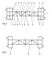
- the middle section 3 consists of two long beams 8 which are arranged at a distance in the horizontal plane and which are connected by a bracing 9.
- the strut bandage 9 is designed and arranged in such a way that it couples the long beams 8 to one another in a flexible manner and forces them to undergo reversible deformations, at least in the horizontal plane, in particular to bending deformations transverse to the longitudinal direction of the underframe.
- the bracing 9 is designed as a horizontal bracing 9 aligned as a horizontal plane or as a spatial bracing 9 and has diagonal braces 10 aligned at an angle to the long beams 8, which are at an angle smaller or greater than 90 ° with respect to the longitudinal direction with respect to the horizontal plane the long beam 8 connects. Furthermore, the strut bandage 9 has support struts 11 which are oriented transversely to the long beams 8 and connect the long beams 8 at right angles to the horizontal plane. The diagonal struts 10 and support struts 11 are arranged in an at least partially repeating sequence within the strut assembly 9, wherein individual fields arise.
- the diagonal struts 10 of the strut assembly 9 follow one another with respect to the arrangement in the longitudinal direction of the underframe 1 at least in regions with an opposite angle. At least in some areas within the underframe 1, at least one diagonal strut 10 connecting the long members 8 is provided between two support struts 11 connecting the long members 8, the diagonal struts 10 arranged immediately on both sides of a support strut 11 being at least partially within the underframe 1 with an opposite angle with respect to the longitudinal direction a long beam 8 are arranged.
- the diagonal strut (s) 10 and the support strut (s) 11 assigned to them expediently each engage in a common node 12 on the long beam 8.
- At least one diagonal strut 10 and an adjacent support strut 11 are attached to the long beam 8 in the common node 12.
- the diagonal struts 10 and the support struts 11 within the strut assembly 9 are connected to the long girders 8 in such a way that from each junction 12 of a long girder 8 there is a support strut 11 aligned transversely to the long girders 8 and at least one, but preferably two, diagonally oriented diagonal struts 10 have adjacent long beams 8 and are attached to this.
- the support strut 11 is attached at its other end to the adjacent long beam 8 in a support point 13.
- the or selected nodes 12 and / or support points 13 can be designed as joints, both functional joints and material-elastic joints being executable.
- two support struts 11 aligned transversely to the long beams 8 can follow one another directly, thus creating a space in the base frame 1 for the outlet fittings.
- Each head section 2 has a saddle 14 for connecting the structure 15 to the underframe 1, such that each saddle 14a, 14b defines the end A, B of the structure 15 supported by it in the direction of the transverse median plane of the underframe 1, the ends A , B of the structure 15 in the direction of the respectively associated end A, B of the base frame 1 are held longitudinally displaceably against the base frame 1.
- the forces from a buffer joint are thus introduced via the base frame 1 into the end of the structure 15 facing away from the buffer joint.
- the structure 15 has at its end A an abutment piece 16a on the body side, to which an abutment-side abutment 17a is assigned and at its end B an abutment piece 16b on the abutment side, to which an abutment-side abutment 17b is associated.
- the stop pieces 16a, 16b and the abutments 17a, 17b are arranged above the level of the force introduction, which is at the level of the side buffers.
- an arrangement of the stop pieces 16a, 16b and the abutment 17a, 17b respectively assigned to them can be arranged in the plane of the force application, i. H. in the level of the page buffer 4.
- the invention is explained below when it is subjected to an impact impact.
- the impact energy is first of all reduced by the side buffers 4 in the power flow, as a rule four side buffers 4 are involved in the impact, within the limits of which the maximum total buffer work is reduced.
- the impact force or energy from the buffer impact becomes exhausted Buffer stroke passed through the underframe 1, a further part of the impact energy being absorbed or reduced in the underframe 1 essentially by deformation work, but also by friction and heat, etc., depending on the design, the spring constant and the damping property of the underframe 1 .
- the base frame 1 according to the invention as a bending structure which is flexible and resilient in the longitudinal direction, considerable portions of the impact energy are absorbed and impact force is reduced.
- the energy absorption and the reduction of the impact force take place essentially by deliberately reversible bending of the structure or of parts of the structure of the head sections 2 (cross beams 5, 7; outer long beams 6 and possibly further beams) and / or the middle section 3 (long beams 8 and possibly further ones) Carrier) of the underframe 1.
- the longwall brace 9 connects and couples the long girders 8 of the middle section 3 in such a flexible manner that they are forced to targeted, reversible bending deformations transverse to the longitudinal direction of the underframe 1.
- the elongated beam 8 is bent outwards at the junction 12 by a certain bending path ⁇ s in the event of an impact impact.
- the opposite long beam 8 is coupled with the support strut 11 in the support point 13, the latter is displaced inwards by the same distance ⁇ s (FIG. 2).
- a base frame 1 is formed with a plurality of flexible cross members 5, 7 and the strut assembly 9 is arranged axially symmetrically.
- Fig. 5 also shows schematically an embodiment of a face brace 9 in axial symmetry.
- FIG. 1 is, like a further exemplary embodiment according to FIG. 6, of central symmetry.
- a further embodiment according to FIG. 6 has diagonal struts of different lengths within the strut assembly 9 and no symmetry with respect to the transverse center plane.
- FIG. 8 Another embodiment according to FIG. 8 has continuous outer long beams 6.
- the outer long beams 6 are connected to the neighboring long beams 8 via support struts 11.
- the underframe 1 likewise has continuous outer long beams 6, which are connected to an adjacent long beam 8 via diagonal struts 10 and supporting struts 11, opposite nodes 12 being positively arranged relative to one another, i. H. are decoupled in the event of bending in the event of opposing deflection.
- the underframe 1 has at least two reversibly flexible long beams 8, which are coupled to one another by a strut assembly 9 with diagonal struts 10 and support struts 11.
Landscapes
- Engineering & Computer Science (AREA)
- Mechanical Engineering (AREA)
- Transportation (AREA)
- Vibration Dampers (AREA)
- Packaging Of Machine Parts And Wound Products (AREA)
Priority Applications (1)
| Application Number | Priority Date | Filing Date | Title |
|---|---|---|---|
| AT90104791T ATE94485T1 (de) | 1989-03-25 | 1990-03-14 | Untergestell fuer schienengebundene gueterwagen, insbesondere fuer kesselwagen und geschlossene schuettgutwagen. |
Applications Claiming Priority (4)
| Application Number | Priority Date | Filing Date | Title |
|---|---|---|---|
| DE19893909883 DE3909883A1 (de) | 1989-03-25 | 1989-03-25 | Abstuetzung fuer einen behaelter auf dem untergestell eines eisenbahngueterwagens |
| DE3909883 | 1989-03-25 | ||
| DE19893940650 DE3940650C1 (fr) | 1989-12-08 | 1989-12-08 | |
| DE3940650 | 1989-12-08 |
Publications (3)
| Publication Number | Publication Date |
|---|---|
| EP0389866A2 true EP0389866A2 (fr) | 1990-10-03 |
| EP0389866A3 EP0389866A3 (fr) | 1991-10-09 |
| EP0389866B1 EP0389866B1 (fr) | 1993-09-15 |
Family
ID=25879222
Family Applications (2)
| Application Number | Title | Priority Date | Filing Date |
|---|---|---|---|
| EP90104792A Expired - Lifetime EP0389867B1 (fr) | 1989-03-25 | 1990-03-14 | Etayage d'une citerne sur le châssis d'un wagon ferroviaire |
| EP90104791A Expired - Lifetime EP0389866B1 (fr) | 1989-03-25 | 1990-03-14 | Châssis pour wagons ferroviaires, notamment pour wagons-citernes ou wagons fermés pour produits en vrac |
Family Applications Before (1)
| Application Number | Title | Priority Date | Filing Date |
|---|---|---|---|
| EP90104792A Expired - Lifetime EP0389867B1 (fr) | 1989-03-25 | 1990-03-14 | Etayage d'une citerne sur le châssis d'un wagon ferroviaire |
Country Status (4)
| Country | Link |
|---|---|
| EP (2) | EP0389867B1 (fr) |
| DD (1) | DD293556A5 (fr) |
| DE (1) | DE59005575D1 (fr) |
| FI (2) | FI901461A7 (fr) |
Cited By (3)
| Publication number | Priority date | Publication date | Assignee | Title |
|---|---|---|---|---|
| US6357363B1 (en) | 2000-04-19 | 2002-03-19 | Gunderson, Inc. | Railroad tank car |
| EP1369330A1 (fr) * | 2002-06-07 | 2003-12-10 | Robel Bahnbaumaschinen GmbH | Véhicule d'entretien |
| CN106740949A (zh) * | 2016-12-20 | 2017-05-31 | 中车山东机车车辆有限公司 | 一种有底架罐车的底架装置 |
Families Citing this family (3)
| Publication number | Priority date | Publication date | Assignee | Title |
|---|---|---|---|---|
| DE19704463A1 (de) * | 1997-02-06 | 1998-08-13 | Linke Hofmann Busch | Schienengebundener Güterwagen, insbesondere Kesselwagen |
| RU180705U1 (ru) * | 2018-02-05 | 2018-06-21 | РЕЙЛ 1520 АйПи ЛТД | Вагон-цистерна |
| RU187707U1 (ru) * | 2018-12-04 | 2019-03-14 | Акционерное общество "Научно-внедренческий центр "Вагоны" (АО "НВЦ "Вагоны") | Вагон-цистерна |
Family Cites Families (2)
| Publication number | Priority date | Publication date | Assignee | Title |
|---|---|---|---|---|
| FR1481973A (fr) * | 1966-01-17 | 1967-05-26 | Cie Francaise Des Produits Met | Wagon-citerne monocoque à bogies |
| DE2703508A1 (de) * | 1977-01-28 | 1978-08-10 | Waggon Union Gmbh | Lagerung eines isolierten kessels auf einem eisenbahnwagen |
-
1990
- 1990-03-14 EP EP90104792A patent/EP0389867B1/fr not_active Expired - Lifetime
- 1990-03-14 EP EP90104791A patent/EP0389866B1/fr not_active Expired - Lifetime
- 1990-03-14 DE DE59005575T patent/DE59005575D1/de not_active Expired - Fee Related
- 1990-03-23 FI FI901461A patent/FI901461A7/fi not_active IP Right Cessation
- 1990-03-23 DD DD90339030A patent/DD293556A5/de not_active IP Right Cessation
- 1990-03-23 FI FI901460A patent/FI901460A7/fi not_active IP Right Cessation
Cited By (4)
| Publication number | Priority date | Publication date | Assignee | Title |
|---|---|---|---|---|
| US6357363B1 (en) | 2000-04-19 | 2002-03-19 | Gunderson, Inc. | Railroad tank car |
| EP1369330A1 (fr) * | 2002-06-07 | 2003-12-10 | Robel Bahnbaumaschinen GmbH | Véhicule d'entretien |
| EP1738984A1 (fr) * | 2002-06-07 | 2007-01-03 | Robel Bahnbaumaschinen GmbH | Véhicule d'entretien |
| CN106740949A (zh) * | 2016-12-20 | 2017-05-31 | 中车山东机车车辆有限公司 | 一种有底架罐车的底架装置 |
Also Published As
| Publication number | Publication date |
|---|---|
| FI901460A7 (fi) | 1990-09-26 |
| EP0389867B1 (fr) | 1994-05-04 |
| FI901460A0 (fi) | 1990-03-23 |
| EP0389866A3 (fr) | 1991-10-09 |
| EP0389866B1 (fr) | 1993-09-15 |
| FI901461A7 (fi) | 1990-09-26 |
| FI901461A0 (fi) | 1990-03-23 |
| EP0389867A2 (fr) | 1990-10-03 |
| DD293556A5 (de) | 1991-09-05 |
| EP0389867A3 (fr) | 1991-10-09 |
| DE59005575D1 (de) | 1994-06-09 |
Similar Documents
| Publication | Publication Date | Title |
|---|---|---|
| EP0389866B1 (fr) | Châssis pour wagons ferroviaires, notamment pour wagons-citernes ou wagons fermés pour produits en vrac | |
| DE3940650C1 (fr) | ||
| DE102020134258A1 (de) | Untergestell eines schienenfahrzeuges | |
| EP0184096B1 (fr) | Wagon à deux essieux | |
| DE3808800A1 (de) | Untergestell fuer eisenbahngueterwagen | |
| AT394531B (de) | Schienenfahrzeug, insbesondere zweiachsiger gueterwagen | |
| EP0540863B1 (fr) | Fixation pour structures montées sur châssis de wagons à marchandises sur rails notamment pour citernes sur wagons-citernes | |
| DE3442046C2 (fr) | ||
| DE102019105686B3 (de) | Untergestell eines Schienenfahrzeuges | |
| EP0534292B1 (fr) | Fixation pour structures montées sur châssis de wagons à marchandises sur rails notamment pour citernes sur wagons-citernes | |
| AT408644B (de) | Untergestell für ein schienenfahrzeug | |
| DE4440426A1 (de) | Untergestell für Schienenfahrzeuge | |
| EP0857634B1 (fr) | Wagon à marchandises, notamment wagon-citerne | |
| CH717246B1 (de) | Kuppelstange, insbesondere für ein Schienenfahrzeug. | |
| EP0507109B1 (fr) | Dispositif d'appui et de guidage pour le logement d'une poutre centrale de tamponnement dans le chassis d'un véhicule ferroviaire | |
| DE3422041A1 (de) | Vorrichtung zur elastischen abstuetzung des ladegutes in transporteinheiten | |
| EP1473206B1 (fr) | Paroi d'extrémité pour wagon de chemin de fer | |
| EP1361134B1 (fr) | Wagon à marchandises avec dans le chassis un dispositif d'appui et de guidage pour une poutre centrale de tamponnement. | |
| DE1931469C3 (de) | Vorrichtung zur Umrüstung des Fahrgestellrahmens eines Eisenbahnwaggons mit jeweils zwei an den Stirnseiten befindlichen Puffern auf Mittelpufferbetrieb | |
| DE2038438C3 (de) | Vorrichtung zur Umrüstung des Fahrgestellrahmens eines Eisenbahnwaggons mit jeweils zwei an den Stirnseiten befindlichen Puffern auf Mittelpufferbetrieb | |
| DE9015867U1 (de) | Untergestell für Kessel- oder geschlossene Schüttgutwagen | |
| DE3531820A1 (de) | Eisenbahn-containerwagen | |
| DE29702058U1 (de) | Schienengebundener Güterwagen, insbesondere Kesselwagen | |
| DE2026356A1 (de) | Eisenbahnguterwagen | |
| DD201127A1 (de) | Stosseinrichtung fuer gliederzuege |
Legal Events
| Date | Code | Title | Description |
|---|---|---|---|
| PUAI | Public reference made under article 153(3) epc to a published international application that has entered the european phase |
Free format text: ORIGINAL CODE: 0009012 |
|
| AK | Designated contracting states |
Kind code of ref document: A2 Designated state(s): AT BE CH DE DK ES FR GB GR IT LI LU NL SE |
|
| PUAL | Search report despatched |
Free format text: ORIGINAL CODE: 0009013 |
|
| AK | Designated contracting states |
Kind code of ref document: A3 Designated state(s): AT BE CH DE DK ES FR GB GR IT LI LU NL SE |
|
| 17P | Request for examination filed |
Effective date: 19910926 |
|
| 17Q | First examination report despatched |
Effective date: 19921210 |
|
| RBV | Designated contracting states (corrected) |
Designated state(s): AT BE CH DK ES FR GB GR IT LI LU NL SE |
|
| REG | Reference to a national code |
Ref country code: DE Ref legal event code: 8566 |
|
| GRAA | (expected) grant |
Free format text: ORIGINAL CODE: 0009210 |
|
| AK | Designated contracting states |
Kind code of ref document: B1 Designated state(s): AT BE CH DK ES FR GB GR IT LI LU NL SE |
|
| PG25 | Lapsed in a contracting state [announced via postgrant information from national office to epo] |
Ref country code: SE Effective date: 19930915 Ref country code: NL Effective date: 19930915 Ref country code: GR Free format text: LAPSE BECAUSE OF FAILURE TO SUBMIT A TRANSLATION OF THE DESCRIPTION OR TO PAY THE FEE WITHIN THE PRESCRIBED TIME-LIMIT Effective date: 19930915 Ref country code: GB Effective date: 19930915 Ref country code: ES Free format text: THE PATENT HAS BEEN ANNULLED BY A DECISION OF A NATIONAL AUTHORITY Effective date: 19930915 Ref country code: DK Effective date: 19930915 Ref country code: BE Effective date: 19930915 |
|
| REF | Corresponds to: |
Ref document number: 94485 Country of ref document: AT Date of ref document: 19931015 Kind code of ref document: T |
|
| ITF | It: translation for a ep patent filed | ||
| ET | Fr: translation filed | ||
| PG25 | Lapsed in a contracting state [announced via postgrant information from national office to epo] |
Ref country code: AT Effective date: 19940314 |
|
| NLV1 | Nl: lapsed or annulled due to failure to fulfill the requirements of art. 29p and 29m of the patents act | ||
| GBV | Gb: ep patent (uk) treated as always having been void in accordance with gb section 77(7)/1977 [no translation filed] |
Effective date: 19930915 |
|
| PG25 | Lapsed in a contracting state [announced via postgrant information from national office to epo] |
Ref country code: LU Free format text: LAPSE BECAUSE OF NON-PAYMENT OF DUE FEES Effective date: 19940331 |
|
| PLBE | No opposition filed within time limit |
Free format text: ORIGINAL CODE: 0009261 |
|
| STAA | Information on the status of an ep patent application or granted ep patent |
Free format text: STATUS: NO OPPOSITION FILED WITHIN TIME LIMIT |
|
| 26N | No opposition filed | ||
| PGFP | Annual fee paid to national office [announced via postgrant information from national office to epo] |
Ref country code: CH Payment date: 19980225 Year of fee payment: 9 |
|
| PG25 | Lapsed in a contracting state [announced via postgrant information from national office to epo] |
Ref country code: LI Free format text: LAPSE BECAUSE OF NON-PAYMENT OF DUE FEES Effective date: 19990331 Ref country code: CH Free format text: LAPSE BECAUSE OF NON-PAYMENT OF DUE FEES Effective date: 19990331 |
|
| REG | Reference to a national code |
Ref country code: CH Ref legal event code: PL |
|
| PGFP | Annual fee paid to national office [announced via postgrant information from national office to epo] |
Ref country code: FR Payment date: 20030314 Year of fee payment: 14 |
|
| PG25 | Lapsed in a contracting state [announced via postgrant information from national office to epo] |
Ref country code: FR Free format text: LAPSE BECAUSE OF NON-PAYMENT OF DUE FEES Effective date: 20041130 |
|
| REG | Reference to a national code |
Ref country code: FR Ref legal event code: ST |
|
| PG25 | Lapsed in a contracting state [announced via postgrant information from national office to epo] |
Ref country code: IT Free format text: LAPSE BECAUSE OF NON-PAYMENT OF DUE FEES;WARNING: LAPSES OF ITALIAN PATENTS WITH EFFECTIVE DATE BEFORE 2007 MAY HAVE OCCURRED AT ANY TIME BEFORE 2007. THE CORRECT EFFECTIVE DATE MAY BE DIFFERENT FROM THE ONE RECORDED. Effective date: 20050314 |