EP0389875A2 - Crochet d'attelage de remorque avec une position d'attente de décrochage stabilisée - Google Patents
Crochet d'attelage de remorque avec une position d'attente de décrochage stabilisée Download PDFInfo
- Publication number
- EP0389875A2 EP0389875A2 EP90104924A EP90104924A EP0389875A2 EP 0389875 A2 EP0389875 A2 EP 0389875A2 EP 90104924 A EP90104924 A EP 90104924A EP 90104924 A EP90104924 A EP 90104924A EP 0389875 A2 EP0389875 A2 EP 0389875A2
- Authority
- EP
- European Patent Office
- Prior art keywords
- hook
- securing
- state
- coupling
- actuating
- Prior art date
- Legal status (The legal status is an assumption and is not a legal conclusion. Google has not performed a legal analysis and makes no representation as to the accuracy of the status listed.)
- Withdrawn
Links
- 238000010168 coupling process Methods 0.000 title claims abstract description 89
- 238000005859 coupling reaction Methods 0.000 title claims abstract description 86
- 230000008878 coupling Effects 0.000 title claims abstract description 85
- 230000007246 mechanism Effects 0.000 claims abstract description 44
- 230000007704 transition Effects 0.000 claims abstract description 8
- 230000009471 action Effects 0.000 claims description 12
- 230000001960 triggered effect Effects 0.000 claims description 6
- 230000005484 gravity Effects 0.000 claims description 5
- 238000012546 transfer Methods 0.000 claims description 5
- 239000000725 suspension Substances 0.000 claims description 4
- 238000006073 displacement reaction Methods 0.000 claims description 2
- 230000002688 persistence Effects 0.000 claims description 2
- 230000000087 stabilizing effect Effects 0.000 claims description 2
- 238000005516 engineering process Methods 0.000 claims 1
- 210000004072 lung Anatomy 0.000 claims 1
- 241000309551 Arthraxon hispidus Species 0.000 description 15
- 238000000034 method Methods 0.000 description 8
- 230000008569 process Effects 0.000 description 8
- 230000000694 effects Effects 0.000 description 3
- 230000008859 change Effects 0.000 description 2
- 238000013461 design Methods 0.000 description 2
- 230000004048 modification Effects 0.000 description 2
- 238000012986 modification Methods 0.000 description 2
- 238000002360 preparation method Methods 0.000 description 2
- 238000013459 approach Methods 0.000 description 1
- 230000008901 benefit Effects 0.000 description 1
- 230000006835 compression Effects 0.000 description 1
- 238000007906 compression Methods 0.000 description 1
- 238000000354 decomposition reaction Methods 0.000 description 1
- 238000011161 development Methods 0.000 description 1
- 230000018109 developmental process Effects 0.000 description 1
- 238000000605 extraction Methods 0.000 description 1
- 230000002349 favourable effect Effects 0.000 description 1
- 230000012447 hatching Effects 0.000 description 1
- 230000003993 interaction Effects 0.000 description 1
- 230000006641 stabilisation Effects 0.000 description 1
- 238000011105 stabilization Methods 0.000 description 1
Images





Classifications
-
- B—PERFORMING OPERATIONS; TRANSPORTING
- B60—VEHICLES IN GENERAL
- B60D—VEHICLE CONNECTIONS
- B60D1/00—Traction couplings; Hitches; Draw-gear; Towing devices
- B60D1/01—Traction couplings or hitches characterised by their type
- B60D1/04—Hook or hook-and-hasp couplings
Definitions
- the invention relates to a hook-type trailer coupling with a coupling body, a pulling hook that can be pivoted in the coupling body about a pivot axis between a coupling position and a decoupling position, and an actuating and securing mechanism for the pulling hook, wherein the towing hook designed and designed for coupling a towing eye can be pivoted by engagement with the towing eye between the coupling position and the decoupling position, in such a way that the retracting towing eye causes the towing hook to pivot in the direction of the coupling position and the extending towing eye and / or gravity one Swiveling the pull hook towards the disengaging position causes the pulling hook in the coupling position can also be secured by the actuating and securing mechanism which is then in a secured state, the actuating and securing mechanism can also be disengaged from the securing state by the action of an external release force and, as a result, the pulling hook can be moved into the disengaged position, wherein, in the disengaged position of the
- the actuating and securing mechanism for the pulling hook comprises a control lever which is mounted on the coupling body via an articulated lug in such a way that the control lever is mounted on the articulated lug on the one hand and the articulated lug is mounted on the coupling body on the other hand; thirdly, the control lever is articulated to the draw hook.
- the control lever is pivoted out of the secured state and the pulling hook executes a movement in the direction of its disengaging position as a result of the pivoting movement of the control lever.
- Each state of the control lever clearly determines a position of the draw hook.
- the control lever When the pull hook has reached its disengagement position, the control lever is inevitably in the engagement-ready state. If the towing eye is to be uncoupled in this known embodiment while it rests on the towing hook under entry pressure, then the towing hook would have to be constantly moved when moving the control lever in the direction of its ready for engagement state, namely in the direction of its disengaging position. On the other hand, the pulling eye exerts a moment on the pulling hook due to its retraction pressure, which tries to move it towards its coupling position in accordance with the desired conditions during the coupling process. For this reason, the movement of the control lever is blocked.
- the blockage can only be overcome with very great force on the control lever, for example by means of a crowbar attached to the control lever, which allows such a moment to be applied to the control lever that the towing eye can be pushed back by the resulting movement of the pulling hook.
- the invention has for its object to design a hook trailer coupling of the type mentioned in such a way that the transfer of the pulling hook from the coupling position into the disengaging position is made easier when the drawbar eye is pressed onto the pulling hook.
- the actuating and securing mechanism is kinematically undefined in its connection with the pull hook in such a way that when the pull hook is blocked by the pull-in eye pressure in its engagement position, it can be adjusted by the release force into a stable disengagement readiness state, which can be adjusted between it Fuse state and its ready for engagement state, that when the actuating and securing mechanism is ready for disengagement, the draw hook is free for a transfer to its disengaged position that can be triggered by lifting the drawbar eye entry pressure, that the actuating and securing mechanism can be automatically brought into the ready-for-engagement state by such a check of the pull hook in the disengaging position and that the entry, or at least the persistence of the actuation and securing mechanism in the stable disengagement-ready state, is suppressed when it changes from its engaging-ready state to its secured state.
- the hook trailer coupling according to the invention can be further developed such that if there is no pulling eye entry pressure on the pulling hooks in the coupling position, the actuating and securing mechanism can be set from the secured state to the ready for coupling state while simultaneously transferring the pulling hook from the coupling position to the disengaging position. Then the disengaging process takes place, for example, when the towing eye is not engaged or when the towing eye is not loaded, essentially in the same way as with the hook-and-eye coupling discussed at the beginning.
- stabilizing means are provided in the form of an over-center suspension which, in cooperation with the towing hooks blocked by the drawbar eye entry pressure in the engagement position, determine the disengagement state of the actuating and securing mechanism, but possibly also for the adjustment of the actuating and securing mechanism to the securing condition and / or are responsible for the readiness for engagement.
- the actuating and securing mechanism comprises a control lever, which is mounted on the coupling body by a first swivel-slide connection and is connected to the swivel-mounted draw hook by a second swivel-slide connection, the over-center suspension optionally on the control lever attacks.
- At least one of the states: securing condition, disengagement-ready condition, engagement-ready condition of the control lever to be secured by at least one insurmountable latching threshold in the sliding area of a swivel-slide connection.
- At least one secondary safety system is provided to secure the drawing hook in its coupling position and / or the actuation and To secure the safety mechanism in its safe state.
- a simple embodiment of a secondary securing system consists in that it comprises a securing bolt, which is biased into a securing position by a securing spring and can be reset from the securing position against the action of the securing spring.
- the securing bolt can be transferred from its securing position to a holding position and can be temporarily held in this position and that the return of the securing bolt to its securing position can inevitably be triggered by the movement of the pulling hook and / or the actuating and securing mechanism, at the latest then, when the pull hook returns to its engaged position and / or the actuation and locking mechanism returns to its locked state.
- this idea can be developed particularly advantageously in such a way that the securing bolt can be moved by axial displacement and subsequent rotation against the action of the securing spring from the securing position to the holding position determined by a holding catch and by the pulling hook during its transition to the disengaging position or by a part of the actuating and securing mechanism can be lifted out of this holding latch when it changes to the ready-to-engage state, in such a way that it turns back into a retracted securing ready position, in which it is then held by the pull hook or the part of the actuating and securing mechanism until the Towing hook has returned to the engagement position or the part of the actuating and securing mechanism has returned to the securing state.
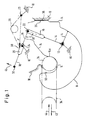
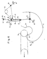
- a coupling body is indicated by hatching at 10.
- a pull hook is pivotally mounted on the coupling body about a pivot axis 12.
- the towing hook is indicated by a contour line and designated 14.
- An elongated hole 16 is made on the draw hook.
- a control lever is designated 18 and designed with an elongated hole 20. This control lever is guided with the elongated hole 20 on an articulated head 24 which is fixedly arranged on the coupling body 10, forming a swivel-slide connection 20, 24.
- a joint head 22 of the control lever 18 and the elongated hole 16 of the pull hook 14 form a swivel slide connection 16, 22.
- leg spring 26 which is pivotally mounted on the coupling body 10 at 28 and is articulated at 30 with the control lever 18.
- a handle 32 is attached to the control lever 18.
- the pull hook 14 is in its coupling position.
- a towing eye 34 is coupled into the towing hook 14.
- the pull hook 14 is secured against rotation in the clockwise direction by a stop 36 which bears against a counter stop 38 of the coupling body.
- the pull hook is secured by the control lever 18 as follows:
- the control lever 18 forms an angle 40 with the elongated hole 16 which is less than 90 degrees. If the pull hook 14 wants to rotate in the counterclockwise direction, the joint head 22 rests against the upper end of the elongated hole 16 and the elongated hole 20 rests with its right end against the stationary joint head 24.
- the angle 40 wants to decrease.
- the towing hook 14 wants to turn clockwise and rests with its stop 36 against the fixed stop 38.
- the towing eye 34 exerts an entry pressure in the direction of the arrow 44 on the flank 14a of the towing hook, ie a moment in a clockwise direction about the pivot axis 12 and that this moment is absorbed by the interaction of the stops 36 and 38. It is further assumed that the intention is to disengage the clutch while the towing eye 34 exerts this entry pressure on the towing hook 14.
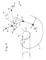
- the control lever 18 is pivoted in the direction of arrow 46.
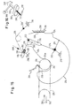
- the state according to FIG. 2 arises. In this state, the pull hook 14 is still in the coupling position.
- the control lever 18 has, however, set itself to a disengagement-ready state and is kept stable in this disengagement-ready state by the leg spring 26; one can imagine this in such a way that the spring force F exerts a clockwise torque on the control lever 18, so that because of the adjustment of the elongated hole 16, the joint head 22 wants to fall down and to the left into the lower end of the elongated hole 16.
- FIG. 12 represents the same state. If this state is reached according to FIG. 2, the operator can take his hand away from the control lever 18 and the control lever remains in the disengagement-ready state according to FIG. 2.
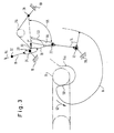
- the pull hook 14 can pivot about the pivot axis 12 in the direction of arrow 52 in the transition from FIG. 2 to FIG. 3.
- the joint head 22 initially maintains its position in the lower end of the elongated hole 16 (FIG. 3).
- the angle 53 enclosed between the spring force F and the control lever 18 maintains its size (of less than 90 degrees), while the angle 55 included between the control lever 18 and the elongated hole 16 is smaller and the force application point of the spring force F is shifted towards the joint head 24 is, so that a force arises in the direction of arrow 54, which tries to push the control lever 18 upwards.
- the falling of the pull hook 14 is supported by gravity.
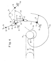
- FIG. 4 shows that the control lever 18 has stepped upward, so that the lower end of the elongated hole 20 bears against the fixed joint head 24.
- control lever can be brought up to the state in FIG. 7 without interruption, and the towing hook 14 moves in one go under the effect of it acting gravity in the state of Figure 7.
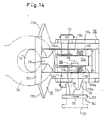
- FIGS. 11 and 14 show in detail the embodiment of the coupling which is only shown schematically in FIGS. 1 to 10. Analog parts are provided with the same reference numerals as in FIG. 1, increased by the number 100.
- the pull hook 114 is supported by a continuous bolt 112 which is supported in the two housing halves 110a of the coupling body 110.
- the pull hook 114 has a pull hook web 114c, in the area of which the elongated hole 116 is arranged. This web 114c engages between two legs 118a of the control lever 118.
- An elongated hole 120 is arranged in each of the two legs 118a.
- a bolt 124a which is supported in the housing halves 110a, engages in each of the two elongated holes 120.
- a coupling mouth 110b can be seen. In the disengaged position, the pull hook 114 rests with a stop surface 115 on a counter stop surface 117 of the coupling body 110.
- a secondary fuse 164 can be seen in FIG.
- This secondary fuse comprises a securing bolt 166 which engages in the elongated hole 116 in the coupling state according to FIG. 11.
- this securing bolt 166 is in direct engagement with the pull hook 114 and also blocks the movement of the swivel-slide connection 116, 122. This has the advantage that even if a break in the area of the control lever 118 should have occurred, the pull hook 114 passes through the securing bolt 166 is still secured.
- the locking bolt 166 is under the action of a compression and torsion spring, not shown, which pushes it into the dashed position according to FIG. 14 and attempts to turn it in the direction of arrow 170.
- the securing bolt 166 is provided with a turning handle 172 and with a holding projection 174. To prepare for disengaging, the handle 172 is pulled into the dash / double-dotted position according to FIG. 14 and rotated counter to the direction of the arrow 170, so that the holding projection 174 engages in a holding depression 176 of the coupling body. Then the securing bolt 166 assumes the dashed / double-dotted position according to FIG.
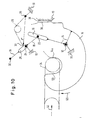
- FIG. 12 shows the coupling according to FIG. 11 in the state according to FIG. 2.
- the spring force F which originates from the leg spring 126, can be seen again.
- forces F1 and F2 result in the direction of the elongated holes 116 and 120, namely a force F1 which acts on the pin 122 of the control lever 118 forming the joint head and acts downwards with the force component F1 'and a force F2, which acts on the control lever 118 and acts upwards.
- the result of the addition of the two forces F1 'and F2 is a resulting force F3.
- the state according to FIG. 12 can be additionally secured by an elastic latching threshold, which is shown in FIG. 12 approximately in the middle of the elongated hole 120 and is designated 180. Due to its position, this latching threshold can also secure the state according to FIG. 1 and also the state according to FIG. 7.
- an elastic latching threshold which is shown in FIG. 12 approximately in the middle of the elongated hole 120 and is designated 180. Due to its position, this latching threshold can also secure the state according to FIG. 1 and also the state according to FIG. 7.
- the towing eye 134 has a favorable lever arm h with respect to the pivot axis 112 when it is pushed onto the towing hook 114, so that the towing hook 114 is reliably pivoted into the coupling position. It should be noted here that the towing eye 134 inevitably assumes the position shown in FIG. 13 by means of guiding means of the coupling body.
- FIG. 15 shows a modification compared to FIG. 1.
- the same parts are designated by reference numerals as in FIG. 1, each increased by the number 200.
- the only difference from the embodiment according to FIG. 1 is that the handle 32 has been omitted. Instead, an out-of-round sliding block 282 engages in the elongated hole 220, which is rotatable about an axis 281 which is stationary with respect to the coupling body 210 and can be displaced along the elongated hole 220.
- This sliding block 282 is firmly connected to a control shaft 283 on which a handle 280 is seated.
Landscapes
- Engineering & Computer Science (AREA)
- Transportation (AREA)
- Mechanical Engineering (AREA)
- Handcart (AREA)
- Body Structure For Vehicles (AREA)
- Mechanical Control Devices (AREA)
Applications Claiming Priority (2)
| Application Number | Priority Date | Filing Date | Title |
|---|---|---|---|
| DE19893910004 DE3910004A1 (de) | 1989-03-28 | 1989-03-28 | Hakenanhaengerkupplung stichwort: hakenkupplung mit stabilisierter auskupplungsbereitschaftsstellung |
| DE3910004 | 1989-03-28 |
Publications (2)
| Publication Number | Publication Date |
|---|---|
| EP0389875A2 true EP0389875A2 (fr) | 1990-10-03 |
| EP0389875A3 EP0389875A3 (fr) | 1992-09-30 |
Family
ID=6377300
Family Applications (1)
| Application Number | Title | Priority Date | Filing Date |
|---|---|---|---|
| EP19900104924 Withdrawn EP0389875A3 (fr) | 1989-03-28 | 1990-03-15 | Crochet d'attelage de remorque avec une position d'attente de décrochage stabilisée |
Country Status (2)
| Country | Link |
|---|---|
| EP (1) | EP0389875A3 (fr) |
| DE (1) | DE3910004A1 (fr) |
Cited By (3)
| Publication number | Priority date | Publication date | Assignee | Title |
|---|---|---|---|---|
| CN109505635A (zh) * | 2017-09-15 | 2019-03-22 | 长治市永华机械有限公司 | 液压支架自卸钩 |
| CN109606039A (zh) * | 2017-10-04 | 2019-04-12 | 福特全球技术公司 | 用于校正车辆的拖挂栓钩与挂车的栓钩连接器之间的失准的栓钩辅助系统 |
| CN117184200A (zh) * | 2023-08-29 | 2023-12-08 | 深圳市海弘装备技术有限公司 | 一种牵引穿经机纱架移动的牵引设备 |
Family Cites Families (4)
| Publication number | Priority date | Publication date | Assignee | Title |
|---|---|---|---|---|
| US2547313A (en) * | 1948-12-07 | 1951-04-03 | John R Gosser | Automatic trailer coupling |
| DE1008123B (de) * | 1956-12-13 | 1957-05-09 | Rockinger Spezial Fab Joh | Anhaengerkupplung mit einem schwenkbar gelagerten Zughaken |
| FR1334550A (fr) * | 1962-06-30 | 1963-08-09 | Goett Ets | Crochet d'accouplement à verrouillage automatique |
| AT310571B (de) * | 1970-12-09 | 1973-10-10 | Autoreparaturwerkstaette Und A | Anhängerkupplung für Kraftfahrzeuge |
-
1989
- 1989-03-28 DE DE19893910004 patent/DE3910004A1/de not_active Ceased
-
1990
- 1990-03-15 EP EP19900104924 patent/EP0389875A3/fr not_active Withdrawn
Cited By (3)
| Publication number | Priority date | Publication date | Assignee | Title |
|---|---|---|---|---|
| CN109505635A (zh) * | 2017-09-15 | 2019-03-22 | 长治市永华机械有限公司 | 液压支架自卸钩 |
| CN109606039A (zh) * | 2017-10-04 | 2019-04-12 | 福特全球技术公司 | 用于校正车辆的拖挂栓钩与挂车的栓钩连接器之间的失准的栓钩辅助系统 |
| CN117184200A (zh) * | 2023-08-29 | 2023-12-08 | 深圳市海弘装备技术有限公司 | 一种牵引穿经机纱架移动的牵引设备 |
Also Published As
| Publication number | Publication date |
|---|---|
| DE3910004A1 (de) | 1990-10-04 |
| EP0389875A3 (fr) | 1992-09-30 |
Similar Documents
| Publication | Publication Date | Title |
|---|---|---|
| EP2343201B1 (fr) | Attelage | |
| EP0146116B1 (fr) | Attelage de remorque à fonctionnement automatique | |
| EP0578073B1 (fr) | Attelage de remorque | |
| EP0389875A2 (fr) | Crochet d'attelage de remorque avec une position d'attente de décrochage stabilisée | |
| DE1027527B (de) | Fahrzeugkupplung, insbesondere fuer Sattelschlepper | |
| DE3016247A1 (de) | Anhaengerkupplung | |
| CH441422A (de) | Automatische Klauenkupplung für Eisenbahnfahrzeuge | |
| DE2008869A1 (de) | Automatische Verbindungsvorrichtung für Betriebsleitungen an Schienenfahrzeugkupplungen | |
| DE3540641C2 (de) | Anhängerkupplung | |
| DE1228941B (de) | Vorrichtung zur Betaetigung der Fernbedienungs-einrichtung einer Fahrzeughaengerkupplung, insbesondere einer Sattelschlepperkupplung | |
| DE2638483C3 (de) | Vorrichtung zur Fernbedienung der Verriegelungseinrichtung einer selbsttätigen Anhangerkupplung | |
| DE2602143C2 (de) | Anhängerkupplung | |
| DE1280064B (de) | Anhaengerkupplung fuer Kraftfahrzeuge | |
| DE3631688C2 (de) | Zuggabel bei Fahrzeugen | |
| DE7832361U1 (de) | Anhängerkupplung | |
| DE102016108897A1 (de) | Verbindungseinrichtung zum Verbinden eines Zugfahrzeugs mit einem Anhänger | |
| DE652627C (de) | Kugelgelenkkupplung fuer Anhaenger von Kraftfahrzeugen | |
| EP1302341B1 (fr) | Attelage de remorque | |
| AT259619B (de) | Schaltvorrichtung für selbsttätige Eisenbahnkupplungen | |
| EP0228627A1 (fr) | Attelage | |
| DE1142111B (de) | Verriegelungseinrichtung fuer eine Anhaengerkupplung | |
| EP0393216A1 (fr) | Crochet d'attelage | |
| DE960697C (de) | Zugmaschine fuer schwere Anhaenger | |
| DE2057376A1 (de) | Anhaengekupplung fuer Trecker mit Dreipunkt-Aufhaengung zum Kuppeln von Halbanhaengern und landwirtschaftlichen Geraeten | |
| DE2442900C2 (de) | Vorrichtung zum Kuppeln eines Fahrzeuges, insbesondere eines landwirtschaftlichen Schleppers mit einem Gerät oder Anhänger |
Legal Events
| Date | Code | Title | Description |
|---|---|---|---|
| PUAI | Public reference made under article 153(3) epc to a published international application that has entered the european phase |
Free format text: ORIGINAL CODE: 0009012 |
|
| AK | Designated contracting states |
Kind code of ref document: A2 Designated state(s): DE FR GB IT SE |
|
| PUAL | Search report despatched |
Free format text: ORIGINAL CODE: 0009013 |
|
| AK | Designated contracting states |
Kind code of ref document: A3 Designated state(s): DE FR GB IT SE |
|
| 17P | Request for examination filed |
Effective date: 19930211 |
|
| 17Q | First examination report despatched |
Effective date: 19940331 |
|
| STAA | Information on the status of an ep patent application or granted ep patent |
Free format text: STATUS: THE APPLICATION IS DEEMED TO BE WITHDRAWN |
|
| 18D | Application deemed to be withdrawn |
Effective date: 19940811 |