EP0389976B1 - Vorrichtung für eine Leistungs-Hochspannungsquelle - Google Patents
Vorrichtung für eine Leistungs-Hochspannungsquelle Download PDFInfo
- Publication number
- EP0389976B1 EP0389976B1 EP90105517A EP90105517A EP0389976B1 EP 0389976 B1 EP0389976 B1 EP 0389976B1 EP 90105517 A EP90105517 A EP 90105517A EP 90105517 A EP90105517 A EP 90105517A EP 0389976 B1 EP0389976 B1 EP 0389976B1
- Authority
- EP
- European Patent Office
- Prior art keywords
- high voltage
- printed circuit
- circuit board
- power source
- electric power
- Prior art date
- Legal status (The legal status is an assumption and is not a legal conclusion. Google has not performed a legal analysis and makes no representation as to the accuracy of the status listed.)
- Expired - Lifetime
Links
Images

Classifications
-
- F—MECHANICAL ENGINEERING; LIGHTING; HEATING; WEAPONS; BLASTING
- F24—HEATING; RANGES; VENTILATING
- F24C—DOMESTIC STOVES OR RANGES ; DETAILS OF DOMESTIC STOVES OR RANGES, OF GENERAL APPLICATION
- F24C7/00—Stoves or ranges heated by electric energy
- F24C7/02—Stoves or ranges heated by electric energy using microwaves
-
- H—ELECTRICITY
- H05—ELECTRIC TECHNIQUES NOT OTHERWISE PROVIDED FOR
- H05K—PRINTED CIRCUITS; CASINGS OR CONSTRUCTIONAL DETAILS OF ELECTRIC APPARATUS; MANUFACTURE OF ASSEMBLAGES OF ELECTRICAL COMPONENTS
- H05K1/00—Printed circuits
- H05K1/02—Details
- H05K1/0213—Electrical arrangements not otherwise provided for
- H05K1/0254—High voltage adaptations; Electrical insulation details; Overvoltage or electrostatic discharge protection ; Arrangements for regulating voltages or for using plural voltages
- H05K1/0256—Electrical insulation details, e.g. around high voltage areas
-
- H—ELECTRICITY
- H05—ELECTRIC TECHNIQUES NOT OTHERWISE PROVIDED FOR
- H05K—PRINTED CIRCUITS; CASINGS OR CONSTRUCTIONAL DETAILS OF ELECTRIC APPARATUS; MANUFACTURE OF ASSEMBLAGES OF ELECTRICAL COMPONENTS
- H05K1/00—Printed circuits
- H05K1/02—Details
-
- H—ELECTRICITY
- H05—ELECTRIC TECHNIQUES NOT OTHERWISE PROVIDED FOR
- H05K—PRINTED CIRCUITS; CASINGS OR CONSTRUCTIONAL DETAILS OF ELECTRIC APPARATUS; MANUFACTURE OF ASSEMBLAGES OF ELECTRICAL COMPONENTS
- H05K1/00—Printed circuits
- H05K1/02—Details
- H05K1/0213—Electrical arrangements not otherwise provided for
- H05K1/0254—High voltage adaptations; Electrical insulation details; Overvoltage or electrostatic discharge protection ; Arrangements for regulating voltages or for using plural voltages
- H05K1/0262—Arrangements for regulating voltages or for using plural voltages
-
- H—ELECTRICITY
- H05—ELECTRIC TECHNIQUES NOT OTHERWISE PROVIDED FOR
- H05K—PRINTED CIRCUITS; CASINGS OR CONSTRUCTIONAL DETAILS OF ELECTRIC APPARATUS; MANUFACTURE OF ASSEMBLAGES OF ELECTRICAL COMPONENTS
- H05K1/00—Printed circuits
- H05K1/02—Details
- H05K1/0213—Electrical arrangements not otherwise provided for
- H05K1/0216—Reduction of cross-talk, noise or electromagnetic interference
- H05K1/0218—Reduction of cross-talk, noise or electromagnetic interference by printed shielding conductors, ground planes or power plane
- H05K1/0219—Printed shielding conductors for shielding around or between signal conductors, e.g. coplanar or coaxial printed shielding conductors
-
- H—ELECTRICITY
- H05—ELECTRIC TECHNIQUES NOT OTHERWISE PROVIDED FOR
- H05K—PRINTED CIRCUITS; CASINGS OR CONSTRUCTIONAL DETAILS OF ELECTRIC APPARATUS; MANUFACTURE OF ASSEMBLAGES OF ELECTRICAL COMPONENTS
- H05K2201/00—Indexing scheme relating to printed circuits covered by H05K1/00
- H05K2201/09—Shape and layout
- H05K2201/09209—Shape and layout details of conductors
- H05K2201/09654—Shape and layout details of conductors covering at least two types of conductors provided for in H05K2201/09218 - H05K2201/095
- H05K2201/0969—Apertured conductors
-
- H—ELECTRICITY
- H05—ELECTRIC TECHNIQUES NOT OTHERWISE PROVIDED FOR
- H05K—PRINTED CIRCUITS; CASINGS OR CONSTRUCTIONAL DETAILS OF ELECTRIC APPARATUS; MANUFACTURE OF ASSEMBLAGES OF ELECTRICAL COMPONENTS
- H05K2201/00—Indexing scheme relating to printed circuits covered by H05K1/00
- H05K2201/09—Shape and layout
- H05K2201/09209—Shape and layout details of conductors
- H05K2201/09654—Shape and layout details of conductors covering at least two types of conductors provided for in H05K2201/09218 - H05K2201/095
- H05K2201/09781—Dummy conductors, i.e. not used for normal transport of current; Dummy electrodes of components
-
- H—ELECTRICITY
- H05—ELECTRIC TECHNIQUES NOT OTHERWISE PROVIDED FOR
- H05K—PRINTED CIRCUITS; CASINGS OR CONSTRUCTIONAL DETAILS OF ELECTRIC APPARATUS; MANUFACTURE OF ASSEMBLAGES OF ELECTRICAL COMPONENTS
- H05K2201/00—Indexing scheme relating to printed circuits covered by H05K1/00
- H05K2201/09—Shape and layout
- H05K2201/09818—Shape or layout details not covered by a single group of H05K2201/09009 - H05K2201/09809
- H05K2201/09972—Partitioned, e.g. portions of a PCB dedicated to different functions; Boundary lines therefore; Portions of a PCB being processed separately or differently
Definitions
- the present invention relates to high voltage power source devices for use in, for example, an electronic oven comprising a semiconductor switching element for converting an electric power available from a commercial power outlet into a high frequency electric power, and a high voltage power source device for use in the electronic oven for boosting such high frequency electric power and for supplying it to a magnetron.
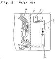
- the prior art high voltage power source device shown in Fig. 8 comprises a printed circuit board 1 having only one of the opposite surfaces formed with a patterned grounding conductor 2 to avoid any possible leakage of electric power between a high voltage circuit and a low voltage circuit.
- the patterned grounding conductor 2 is formed only on one surface of the printed circuit board 1, the patterned grounding conductor 2 does not work on the leakage of electric power occurring on the opposite surface of the same printed circuit board 1.
- this electric power converting device is used in an electronic oven, and since the printed circuit board 1 may often been contaminated by vapor originating from food material being heated within the oven and/or moisture component and dust afloat in a kitchen, there is a relatively high possibility that the high voltage circuit and the low voltage circuit are electrically shortcircuitted through deposits of those contaminants.
- the patterned grounding conductor 2 is formed on one surface of the printed circuit board 1, a deposit of contaminants such as, for example, water droplets and/or dust tends to constitute a cause for an unwanted leakage of electric power from the opposite surface to the surface of the printed circuit board 1 on which the grounding conductor 2 is formed and, therefore, the formation of the patterned grounding conductor 2 only on such surface of the printed circuit board 1 is ineffective to eliminate the occurrence of a leakage of electric power between the opposite surfaces of the printed circuit board 1.
- the present invention has been devised with a view to substantially eliminating the above discussed problem and has for its essential object to eliminate any possible leakage of a high voltage in the high voltage circuit to the patterned grounding conductor in the event that contaminants such as, for example, water droplets and/or dust deposit on the surface of the printed circuit board opposite to the surface thereof where the patterned grounding conductor is formed.
- a high voltage power source device which comprises a printed circuit board having a high and a low voltage circuit formed respectively on separate portions of the printed circuit board.
- the high voltage power source device also comprises a patterned grounding conductor formed in the printed circuit board at the boundary between the separate portions.
- the printed circuit board has a plurality of openings such as, for example, slits or apertures, defined in alignment with the patterned grounding conductor so as to extend completely through the thickness of the printed circuit board.
- the high voltage power source device In the high voltage power source device according to the first preferred embodiment of the present invention, even when contaminants such as, for example, water droplets and/or dust deposit on the second surface of the printed circuit board which is opposite to the first surface thereof where the patterned grounding conductor is formed, a voltage in the high voltage circuit can be coupled with the patterned grounding conductor through the openings. Also, the presence of the openings in the printed circuit board in alignment with the patterned grounding conductor increases the leakage distance and, therefore, the voltage breakdown characteristic of the printed circuit board can advantageously be improved.
- a high voltage power source device comprises a printed circuit board having first and second surfaces opposite to each other and also having a high and a low voltage circuit formed respectively on separate portions of the first surface of the printed circuit board.
- the high voltage power source device also comprises a patterned grounding conductor formed on the first surface of the printed circuit board at the boundary between the separate portions of the surface thereof, and a plurality of generally elongated conductive pieces such as, for example, metal wires or metal foils, disposed on the second surface of the printed circuit board, each of said conductive pieces having its opposite ends connected with the patterned grounding conductor on the first surface of the printed circuit board.
- the high voltage power source device even when contaminants such as, for example, water droplets and/or dust deposit on the second surface of the printed circuit board which is opposite to the first surface thereof where the patterned grounding conductor is formed, a voltage in the high voltage circuit can be grounded through the conductive pieces. Also, even when the patterned grounding conductor breaks as a result of cracking in the printed circuit board, the conductive pieces are effective to ensure a firm grounding of the voltage in the high voltage circuit therethrough.
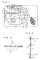
- a high voltage power source device shown therein comprises a high voltage circuit including a high voltage capacitor connected with a high voltage terminal 6b of a secondary winding of a high voltage transformer through a patterned high voltage conductor 3, a high voltage diode 5 and high voltage heater terminals 6c, and a low voltage circuit including a semiconductor switching element 8 connected with terminals 7a and 7b of a primary winding of the high voltage transformer through patterned low voltage conductors 11, a smoothing capacitor 9, a resonating capacitor 10 and a control circuit 12.
- a patterned grounding conductor 2 is formed.
- an output from the high voltage terminal 6b of the secondary winding of the high voltage transformer is provided in the form of a half-wave step-up voltage of about 4,000 volts which is in turn supplied to a magnetron 15 shown in Fig. 7.
- the magnetron 15 is grounded through a housing of an electronic oven, and the grounding conductor 2 is connected at a grounding terminal 2a with the housing of the electronic oven by means of a screw member or any other suitable fastening member and at the opposite end with the low voltage terminal 6a of the secondary winding of the high voltage transformer, thereby completing a closed loop on the side of the secondary winding of the transformer.
- the low voltage circuit is operable to rectify an electric current available from a commercial power outlet to provide a high frequency current. Therefore, the electric potential relative to the earth is not so high since one of the paired commercial power lines is connected to the earth. and is, for example, within the range of about 100 to 200 volts and, therefore, no voltage breakdown will substantially occur.
- a printed circuit board 1 having first and second surfaces opposite to each other is contaminated with water droplets and/or dust depositing on the first surface thereof where the grounding conductor 2 is formed and/or is wetted, the breakdown voltage of each of the high voltage circuit and the low voltage circuit will be lowered.
- the grounding conductor 2 is formed at the boundary between the high and low voltage circuits as hereinbefore described, a voltage flowing in the high voltage circuit can be grounded through the grounding conductor 2 and will not leak into the low voltage circuit and particularly into portions of the patterned low voltage conductors 11 adjacent the semiconductor switching element 8.
- the voltage flowing in the high voltage circuit can be grounded through the grounding conductor 2 by means of grounding slits 2b so defined in the printed circuit board 1 as to extend through the grounding conductor 2 and then through the thickness of the printed circuit board 1. Absent the slits 2b such as in the prior art device discussed with reference to Fig. 8, the voltage flowing in the high voltage circuit will be discharged to and, hence, leak into the low voltage circuit to such an extent as to eventually result in a shortcircuitting which is a hazardous condition.
- slits or any other openings such as, for example, holes, results in an increase of the edge-to-edge distance or leakage distance which in turn brings about an increase of the breakdown voltage, thereby ensuring an improved safety factor.
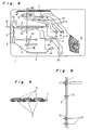
- the grounding slits 2b employed in the foregoing preferred embodiment of the present invention are substituted by metal wiring pieces 2c.
- These metal wiring pieces 2c are disposed on the second surface of the printed circuit board so as to extend along the grounding conductor 2, each of said metal wiring pieces 2c having its opposite ends extending through the printed circuit board 1 and connected with the grounding conductor 2.
- the potential of the grounding conductor 2 can be kept at a ground potential since the metal wiring pieces 2c serve to connect separated areas of the grounding conductor 2, thereby eliminating the occurrence of any possible leakage of electric power.
- Fig. 7 illustrates a high voltage power source device utilizable in the practice of any one of the foregoing preferred embodiments of the present invention.
- one of the paired commercial power lines leading from the commercial electric power source 14 is connected to the ground, and an electric power available from this power source 14 is rectified by a diode bridge network 13 and smoothed by the smoothing capacitor 9.
- An L-C resonant oscillation is achieved by a resonating capacitor 10 and an inductance of a primary winding 7 of the high voltage transformer, and an electric power resulting therefrom is controlled by the semiconductor switching element 8.
- a circuit from the power source 14 to the primary winding 7 of the high voltage transformer constitutes the low voltage circuit.
- the high voltage circuit is constituted by a circuit from the secondary winding 6 of the high voltage transformer to the magnetron 15, and one end of the high voltage circuit, that is, the low voltage terminal 6a of the secondary winding of the high voltage transformer is connected with the housing or any other framework of the electronic oven for grounding. This applies even where metal foils are employed in place of the metal wiring pieces 2c. while in general the housing or framework of the electronic oven has to be grounded to secure a safety factor, it is often observed that the housing or framework of the electronic oven is not connected to the ground.
- any one of the first and second embodiment of the present invention which has been shown in and described with reference to Figs. 1 to 3 and Figs.
- 4 to 6 is effective to provide the high voltage power source device which is substantially free from any possible leakage of electric power which would occur not only on one surface of the printed circuit board, but also on the opposite surfaces thereof, thereby to avoid a charge build-up in the housing or framework of the electronic oven while safeguarding the user from any possible electric shock.
- the high voltage power source device can bring about the following advantages.
- the high voltage power source device can bring about the following advantages.
Landscapes
- Engineering & Computer Science (AREA)
- Microelectronics & Electronic Packaging (AREA)
- Chemical & Material Sciences (AREA)
- Combustion & Propulsion (AREA)
- Mechanical Engineering (AREA)
- General Engineering & Computer Science (AREA)
- Structure Of Printed Boards (AREA)
- Inverter Devices (AREA)
- Control Of High-Frequency Heating Circuits (AREA)
Claims (4)
- Hochspannungserzeugungsvorrichtung mit einer gedruckten Platine (1) mit einem Niederspannungsschaltkreis (7 bis 12) und einem Hochspannungsschaltkreis (3 bis 6), welche jeweils auf separaten Bereichen der gedruckten Platine ausgebildet sind; und mit einem strukturierten Masseleiter (2), der an der Grenze zwischen den separaten Bereichen in der gedruckten Platine ausgebildet ist, wobei die gedruckte Platine mehrere Öffnungen (2b) besitzt, die vollständig durch die Dicke der Platine in Ausrichtung zum strukturierten Masseleiter verlaufen.
- Hochspannungserzeugungsvorrichtung nach Anspruch 1, mit einer elektrischen Spannungsquelle;
einer Wechselrichterschaltung mit einem Halbleiterschaltelement und einem Kondensator zum Umwandeln einer elektrischen Spannung von der elektrischen Spannungsquelle in eine hochfrequente elektrische Spannung, wobei die Wechselrichterschaltung den Niederspannungsschaltkreis bildet;
einem Magnetron, der eine Hochspannung benötigt;
einem Hochspannungstransformator zum Umwandeln der hochfrequenten elektrischen Spannung in eine Hochspannung und zur Versorgung des Magnetrons mit Hochspannung;
wobei die gedruckte Platine ein darauf ausgebildetes elektrisches Verdrahtungssystem zum Anschluß und zur Halterung der Wechselrichterschaltung darauf und den Hochspannungsschaltkreis für die vom Hochspannungstransformator erhöhte Spannung besitzt. - Hochspannungserzeugungsvorrichtung mit einer gedruckten Platine (1) mit einander gegenüberliegenden ersten und zweiten Oberflächen und ebenfalls mit einem Niederspannungsschaltkreis (7 bis 12) und einem Hochspannungsschaltkreis (3 bis 6), welche jeweils auf separaten Bereichen der ersten Oberfläche ausgebildet sind; einem strukturierten Masseleiter (2), der auf der ersten Oberfläche der gedruckten Platine an der Grenze zwischen den separaten Bereichen ausgebildet ist; und mehreren im wesentlichen länglichen elektrisch leitenden Teilen (2c), die auf der zweiten Oberfläche der gedruckten Platine angeordnet sind, von denen jedes elektrisch leitende Teil mit seinen entgegengesetzten Enden am strukturierten Masseleiter angeschlossen ist.
- Hochspannungserzeugungsvorrichtung nach Anspruch 3, mit einer elektrischen Spannungsquelle;
einer Wechselrichterschaltung mit einem Halbleiterschaltelement und einem Kondensator zum Umwandeln einer elektrischen Spannung von der elektrischen Spannungsquelle in eine hochfrequente elektrische Spannung, wobei die Wechselrichterschaltung den Niederspannungsschaltkreis bildet;
einem Magnetron, das eine Hochspannung benötigt;
einem Hochspannungstransformator zum Umwandeln der hochfrequenten elektrischen Spannung in eine Hochspannung und zum Versorgen des Magnetrons mit der Hochspannung;
wobei die gedruckte Platine ein darauf ausgebildetes elektrisches Verdrahtungssystem zum Anschluß und zur Halterung der Wechselrichterschaltung und den Hochspannungsschaltkreis für die vom Hochspannungstransformator erhöhte Spannung besitzt.
Applications Claiming Priority (2)
| Application Number | Priority Date | Filing Date | Title |
|---|---|---|---|
| JP1075314A JP2523860B2 (ja) | 1989-03-27 | 1989-03-27 | 電力変換装置 |
| JP75314/89 | 1989-03-27 |
Publications (3)
| Publication Number | Publication Date |
|---|---|
| EP0389976A2 EP0389976A2 (de) | 1990-10-03 |
| EP0389976A3 EP0389976A3 (de) | 1992-08-26 |
| EP0389976B1 true EP0389976B1 (de) | 1994-07-06 |
Family
ID=13572672
Family Applications (1)
| Application Number | Title | Priority Date | Filing Date |
|---|---|---|---|
| EP90105517A Expired - Lifetime EP0389976B1 (de) | 1989-03-27 | 1990-03-23 | Vorrichtung für eine Leistungs-Hochspannungsquelle |
Country Status (6)
| Country | Link |
|---|---|
| US (1) | US4999762A (de) |
| EP (1) | EP0389976B1 (de) |
| JP (1) | JP2523860B2 (de) |
| KR (1) | KR930005351B1 (de) |
| CA (1) | CA2012790C (de) |
| DE (1) | DE69010361T2 (de) |
Families Citing this family (12)
| Publication number | Priority date | Publication date | Assignee | Title |
|---|---|---|---|---|
| US5598057A (en) * | 1995-03-13 | 1997-01-28 | Texas Instruments Incorporated | Reduction of the probability of interlevel oxide failures by minimization of lead overlap area through bus width reduction |
| JPH10136696A (ja) * | 1996-10-29 | 1998-05-22 | Mitsubishi Electric Corp | 車両用交流発電機の制御装置 |
| US5892303A (en) * | 1997-03-28 | 1999-04-06 | Xerox Corporation | Compact design for combination of an electrical circuit with a segmented electrode development roll |
| JP3857278B2 (ja) * | 2004-04-06 | 2006-12-13 | Smk株式会社 | タッチパネル入力装置 |
| JP5039356B2 (ja) * | 2006-10-13 | 2012-10-03 | 三菱重工業株式会社 | 制御基板および電動圧縮機の制御装置ならびに電動圧縮機 |
| JP5422271B2 (ja) * | 2009-06-25 | 2014-02-19 | 株式会社東芝 | 電子レンジのトランス搭載基板装置 |
| JP5186029B2 (ja) * | 2011-08-15 | 2013-04-17 | 三菱重工業株式会社 | 制御基板及び電動圧縮機の制御装置 |
| CN103312128A (zh) * | 2013-06-24 | 2013-09-18 | 上海广电电气(集团)股份有限公司 | 带有室外电缆通道的高压变频器 |
| CN104092222B (zh) * | 2014-06-30 | 2016-04-27 | 深圳市英威腾电气股份有限公司 | 一种功率单元及高压电力变换设备 |
| JP7052324B2 (ja) | 2017-11-30 | 2022-04-12 | 株式会社リコー | 基板及び電源装置 |
| CN109951948B (zh) * | 2019-03-21 | 2024-07-05 | 厦门大学 | 一种板级安规绝缘方案 |
| KR20240139403A (ko) * | 2023-03-14 | 2024-09-23 | 한온시스템 주식회사 | 전동압축기 |
Family Cites Families (7)
| Publication number | Priority date | Publication date | Assignee | Title |
|---|---|---|---|---|
| JPS52137671A (en) * | 1976-05-12 | 1977-11-17 | Sanyo Electric Co | Device for preventing circuit parts from breaking |
| IT1151379B (it) * | 1982-03-30 | 1986-12-17 | Fiar Spa | Dispositivo moltiplicatore di tensione per apparecchi ad alta tensione,in particolare per applicazioni spaziali |
| JPS59201637A (ja) * | 1983-04-28 | 1984-11-15 | キヤノン株式会社 | 電源装置 |
| US4772999A (en) * | 1986-12-16 | 1988-09-20 | Merlin Gerin | Static converter, especially for an uninterruptible electrical power supply system |
| JPS6472584A (en) * | 1987-09-11 | 1989-03-17 | Sharp Kk | Printed wiring board |
| IT211826Z2 (it) * | 1987-09-15 | 1989-05-25 | Microset Srl | Scheda madre a circuito stampato per bus di microprocessori. |
| US4868462A (en) * | 1988-01-27 | 1989-09-19 | Gendex Corporation | High voltage transformer for high frequency medical X-ray generator |
-
1989
- 1989-03-27 JP JP1075314A patent/JP2523860B2/ja not_active Expired - Lifetime
-
1990
- 1990-03-22 CA CA002012790A patent/CA2012790C/en not_active Expired - Lifetime
- 1990-03-23 DE DE69010361T patent/DE69010361T2/de not_active Expired - Lifetime
- 1990-03-23 EP EP90105517A patent/EP0389976B1/de not_active Expired - Lifetime
- 1990-03-27 KR KR1019900004132A patent/KR930005351B1/ko not_active Expired - Fee Related
- 1990-03-27 US US07/500,254 patent/US4999762A/en not_active Expired - Lifetime
Also Published As
| Publication number | Publication date |
|---|---|
| JPH02252286A (ja) | 1990-10-11 |
| EP0389976A2 (de) | 1990-10-03 |
| KR930005351B1 (ko) | 1993-06-17 |
| DE69010361D1 (de) | 1994-08-11 |
| JP2523860B2 (ja) | 1996-08-14 |
| KR900014821A (ko) | 1990-10-25 |
| CA2012790A1 (en) | 1990-09-27 |
| CA2012790C (en) | 1994-09-27 |
| DE69010361T2 (de) | 1995-02-23 |
| US4999762A (en) | 1991-03-12 |
| EP0389976A3 (de) | 1992-08-26 |
Similar Documents
| Publication | Publication Date | Title |
|---|---|---|
| EP0389976B1 (de) | Vorrichtung für eine Leistungs-Hochspannungsquelle | |
| AU604197B2 (en) | High-frequency heating apparatus using frequency-converter- type power supply | |
| EP0597661B1 (de) | Verbesserungen in einem elektrischen Gerät | |
| US4320307A (en) | Arrangement for interference suppression of electromagnetic circuits | |
| US4583056A (en) | Apparatus having printed circuit pattern for suppressing radio interference | |
| JP3168929B2 (ja) | 高周波加熱装置 | |
| JP2585213B2 (ja) | 調理器 | |
| US5751568A (en) | Power supply apparatus for arc-utilizing equipment | |
| JP2517089B2 (ja) | 電力変換装置 | |
| JPH03218612A (ja) | 電力変換装置 | |
| JP3458736B2 (ja) | マグネトロン駆動用電源 | |
| JP2512100B2 (ja) | 高周波加熱装置 | |
| KR200146188Y1 (ko) | 전자 렌지의 고압 트랜스 보호용 퓨즈 장착 구조 | |
| KR200143526Y1 (ko) | 전자렌지의 고전압트랜스보호용 휴즈장착구조 | |
| KR900009190Y1 (ko) | 조리기 | |
| KR0139296Y1 (ko) | 전자 렌지의 고압 트랜스 보호용 퓨즈 장착 구조 | |
| JP2541723Y2 (ja) | 高周波加熱装置用インバータ電源 | |
| KR200146187Y1 (ko) | 전자 렌지의 고압 트랜스 보호용 퓨즈 장착 구조 | |
| JPH03148893A (ja) | プリント配線基板 | |
| KR200143524Y1 (ko) | 전자 렌지의 고압 트랜스 보호용 퓨즈 장착 구조 | |
| KR200211127Y1 (ko) | 전파배압회로 | |
| JPH07226166A (ja) | 電源一体型マグネトロン装置 | |
| JPH0828242B2 (ja) | 接続端子 | |
| JPH0642397Y2 (ja) | 放電灯用インバータ装置のシールド構造 | |
| JPH0541275A (ja) | 誘導加熱調理器 |
Legal Events
| Date | Code | Title | Description |
|---|---|---|---|
| PUAI | Public reference made under article 153(3) epc to a published international application that has entered the european phase |
Free format text: ORIGINAL CODE: 0009012 |
|
| 17P | Request for examination filed |
Effective date: 19900323 |
|
| AK | Designated contracting states |
Kind code of ref document: A2 Designated state(s): DE FR GB IT |
|
| PUAL | Search report despatched |
Free format text: ORIGINAL CODE: 0009013 |
|
| AK | Designated contracting states |
Kind code of ref document: A3 Designated state(s): DE FR GB IT |
|
| 17Q | First examination report despatched |
Effective date: 19930907 |
|
| GRAA | (expected) grant |
Free format text: ORIGINAL CODE: 0009210 |
|
| AK | Designated contracting states |
Kind code of ref document: B1 Designated state(s): DE FR GB IT |
|
| ITF | It: translation for a ep patent filed | ||
| REF | Corresponds to: |
Ref document number: 69010361 Country of ref document: DE Date of ref document: 19940811 |
|
| ET | Fr: translation filed | ||
| PLBE | No opposition filed within time limit |
Free format text: ORIGINAL CODE: 0009261 |
|
| STAA | Information on the status of an ep patent application or granted ep patent |
Free format text: STATUS: NO OPPOSITION FILED WITHIN TIME LIMIT |
|
| 26N | No opposition filed | ||
| REG | Reference to a national code |
Ref country code: GB Ref legal event code: IF02 |
|
| PGFP | Annual fee paid to national office [announced via postgrant information from national office to epo] |
Ref country code: GB Payment date: 20090318 Year of fee payment: 20 |
|
| PGFP | Annual fee paid to national office [announced via postgrant information from national office to epo] |
Ref country code: DE Payment date: 20090319 Year of fee payment: 20 Ref country code: IT Payment date: 20090320 Year of fee payment: 20 |
|
| PGFP | Annual fee paid to national office [announced via postgrant information from national office to epo] |
Ref country code: FR Payment date: 20090316 Year of fee payment: 20 |
|
| REG | Reference to a national code |
Ref country code: GB Ref legal event code: PE20 Expiry date: 20100322 |
|
| PG25 | Lapsed in a contracting state [announced via postgrant information from national office to epo] |
Ref country code: GB Free format text: LAPSE BECAUSE OF EXPIRATION OF PROTECTION Effective date: 20100322 |
|
| PG25 | Lapsed in a contracting state [announced via postgrant information from national office to epo] |
Ref country code: DE Free format text: LAPSE BECAUSE OF EXPIRATION OF PROTECTION Effective date: 20100323 |