EP0390050A2 - Méthode et appareil pour la détection de mouvement et la poursuite - Google Patents
Méthode et appareil pour la détection de mouvement et la poursuite Download PDFInfo
- Publication number
- EP0390050A2 EP0390050A2 EP90105761A EP90105761A EP0390050A2 EP 0390050 A2 EP0390050 A2 EP 0390050A2 EP 90105761 A EP90105761 A EP 90105761A EP 90105761 A EP90105761 A EP 90105761A EP 0390050 A2 EP0390050 A2 EP 0390050A2
- Authority
- EP
- European Patent Office
- Prior art keywords
- expansion
- focus
- images
- qualitative
- hypotheses
- Prior art date
- Legal status (The legal status is an assumption and is not a legal conclusion. Google has not performed a legal analysis and makes no representation as to the accuracy of the status listed.)
- Withdrawn
Links
Images











Classifications
-
- G—PHYSICS
- G06—COMPUTING OR CALCULATING; COUNTING
- G06V—IMAGE OR VIDEO RECOGNITION OR UNDERSTANDING
- G06V20/00—Scenes; Scene-specific elements
- G06V20/50—Context or environment of the image
- G06V20/56—Context or environment of the image exterior to a vehicle by using sensors mounted on the vehicle
-
- G—PHYSICS
- G06—COMPUTING OR CALCULATING; COUNTING
- G06T—IMAGE DATA PROCESSING OR GENERATION, IN GENERAL
- G06T7/00—Image analysis
- G06T7/50—Depth or shape recovery
- G06T7/55—Depth or shape recovery from multiple images
- G06T7/579—Depth or shape recovery from multiple images from motion
-
- G—PHYSICS
- G06—COMPUTING OR CALCULATING; COUNTING
- G06T—IMAGE DATA PROCESSING OR GENERATION, IN GENERAL
- G06T2207/00—Indexing scheme for image analysis or image enhancement
- G06T2207/10—Image acquisition modality
- G06T2207/10016—Video; Image sequence
Definitions
- the present invention pertains to a method and apparatus for the detection and tracking of moving objects from a moving platform according to the preamble of the independent claims.
- Moving objects must be detected and isolated from the stationary environment, their current motions must be estimated to track them, and expectations about their future behavior must be created. Since the camera itself is moving, the stationary part of the scene cannot be assumed to be registered in subsequent images, as in the case of a stationary sensor. Simple frame-differencing or feature-matching techniques to detect and isolate moving objects do not work in this case because image changes, due to sensor motion, tend to generate too many false alarms in cluttered scenes.
- More sophisticated image-based techniques which apply 2-D transformations (warping) to the image to compensate for background motion, work well only when objects are moving in front of a relatively flat background, such as in some air-to-ground applications.
- 2-D transformations warping
- the present invention for motion detection consists of three attainments: 1) estimating the robot's egomotion; 2) reconstructing the 3-D scene structure; and 3) evaluating the motion of individual objects from a sequence of monocular images.
- a two-stage process used in the invention begins with given sets of displacement vectors between distinct image features in successive frames. The availability of reliable displacement vectors is vital. Although manual point tracking is used for the examples given below, automatic feature selection and tracking is possible.
- the robot's egomotion is computed in terms of rotations and the direction of translation.
- a "fuzzy" focus of expansion (FOE) concept is used, which defines an image region rather than a single point. All of the numerical effort is packed into the computation of the "focus of expansion” (FOE), a low-level process which is performed entirely in 2-D.
- the FOE concept has been extended to cope with the problems of noise and errors in the original displacement vectors. Instead of a single FOE, one determines a connected region of possible FOE-locations, called the fuzzy FOE, whose shape is directly related to the "goodness" of the displacement field.
- a 3-D scene model is constructed by analyzing the movements and positions of image features relative to each other and relative to the fuzzy FOE.
- the heart of this invention demonstrates how a fuzzy FOE is used to draw powerful conclusions about motion and the 3-D scene structure. From these clues, one can construct and maintain an internal 3-D representation, termed the qualitative scene model (QSM), in a generate-and-test cycle over extended image sequences.
- QSM quantitative scene model
- the QSM can also serve as a platform for other visual processes such as occlusion analysis, perceptual grouping, and object recognition.
- the 3-D motion is detected in two ways: to begin, some forms of motion are concluded directly from the 2-D displacement vectors without any knowledge about the underlying 3-D structure. Next, motion is detected by discovering inconsistencies between the current state of the internal 3-D scene model and the changes actually observed in the image. Detected objects are tracked from frame to frame.
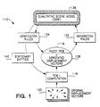
- the overall structure of the interpretation process begins with original displacement vectors. From the original displacement vectors (obtained by matching corresponding features), the fuzzy FOE and the derotated displacement field are computed.
- the qualitative scene model (QSM) is built in a hypothesize-and-test cycle by two sets of rules. Generation rules search for significant image events and place immediate conclusions (hypotheses) in the model. Verification rules check existing hypotheses if they are consistent with the changes occurring in the image. A set of environmental entities that are believed to be stationary is supplied by the QSM to be used by the FOE-computation.
- the QSM can be considered as the "mind" of the motion detection and tracking system.
- the QSM is a 3-D camera-centered representation of the scene which describes the observed environment by using a set of simple qualitative relationships.
- the set of entities in the QSM is conceptually split into two parts -- the stationary world and a set of independently moving objects. Construction of the QSM over time is accomplished by a reasoning process which draws conclusions from significant configurations and changes in the image. As the vehicle travels through the environment, the QSM is continuously updated and revised by adding or deleting hypotheses.
- the state of the QSM is not a single interpretation but a set of interpretations which are all pursued simultaneously. This state provides a very flexible mechanism for handling the inherent ambiguities encountered in image understanding.
- Each interpretation is a collection of hypotheses called partial interpretations which cover overlapping subjects of the entities in the model.
- FIG. 1 illustrates the heart of the invention, that is, structure 10 of the scene interpretation process.
- An important computation 116 of the present invention 110 is the focus of expansion (FOE), i.e., the image location from which all points seem to diverge radially under pure camera translation in the forward direction.
- FOE focus of expansion
- locating the FOE accurately is generally impossible under noisy conditions.
- this concept has been extended by computing a patch of possible FOE locations, called the fuzzy FOE 118, instead of a single point.
- the present invention has two main components. Given a set of point (token) correspondences for each pair of frames, one first computes the fuzzy FOE 118 and removes the effects of camera rotation. In the second step, one uses the 2-D locations and motion of features relative to each other and relative to the fuzzy FOE 118 to reason about the 3-D scene structure as well as 3-D motion of moving objects. These results are used to incrementally construct a model of the environment, which includes the information about the static scene structure and the moving objects therein. This reasoning process and the scene model are characterized by two key features -- the emphasis on qualitative techniques and the ability to pursue multiple scene interpretations simultaneously.
- the overall process of constructing the scene interpretations consists of three main steps.
- the second step one uses the original displacement field 120 to compute the fuzzy FOE 118, i.e., the vehicle's approximate direction of heading and the amount of rotation in space. Most of the necessary quantitative computations are performed in this 2-D step which is described below.
- the third step (2-D change analysis) constructs the 3-D qualitative scene model by analyzing the movements of individual features with respect to the fuzzy FOE location.
- a camera-centered coordinate system is utilized as illustrated in Figure 2.
- the origin O of the coordinate system is located at the lens center 112 of camera 122.
- the focal length f is the distance between the lens center 112 and the image plane 114.
- a 3-D point (X Y Z) is mapped onto the 2-D image location (x y).
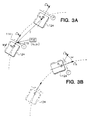
- FIGs 3a and 3b An interpretation of the focus of expansion (FOE) is illustrated in Figures 3a and 3b.
- Vehicle motion between its initial position (where image I is observed) and its final position (image I ′,) is modeled as two separate steps.
- the vehicle translates by a 3-D vector T from position P 0 to position P 1 without changing its orientation ⁇ 0 in Figure 3a.
- the intermediate image I * would be seen.
- the vehicle rotates by changing its orientation from ⁇ 0 to ⁇ 1.
- Now image I ′, is observed.
- the FOE is found where the vector T intersects the image plane I (and also I *).
- the FOE can be located for the pair of images I and I *.
- the displacement vectors are extended as straight lines to measure the spread of their intersections.
- the resulting error functions are noise-sensitive and not well behaved for varying values of ⁇ and ⁇ , i.e., they require expensive global search.
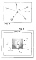
- Figure 4 shows how the deviation from a radial expansion pattern is measured.
- the deviation is defined as the sum of the perpendicular distances ⁇ d i .
- the sum of the perpendicular distances d i between radial rays and the end points of the displacement vectors 120 is a simple and useful measure ( Figure 4).
- the optimal rotation angles for a particular FOE 115 i.e., those that would minimize this deviation, and the remaining error, can be found analytically.
- This remaining error is used as the criterion to evaluate a hypothetical FOE.
- the resulting error function is smooth and monotonic within a large area around the actual FOE. This means that even from a poor initial guess the global optimum can be found by local search methods, such as steepest descent.
- fuzzy FOE The concept of the FOE has been extended to specify not a single image location but a connected region, termed the fuzzy FOE, that reflects the shape of the error distribution.
- a flat error function is reflected by a large fuzzy FOE, i.e., little accuracy in the location of the FOE, whereas a small region indicates a distinct local optimum for the FOE.
- the following algorithm computes the fuzzy FOE by first looking for the bottom of the error function and then accumulating surrounding FOE-locations (see Figure 5). Fuzzy_FOE ( I , I ′): (Compute the fuzzy FOE for a given pair of images I and I ′).
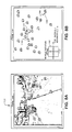
- Figure 5 displays the results of applying this algorithm to a simulated sparse displacement field.
- the shape of the error function 118 around the actual FOE 115 is plotted with circles 126 of size proportional to the error.
- the blank area 128 in the center of Figure 5, marks the resulting fuzzy FOE for the simulated displacement field.
- Vehicle 124 of Figure 3a is translating forward and rotating to the right by 2°.
- the small square in the center is the location of the actual FOE 115 ( Figure 5). Notice the elongated shape of the FOE region 128 which is due to the particular distribution of displacement vectors 121 (typical for road scenes).
- the qualitative scene model (QSM) 136 of Figure 1 may be constructed as indicated below.
- QSM 136 is a 3-D camera-centered interpretation of scene 130, which is built incrementally from visual information gathered over time.
- the nature of model 136 is qualitative rather than a precise geometric description of the scene.
- the basic building blocks of QSM 136 are entities, which are the 3-D counterparts of the 2-D features observed in the corresponding image 114 ( Figure 2).
- the point feature A located in image 114 at x,y at time t is denoted by (POINT-FEATURE A t x y), has its 3-D counterpart in model 136 as (POINT-ENTITY A).
- QSM 136 Since QSM 136 is camera-centered, the image locations and 2-D movements of features are implicitly part (i.e., known facts) of QSM 136. Additional entries are the properties of entities (e.g., "stationary” or “mobile”) and relationships between entities (e.g., "closer"), which are not given facts but are the outcome of some interpretation step (i.e., hypotheses). The hypotheses are expressed in QSM 136 as either (STATIONARY entity) or (MOBILE entity).
- QSM 136 A key feature of QSM 136 is that it generally contains not only one interpretation of scene 130 but a (possibly empty) set of interpretations which are all pursued simultaneously. At any point in time, a hypothesis is said to be "feasible” if it exists in QSM 136 and does not conflict with some observation made since it was established.
- Interpretations are structured as an inheritance network of partial hypotheses. Individual scene interpretations are treated as "closed worlds", i.e., a new conclusion only holds within an interpretation where all the required premises are true. Interpretations are also checked for internal consistency, e.g., entities cannot be both stationary and mobile within the same interpretation.
- QSM 136 is maintained through a generate-and-test process as the core of a rule-based blackboard system.
- the two major groups of rules are "generation rules" 132 and “verification rules” 134 in Figure 1. Below, the original notation of the ART computer language is used for stating the definitions of rules 132 and 134. A large portion of the rules are derived directly from the laws of perspective imaging. The rules that reflect some form of heuristics (which hold for a large class of scenes in practical applications) are clearly marked.
- Figure 1 reveals the overall structure of the interpretation process. From the original displacement vectors 120 (obtained by matching corresponding features), the fuzzy FOE 118 and the derotated displacement field 138 are computed.
- QSM 136 is built in a hypothesize-and-test cycle by the two sets of rules 132 and 134. Generation rules 132 search for significant image events and place immediate conclusions (hypotheses) in model 136. Verification rules 134 check existing hypotheses if they are consistent with the changes occurring in image 114 ( Figure 2). A set of environmental entities 140 that are believed to be stationary is supplied by QSM 136 to be used by the FOE-computation 116 ( Figure 1).
- generation rules 132 examine the (derotated) image sequence for significant changes and modify each interpretation in the QSM 136 if applicable. Some of these observations have unconditional effects upon the model, e.g., if an image feature is found to be moving towards the fuzzy FOE 118 (instead of moving away from it), then it belongs to a moving entity in 3-D space.
- the actual rule contains only one premise and asserts (MOBILE ?x) as a globally known fact (i.e., one that is true in every interpretation):
- point A must be closer in 3-D than another point B if the corresponding ranges of depth do not overlap, i.e., Z max (A) ⁇ Z min (B) ⁇ (CLOSER A B). Since this conclusion only holds if both entities are actually stationary, the following rule fires only within a suitable interpretation (if it exists):
- Another criterion can be used that does not measure the individual rate of divergence. According to this criterion, the change of distances between certain pairs of features is observed. If two stationary points lie on the same side of the FOE and the distance between them is becoming smaller, then the inner feature (i.e., the one which is nearer to the FOE) is closer in 3-D space. This test is valuable for features that are relatively close to each other. It can be employed even if the image is not (or incorrectly) derotated and the location of the FOE is either only known very roughly or is completely outside the field of view (i.e., for a side-looking camera):
- the purpose of the generation rules 132 is to establish new hypotheses and conclusions
- the purpose of verification rules 134 is to review interpretations after they have been created (see Figure 1) and, if possible, prove that they are false.
- a hypothesis is found to be inconsistent with some new observation, that hypothesis is usually removed from QSM 136.
- any interpretation that is based on that hypothesis is removed. Since one is always trying to come up with a single (and hopefully correct) scene interpretation, this mechanism is important for pruning the search tree. Notice that all the rules described so far are based upon the known effects of perspective imaging, i.e. they are valid for any type of scene.
- Verification rules 134 fall into two categories. One group of rules verifies the internal consistency of scene model 136. For example, a particular entity cannot be labeled both stationary and mobile in one single interpretation. The following rule detects those cases and removes ("poisons") the affected hypothesis: Similarly, the CLOSER-relation may not be symmetric for any pair of stationary entities 140. For non-symmetric situation, we conclude that there is some 3-D movement between the two entities:
- the second group of verification rules 134 checks whether existing hypotheses (created in the past) are compatible with the current activities in the image 114 ( Figure 2). Usually these rules, if used as generators, would produce a large number of unnecessary conclusions. For example, the general layout of scene 130 (observed from the top of land vehicle 124 in Figure 3a) suggests the rule of thumb that things which are lower in the image 114 are generally closer to camera 122. Otherwise, some motion has probably occurred between the two entities involved. The first of the following rules signals that conflict and the other pair of rules creates two different hypotheses about the direction of motion:
- QSM 136 The information contained in QSM 136 is useful for a variety of purposes. First, it supplies a partial ordering in depth for the static entities 140 in scene 130 ( Figure 7a), which is important in scene assessment and navigation. Threat analysis can be based upon the mobile entities in QSM 136. Finally, the FOE computation 116 ( Figure 1) must be supplied with a set of features 140 that are currently believed to be stationary, i.e., those that are not considered mobile in any existing scene interpretation.
- Occlusion becomes an interesting phenomenon when features of higher dimensionality than points are employed, such as lines and regions. Similarities in form and motion found by perceptual grouping allow assembly of simple features into more complex aggregates.
- semantic information may help to disambiguate the scene interpretation. If an object has been recognized as a building, for example, it makes every interpretation obsolete that considers this object mobile.
- a Hitachi camera 140 having a 48° vertical field of view (FOV), a 50° horizontal FOV and a 16.3° depression angle below the horizon, senses image sequences 142 which are inputted to image processor 144 and VAX 11/750 computer 146 that function as means 148 for tracking of tokens between two frames.
- the output of means 148 goes to means 150 for matching of tokens and corresponding images.
- a VAX-Symbolics bidirectional network protocol means 152 is connected between means 150 and means 156 including Symbolics 3670 computer 154, though it is possible to use one computer thereby eliminating means 152.
- Computer 154 provides processing for obtaining fuzzy focus of expansion 118, derotated displacement vectors 138 and QSM 136 for motion detection and tracking of moving targets.
- the language environments used with computer 154 in obtaining items 118, 138 and 136, are Common LISP and ART.
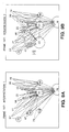
- Figures 7a-7e reveals the state of QSM 136 in frames 182-184 for a receding object.
- Scene 130 of Figure 7a which is of an original edge image with selected point features, contains a number of stationary points 1-23 and 25-30 and one moving point 24 which belongs to another vehicle that has passed the ALV 124 and is moving away from camera 122.
- the parameters of the ALV's self motion are computed with respect to a set of environmental features believed to be stationary. This set is defined by the hypotheses currently contained in the qualitative scene 136 model and described above.
- Figure 7b reveals the basis for computation of self motion with the original set of displacement vectors 120 (solid lines) between frames 182 and 183 ( Figure 6), fuzzy FOE 118 (shaded area), and "derotated" displacement vectors 138 (dotted lines).
- the rotation scale 142 in the lower left-hand corner indicates a horizontal rotation angle ⁇ (between the two frames) of almost 1° to the left. Vertical rotation ⁇ is not significant.
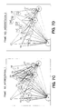
- Figures 7c and 7d visualize two separate but feasible scene interpretations 1 and 2 for the situation in frame 183.
- Entities which are considered stationary are marked with circles or plain labels.
- Arcs from a small circle (e.g., 1) or plain label to a larger circle (e.g., 4) indicate that a CLOSER-relationship has been established between the two entities.
- the entity with the larger circle is considered closer to camera 122 ( Figure 2) in the 3-D scene 130.
- Mobile entities i.e., 24 or 8, 11, 19, 20, 22 and 23
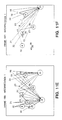
- Figures 8a-8d, 9a and 9b The second example of an approaching object, illustrated in Figures 8a-8d, 9a and 9b, is taken at frame 196 of the same image sequence as before ( Figure 6).
- Figure 8a shows the original edge image 131 with labeled points 8, 15, 19-24, 32, 33, 36, 39, 47, 49, 50, 56, 57, 59, 60, 63, 66, 71, and 73-77.
- Figure 8b shows the results of the FOE computation 116 with original displacement vectors (solid lines) 120, the fuzzy FOE (shaded area) 118, camera rotations ⁇ and ⁇ , and derotated displacement vectors (dotted lines) 138.
- the last example illustrates the fact that some forms of object motion are difficult or even impossible to detect from single point features. For example, an entity approaching camera 122 along a straight line parallel to the viewing direction cannot be distinguished from a stationary point when both camera 122 and the object move uniformly. Such a situation was given in the second example, where another car approached ALV 124. Here, heuristic reasoning about the general spatial layout of the scene was used to detect this motion indirectly.
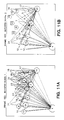
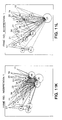
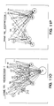
- Figures 11a-11r show the continuous development of the qualitative scene model for the sequence shown in Figures 6a-6h. Note that from frame 184 to 194 ( Figures 11c-11m) only one interpretation is presumed and the other is discarded. The final scene interpretation for a latter frame of the sequence is interpretation 1 for frame 197 ( Figure 11r). Interpretation 2 for frame 197 ( Figure 9b) is discarded.
Landscapes
- Engineering & Computer Science (AREA)
- Physics & Mathematics (AREA)
- General Physics & Mathematics (AREA)
- Theoretical Computer Science (AREA)
- Computer Vision & Pattern Recognition (AREA)
- Multimedia (AREA)
- Image Analysis (AREA)
- Image Processing (AREA)
- Control Of Position Or Direction (AREA)
- Length Measuring Devices By Optical Means (AREA)
Applications Claiming Priority (2)
| Application Number | Priority Date | Filing Date | Title |
|---|---|---|---|
| US07/331,706 US5036474A (en) | 1989-03-31 | 1989-03-31 | Motion detection and tracking from a mobile platform |
| US331706 | 1989-03-31 |
Publications (2)
| Publication Number | Publication Date |
|---|---|
| EP0390050A2 true EP0390050A2 (fr) | 1990-10-03 |
| EP0390050A3 EP0390050A3 (fr) | 1993-08-04 |
Family
ID=23295025
Family Applications (1)
| Application Number | Title | Priority Date | Filing Date |
|---|---|---|---|
| EP19900105761 Withdrawn EP0390050A3 (fr) | 1989-03-31 | 1990-03-27 | Méthode et appareil pour la détection de mouvement et la poursuite |
Country Status (4)
| Country | Link |
|---|---|
| US (1) | US5036474A (fr) |
| EP (1) | EP0390050A3 (fr) |
| JP (1) | JPH03223971A (fr) |
| IL (1) | IL93519A0 (fr) |
Cited By (5)
| Publication number | Priority date | Publication date | Assignee | Title |
|---|---|---|---|---|
| EP0600585A3 (fr) * | 1992-11-20 | 1994-11-02 | Mutoh Ind Ltd | Système pour identifier des dessins à main. |
| FR2721124A1 (fr) * | 1994-06-14 | 1995-12-15 | Thomson Csf | Procédé d'acquisition d'une cible dans une séquence d'images. |
| EP1257971A4 (fr) * | 1999-11-26 | 2005-07-06 | Mobileye Inc | Systeme et procede d'estimation de l'auto-deplacement d'un vehicule en mouvement au moyen d'images successives enregistrees le long de la trajectoire de deplacement du vehicule |
| EP2128821A4 (fr) * | 2007-01-30 | 2011-05-04 | Aisin Seiki | Dispositif de reconnaissance d'objet en mouvement |
| EP2081154A4 (fr) * | 2006-10-06 | 2011-05-04 | Aisin Seiki | Dispositif de reconnaisance d'un objet mobile, procédé de reconnaisance d'un objet mobile, et programme informatique |
Families Citing this family (28)
| Publication number | Priority date | Publication date | Assignee | Title |
|---|---|---|---|---|
| US5280565A (en) * | 1989-03-10 | 1994-01-18 | Mitsubishi Denki Kabushiki Kaisha | Fuzzy backward reasoning device |
| US5289563A (en) * | 1990-03-08 | 1994-02-22 | Mitsubishi Denki Kabushiki Kaisha | Fuzzy backward reasoning device |
| JPH0812072B2 (ja) * | 1990-06-13 | 1996-02-07 | 三菱電機株式会社 | 距離測定装置 |
| US5257209A (en) * | 1990-06-26 | 1993-10-26 | Texas Instruments Incorporated | Optical flow computation for moving sensors |
| JP2623157B2 (ja) * | 1990-07-13 | 1997-06-25 | 株式会社イセキ開発工機 | 移動物体の操縦装置 |
| JP2769052B2 (ja) * | 1991-04-09 | 1998-06-25 | インターナショナル・ビジネス・マシーンズ・コーポレイション | 自律移動機械、移動機械の制御装置及び方法 |
| DE69233722T2 (de) * | 1991-09-12 | 2009-02-12 | Fujifilm Corp. | Verfahren zur Ermittlung von Objektbildern und Verfahren zur Bestimmung der Bewegung davon |
| US5576972A (en) * | 1992-05-08 | 1996-11-19 | Harrison; Dana C. | Intelligent area monitoring system |
| US5517429A (en) * | 1992-05-08 | 1996-05-14 | Harrison; Dana C. | Intelligent area monitoring system |
| GB2278513B (en) * | 1993-04-29 | 1997-07-09 | British Aerospace | Tracking apparatus |
| US5414643A (en) * | 1993-06-14 | 1995-05-09 | Hughes Aircraft Company | Method and apparatus for continuous time representation of multiple hypothesis tracking data |
| US5469374A (en) * | 1993-06-23 | 1995-11-21 | The United States Of America As Represented By The Secretary Of The Navy | Automatic data segmentation module for target motion analysis applications |
| US5455938A (en) * | 1994-09-14 | 1995-10-03 | Ahmed; Sultan | Network based machine instruction generator for design verification |
| US5559695A (en) * | 1994-12-27 | 1996-09-24 | Hughes Aircraft Company | Apparatus and method for self-calibrating visual time-to-contact sensor |
| US5801970A (en) * | 1995-12-06 | 1998-09-01 | Martin Marietta Corporation | Model-based feature tracking system |
| US7003134B1 (en) * | 1999-03-08 | 2006-02-21 | Vulcan Patents Llc | Three dimensional object pose estimation which employs dense depth information |
| US7030875B2 (en) * | 2002-09-04 | 2006-04-18 | Honda Motor Company Ltd. | Environmental reasoning using geometric data structure |
| US7248718B2 (en) * | 2004-02-19 | 2007-07-24 | Siemens Corporate Research, Inc. | System and method for detecting a passing vehicle from dynamic background using robust information fusion |
| US7639841B2 (en) * | 2004-12-20 | 2009-12-29 | Siemens Corporation | System and method for on-road detection of a vehicle using knowledge fusion |
| EP1913557B1 (fr) * | 2005-06-23 | 2016-06-01 | Israel Aerospace Industries Ltd. | Systeme et procede de poursuite d'objets mobiles |
| JP5112666B2 (ja) * | 2006-09-11 | 2013-01-09 | 株式会社日立製作所 | 移動装置 |
| JP4794510B2 (ja) * | 2007-07-04 | 2011-10-19 | ソニー株式会社 | カメラシステムおよびカメラの取り付け誤差の補正方法 |
| CN101840578B (zh) * | 2009-03-17 | 2012-05-23 | 鸿富锦精密工业(深圳)有限公司 | 摄像装置及其动态侦测方法 |
| IL219639A (en) | 2012-05-08 | 2016-04-21 | Israel Aerospace Ind Ltd | Remote object tracking |
| US10212396B2 (en) | 2013-01-15 | 2019-02-19 | Israel Aerospace Industries Ltd | Remote tracking of objects |
| IL224273B (en) | 2013-01-17 | 2018-05-31 | Cohen Yossi | Delay compensation during remote sensor control |
| KR102077498B1 (ko) * | 2013-05-13 | 2020-02-17 | 한국전자통신연구원 | 상호 기하 관계가 고정된 카메라 군의 이동 경로 추출 장치 및 방법 |
| US11127283B2 (en) * | 2016-07-25 | 2021-09-21 | Drb Systems, Llc | Systems and methods to prevent carwash collisions |
Family Cites Families (3)
| Publication number | Priority date | Publication date | Assignee | Title |
|---|---|---|---|---|
| GB1568058A (en) * | 1975-11-21 | 1980-05-21 | Emi Ltd | Tracking and/or huidance systems |
| FR2378318A1 (fr) * | 1977-01-21 | 1978-08-18 | Thomson Csf | Systeme de poursuite d'une cible mobile |
| US4270143A (en) * | 1978-12-20 | 1981-05-26 | General Electric Company | Cross-correlation video tracker and method |
-
1989
- 1989-03-31 US US07/331,706 patent/US5036474A/en not_active Expired - Fee Related
-
1990
- 1990-02-25 IL IL93519A patent/IL93519A0/xx active IP Right Review Request
- 1990-03-27 EP EP19900105761 patent/EP0390050A3/fr not_active Withdrawn
- 1990-03-30 JP JP2084804A patent/JPH03223971A/ja active Pending
Non-Patent Citations (1)
| Title |
|---|
| PROCEEDINGS OF THE CONFERENCE ON COMPUTER VISION AND PATTERN RECOGNITION, ANN ARBOR, JUNE 5-9 1988; IEEE COMPUTER SOCIETY PRESS,WASHINGTON (US) pages 736 - 741 W. BURGER ET AL. 'Dynamic scene understanding for autonomous mobile robots' * |
Cited By (7)
| Publication number | Priority date | Publication date | Assignee | Title |
|---|---|---|---|---|
| EP0600585A3 (fr) * | 1992-11-20 | 1994-11-02 | Mutoh Ind Ltd | Système pour identifier des dessins à main. |
| FR2721124A1 (fr) * | 1994-06-14 | 1995-12-15 | Thomson Csf | Procédé d'acquisition d'une cible dans une séquence d'images. |
| EP1257971A4 (fr) * | 1999-11-26 | 2005-07-06 | Mobileye Inc | Systeme et procede d'estimation de l'auto-deplacement d'un vehicule en mouvement au moyen d'images successives enregistrees le long de la trajectoire de deplacement du vehicule |
| EP2081154A4 (fr) * | 2006-10-06 | 2011-05-04 | Aisin Seiki | Dispositif de reconnaisance d'un objet mobile, procédé de reconnaisance d'un objet mobile, et programme informatique |
| US8290209B2 (en) | 2006-10-06 | 2012-10-16 | Aisin Seiki Kabushiki Kaisha | Mobile object recognizing device, mobile object recognizing method, and computer program thereof |
| EP2128821A4 (fr) * | 2007-01-30 | 2011-05-04 | Aisin Seiki | Dispositif de reconnaissance d'objet en mouvement |
| US8184857B2 (en) | 2007-01-30 | 2012-05-22 | Aisin Seiki Kabushiki Kaisha | Moving object recognizing apparatus |
Also Published As
| Publication number | Publication date |
|---|---|
| IL93519A0 (en) | 1990-11-29 |
| JPH03223971A (ja) | 1991-10-02 |
| EP0390050A3 (fr) | 1993-08-04 |
| US5036474A (en) | 1991-07-30 |
Similar Documents
| Publication | Publication Date | Title |
|---|---|---|
| US5036474A (en) | Motion detection and tracking from a mobile platform | |
| US10275649B2 (en) | Apparatus of recognizing position of mobile robot using direct tracking and method thereof | |
| Burger et al. | Estimating 3D egomotion from perspective image sequence | |
| US5144685A (en) | Landmark recognition for autonomous mobile robots | |
| Janabi-Sharifi et al. | Automatic selection of image features for visual servoing | |
| EP3159121A1 (fr) | Dispositif de mise à jour de carte de robot mobile et procédé associé | |
| US20170151675A1 (en) | Apparatus for recognizing position of mobile robot using edge based refinement and method thereof | |
| Dickinson et al. | Integrating qualitative and quantitative shape recovery | |
| McGreavy et al. | Next best view planning for object recognition in mobile robotics | |
| CN119871410B (zh) | 机器人操作方法、机器人、介质、设备和程序产品 | |
| CN118999577A (zh) | 位姿估计方法、装置、机器人及存储介质 | |
| CN114694018B (zh) | 一种对象信息检测方法、装置和存储介质 | |
| Wong et al. | Scene reconstruction and robot navigation using dynamic fields | |
| Burger et al. | Dynamic scene understanding for autonomous mobile robots. | |
| Burger et al. | Qualitative understanding of scene dynamics for mobile robots | |
| Frau et al. | A robust tracking system for mobile robot guidance | |
| Lam et al. | Hypothesis verification using parametric models and active vision strategies | |
| Bhanu et al. | Dynamic-scene and motion analysis using passive sensors I. A qualitative approach | |
| Liski | 3-D collision checking for improving machine operator's spatial awareness | |
| Kak et al. | SN Gottschlich, and KD Smith | |
| Kak et al. | Coordinated Use of Multiple Sensors in a Robotic Workcell | |
| Wilkes et al. | Navigation based on a network of 2D images | |
| Dawson et al. | 3-D object recognition using passively sensed range data | |
| David et al. | Evaluation of the softposit model-to-image registration algorithm | |
| Roui-Abidi | Automatic sensor placement for volumetric object characterization |
Legal Events
| Date | Code | Title | Description |
|---|---|---|---|
| PUAI | Public reference made under article 153(3) epc to a published international application that has entered the european phase |
Free format text: ORIGINAL CODE: 0009012 |
|
| AK | Designated contracting states |
Kind code of ref document: A2 Designated state(s): DE FR GB NL SE |
|
| PUAL | Search report despatched |
Free format text: ORIGINAL CODE: 0009013 |
|
| AK | Designated contracting states |
Kind code of ref document: A3 Designated state(s): DE FR GB NL SE |
|
| STAA | Information on the status of an ep patent application or granted ep patent |
Free format text: STATUS: THE APPLICATION IS DEEMED TO BE WITHDRAWN |
|
| 18D | Application deemed to be withdrawn |
Effective date: 19940422 |