EP0390176A2 - Méthode d'investigation et appareil RMN - Google Patents
Méthode d'investigation et appareil RMN Download PDFInfo
- Publication number
- EP0390176A2 EP0390176A2 EP90106082A EP90106082A EP0390176A2 EP 0390176 A2 EP0390176 A2 EP 0390176A2 EP 90106082 A EP90106082 A EP 90106082A EP 90106082 A EP90106082 A EP 90106082A EP 0390176 A2 EP0390176 A2 EP 0390176A2
- Authority
- EP
- European Patent Office
- Prior art keywords
- timing
- sample
- tested
- influence
- chemical shift
- Prior art date
- Legal status (The legal status is an assumption and is not a legal conclusion. Google has not performed a legal analysis and makes no representation as to the accuracy of the status listed.)
- Granted
Links
- 238000012360 testing method Methods 0.000 title claims abstract description 24
- 239000000126 substance Substances 0.000 claims abstract description 51
- 230000035699 permeability Effects 0.000 claims abstract description 49
- 238000005481 NMR spectroscopy Methods 0.000 claims abstract description 47
- 238000009826 distribution Methods 0.000 claims abstract description 47
- 239000000523 sample Substances 0.000 claims abstract description 43
- 239000013074 reference sample Substances 0.000 claims abstract description 24
- 230000003068 static effect Effects 0.000 claims description 17
- 230000004907 flux Effects 0.000 claims description 15
- 238000000034 method Methods 0.000 description 6
- 238000001208 nuclear magnetic resonance pulse sequence Methods 0.000 description 5
- 239000000463 material Substances 0.000 description 4
- 238000003745 diagnosis Methods 0.000 description 2
- 238000003384 imaging method Methods 0.000 description 2
- 238000005259 measurement Methods 0.000 description 2
- UFHFLCQGNIYNRP-UHFFFAOYSA-N Hydrogen Chemical compound [H][H] UFHFLCQGNIYNRP-UHFFFAOYSA-N 0.000 description 1
- OAICVXFJPJFONN-UHFFFAOYSA-N Phosphorus Chemical compound [P] OAICVXFJPJFONN-UHFFFAOYSA-N 0.000 description 1
- 238000004458 analytical method Methods 0.000 description 1
- 239000008280 blood Substances 0.000 description 1
- 210000004369 blood Anatomy 0.000 description 1
- 230000002490 cerebral effect Effects 0.000 description 1
- 238000010586 diagram Methods 0.000 description 1
- 229910052739 hydrogen Inorganic materials 0.000 description 1
- 239000001257 hydrogen Substances 0.000 description 1
- 229910052698 phosphorus Inorganic materials 0.000 description 1
- 239000011574 phosphorus Substances 0.000 description 1
Images


Classifications
-
- G—PHYSICS
- G01—MEASURING; TESTING
- G01R—MEASURING ELECTRIC VARIABLES; MEASURING MAGNETIC VARIABLES
- G01R33/00—Arrangements or instruments for measuring magnetic variables
- G01R33/20—Arrangements or instruments for measuring magnetic variables involving magnetic resonance
- G01R33/44—Arrangements or instruments for measuring magnetic variables involving magnetic resonance using nuclear magnetic resonance [NMR]
- G01R33/48—NMR imaging systems
- G01R33/54—Signal processing systems, e.g. using pulse sequences ; Generation or control of pulse sequences; Operator console
- G01R33/56—Image enhancement or correction, e.g. subtraction or averaging techniques, e.g. improvement of signal-to-noise ratio and resolution
- G01R33/565—Correction of image distortions, e.g. due to magnetic field inhomogeneities
- G01R33/56527—Correction of image distortions, e.g. due to magnetic field inhomogeneities due to chemical shift effects
-
- G—PHYSICS
- G01—MEASURING; TESTING
- G01R—MEASURING ELECTRIC VARIABLES; MEASURING MAGNETIC VARIABLES
- G01R33/00—Arrangements or instruments for measuring magnetic variables
- G01R33/20—Arrangements or instruments for measuring magnetic variables involving magnetic resonance
- G01R33/44—Arrangements or instruments for measuring magnetic variables involving magnetic resonance using nuclear magnetic resonance [NMR]
- G01R33/48—NMR imaging systems
- G01R33/483—NMR imaging systems with selection of signals or spectra from particular regions of the volume, e.g. in vivo spectroscopy
- G01R33/485—NMR imaging systems with selection of signals or spectra from particular regions of the volume, e.g. in vivo spectroscopy based on chemical shift information [CSI] or spectroscopic imaging, e.g. to acquire the spatial distributions of metabolites
Definitions
- the present invention relates to a method and apparatus for imaging or visualising the distribution relative to the component e.g. hydrogen and phosphorus contained in an object to be tested, i.e. sample by use of nuclear magnetic resonance (NMR), and more particularly to a testing method and apparatus by use of NMR which is suitable to decide the values of permeability and chemical shift in the sample and to image their distribution.
- NMR nuclear magnetic resonance
- This related art has the following disadvantage. Although it apparently displays the permeability distribution, actually it only displays simultaneously the phase distributions due to the permeability distribution and to the chemical shift; the former and the latter are discriminated so that the values of the permeability and the chemical shift can not be determined.
- the present invention intends to extract only the phase information due to permeability distribution, display an image containing the phase information due to only chemical shift using the extracted information, and provide a method and apparatus for acquiring the values of the permeability and the chemical shift and their distribution.
- the image (tomogram) constructed using an NMR signal is based on the absolute value expressed in vector form.
- This vector information includes the phase components due to the following three influences depending upon the detecting timings of the NMR signal.
- the phase of point A is determined by the components 1, 2, and 3 as shown in Fig. 1B.
- the NMR signal in the site abundant in blood is greatly influenced from the component 2; in order to determine the molecular structure of a sample to be tested, the phase information influenced from the above item 3 is required.
- the present invention intends to provide a method and apparatus for separating items of phase information due to the influence from the above items 2 and 3 to individually extract the items of phase information.
- phase ⁇ ⁇ T ⁇ B0 (1)
- ⁇ B0 a difference between the magnetic flux densities within the above samples 1 and 2
- ⁇ is a proportional constant
- T is a time interval depending upon the timing of detecting an NMR signal and so the time passed from the detecting timing a in Fig. 4.
- phase of the image information and the magnetic flux density are in a proportional relationship so that the phase computed can be easily transformed into the magnetic flux density, and vice versa.
- the rotating speed of the nuclear spin after excited depends on the value of the chemical shift.
- the other nuclear spin rotates at the speed relative to that of the one nuclear spin.
- both nuclear spins overlap at the position of the phase zero, as shown in Fig. 2B, when a certain time (T2) is passed after the time when TE/2 has passed after the application of a 180° pulse so that the NMR signal reaches the maximum level. Then, if the NMR signal is measured, the phase information free from the influence from the chemical shift.
- the information thus obtained includes the influence from 1 (2) when measured at the other time, the information includes the influence from 1′ (3) (1′ is due to the difference in the measuring timing)
- the information thus obtained includes the influence from 1 and 2 (4) when measured at the other time, the information thus obtained includes the influence from 1′, 2′ and 3 (5) (1′ and 2′ are due to the difference in the measuring timing)
- Equation (4) - Equation (2) provides the phase information including the influence from 2
- Equation (5) - Equation (3) provides the phase information including the influence from 2′ and 3. Further, the relationship between 2 and 2′ can be computed, and consequently the phase information including the influence from 3.
- FIG. 3 shows the arrangement of the testing system using NMR according to one embodiment of the present invention.
- a control device 1 provides several kinds of instructions to the devices described below at a prescribed timing.
- the output from a high frequency pulse generator 2, which is amplified by an amplifier 3, excites a coil 4.
- the signal component received by the coil 4 is amplified by an amplifier 5.
- the signal component amplified is detected by a detector 6.
- the detected signal is converted into an image by a signal processor 7.
- Gradient magnetic fields in a Z-axis direction of three-dimention coordinate and the directions perpendicular thereto are generated by coils 8, 9 and 10 which are driven by gradient magnetic field generators 11, 12 and 13, respectively.
- a static magnetic field is generated by a coil 14 which is driven by a power supply 15.
- the coil 9 has the same shape as the coil 10 and is 90° rotated around the Z-axis for the coil 9; the coils 9 and generate the gradient magnetic fields perpendicular to each other.
- An object 16 to be tested e.g. living body
- a bed 17 which moves on a support 18.
- 19 is a device for supplying the data on the structure of the object to be tested.
- Fig. 4 is a timing chart showing the pulse sequence used in the testing method according to the present invention.
- the NMR signal at the maximum level can be measured at timing a , it does not include any of the components 1, 2 and 3. For this reason, in accordance with the present invention, the NMR signal is measured at the timing other than the timing a .
- the NMR signal free from the influence from the component 3 i.e. chemical shift can be measured.
- the phase information expressed by Equations (3) and (5) can be acquired. This timing c may be any other timing than the timings a and b .
- E st (x, y) represents the nonuniformity of the static magnetic field applied from outside of the sample to be tested
- E per (x, y) represents change in the magnetic flux density due to the distribution of the permeability of the sample to be tested.
- R (x, y) exp ⁇ -j ⁇ E per (x, y) ⁇ T2 + j ( ⁇ a ′ - ⁇ r ′) ⁇ (14)
- Equation (17) includes the phase components 2′ and 3 in Equation (5).
- the influence from the chemical shift is included in the phase j ⁇ c .
- the fixed value ( ⁇ a - ⁇ r ) can be deleted by calculating.
- the permeability distribution and its value can be determined using E per (x, y) acquired from Equation (16) in the following process.
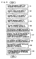
- FIG. 5 The flowchart of the testing method according to the present invention is shown in Fig. 5. The following operations are performed in respective steps.
Landscapes
- Physics & Mathematics (AREA)
- General Physics & Mathematics (AREA)
- High Energy & Nuclear Physics (AREA)
- Condensed Matter Physics & Semiconductors (AREA)
- Spectroscopy & Molecular Physics (AREA)
- Nuclear Medicine, Radiotherapy & Molecular Imaging (AREA)
- Radiology & Medical Imaging (AREA)
- Engineering & Computer Science (AREA)
- Signal Processing (AREA)
- General Health & Medical Sciences (AREA)
- Health & Medical Sciences (AREA)
- Optics & Photonics (AREA)
- Magnetic Resonance Imaging Apparatus (AREA)
Applications Claiming Priority (2)
| Application Number | Priority Date | Filing Date | Title |
|---|---|---|---|
| JP1078229A JPH02257934A (ja) | 1989-03-31 | 1989-03-31 | 核磁気共鳴を用いた検査方法及び装置 |
| JP78229/89 | 1989-03-31 |
Publications (3)
| Publication Number | Publication Date |
|---|---|
| EP0390176A2 true EP0390176A2 (fr) | 1990-10-03 |
| EP0390176A3 EP0390176A3 (fr) | 1991-08-14 |
| EP0390176B1 EP0390176B1 (fr) | 1996-12-04 |
Family
ID=13656217
Family Applications (1)
| Application Number | Title | Priority Date | Filing Date |
|---|---|---|---|
| EP90106082A Expired - Lifetime EP0390176B1 (fr) | 1989-03-31 | 1990-03-29 | Méthode d'investigation et appareil RMN |
Country Status (4)
| Country | Link |
|---|---|
| US (1) | US5065097A (fr) |
| EP (1) | EP0390176B1 (fr) |
| JP (1) | JPH02257934A (fr) |
| DE (1) | DE69029284T2 (fr) |
Cited By (1)
| Publication number | Priority date | Publication date | Assignee | Title |
|---|---|---|---|---|
| EP0497402B1 (fr) * | 1991-01-28 | 1996-09-04 | Koninklijke Philips Electronics N.V. | Procédé et dispositif de résonance magnétique pour réduire des défauts d'image dans une image de résonance magnétique |
Families Citing this family (1)
| Publication number | Priority date | Publication date | Assignee | Title |
|---|---|---|---|---|
| AU7554894A (en) * | 1993-08-06 | 1995-02-28 | Government Of The United States Of America, As Represented By The Secretary Of The Department Of Health And Human Services, The | Method and system for measuring the diffusion tensor and for diffusion tension imaging |
Family Cites Families (4)
| Publication number | Priority date | Publication date | Assignee | Title |
|---|---|---|---|---|
| US4719423A (en) * | 1985-08-13 | 1988-01-12 | Shell Oil Company | NMR imaging of materials for transport properties |
| JPS62148658A (ja) * | 1985-12-23 | 1987-07-02 | 株式会社日立製作所 | 核磁気共鳴を用いた検査方法 |
| US4769602A (en) * | 1986-07-02 | 1988-09-06 | Shell Oil Company | Determining multiphase saturations by NMR imaging of multiple nuclides |
| US4885539A (en) * | 1988-06-06 | 1989-12-05 | General Electric Company | Volume NMR coil for optimum signal-to-noise ratio |
-
1989
- 1989-03-31 JP JP1078229A patent/JPH02257934A/ja active Pending
-
1990
- 1990-03-29 US US07/500,901 patent/US5065097A/en not_active Expired - Lifetime
- 1990-03-29 DE DE69029284T patent/DE69029284T2/de not_active Expired - Fee Related
- 1990-03-29 EP EP90106082A patent/EP0390176B1/fr not_active Expired - Lifetime
Cited By (1)
| Publication number | Priority date | Publication date | Assignee | Title |
|---|---|---|---|---|
| EP0497402B1 (fr) * | 1991-01-28 | 1996-09-04 | Koninklijke Philips Electronics N.V. | Procédé et dispositif de résonance magnétique pour réduire des défauts d'image dans une image de résonance magnétique |
Also Published As
| Publication number | Publication date |
|---|---|
| EP0390176A3 (fr) | 1991-08-14 |
| EP0390176B1 (fr) | 1996-12-04 |
| JPH02257934A (ja) | 1990-10-18 |
| DE69029284D1 (de) | 1997-01-16 |
| DE69029284T2 (de) | 1997-06-12 |
| US5065097A (en) | 1991-11-12 |
Similar Documents
| Publication | Publication Date | Title |
|---|---|---|
| US7141970B2 (en) | Magnetic resonance imaging device | |
| EP0122593B1 (fr) | Appareil et procédé de production d'image par résonance magnétique nucléaire | |
| JPH0348814B2 (fr) | ||
| EP0167350B1 (fr) | Procédé et appareil de résonance magnétique nucléaire | |
| US4472683A (en) | Imaging apparatus using nuclear magnetic resonance | |
| US4520828A (en) | Nuclear magnetic resonance method and apparatus | |
| EP0100183B1 (fr) | Procédé et appareil de résonance magnétique nucléaire | |
| EP0112663B1 (fr) | Procédé et appareil à résonance magnétique nucléaire | |
| JP2000185029A (ja) | 核スピン共鳴装置における渦電流を検出するための方法 | |
| JPH0243497B2 (fr) | ||
| US4733183A (en) | Nuclear magnetic resonance methods and apparatus | |
| US4642568A (en) | Nuclear magnetic resonance methods and apparatus | |
| JPH0747023B2 (ja) | 核磁気共鳴を用いた検査装置 | |
| JPH0357774B2 (fr) | ||
| US4646023A (en) | Nuclear magnetic resonance imaging | |
| JPS5991344A (ja) | 核磁気共鳴の方法および装置 | |
| EP0106472B1 (fr) | Procédé et appareil de résonance magnétique nucléaire | |
| US5065097A (en) | Testing method and apparatus by use of nmr | |
| US4760339A (en) | NMR imaging method | |
| JP2585278B2 (ja) | 核磁気共鳴を用いた検査装置 | |
| EP0217578B1 (fr) | Procédés et appareil de résonance magnétique nucléaire | |
| GB2161275A (en) | Nuclear magnetic resonance method and apparatus | |
| GB2127155A (en) | Flow determination by nuclear magnetic resonance | |
| JP2607466B2 (ja) | 核磁気共鳴を用いた検査装置 | |
| US4739265A (en) | NMR imaging method |
Legal Events
| Date | Code | Title | Description |
|---|---|---|---|
| PUAI | Public reference made under article 153(3) epc to a published international application that has entered the european phase |
Free format text: ORIGINAL CODE: 0009012 |
|
| AK | Designated contracting states |
Kind code of ref document: A2 Designated state(s): DE GB |
|
| 17P | Request for examination filed |
Effective date: 19901220 |
|
| PUAL | Search report despatched |
Free format text: ORIGINAL CODE: 0009013 |
|
| AK | Designated contracting states |
Kind code of ref document: A3 Designated state(s): DE GB |
|
| 17Q | First examination report despatched |
Effective date: 19941124 |
|
| GRAH | Despatch of communication of intention to grant a patent |
Free format text: ORIGINAL CODE: EPIDOS IGRA |
|
| GRAA | (expected) grant |
Free format text: ORIGINAL CODE: 0009210 |
|
| AK | Designated contracting states |
Kind code of ref document: B1 Designated state(s): DE GB |
|
| REF | Corresponds to: |
Ref document number: 69029284 Country of ref document: DE Date of ref document: 19970116 |
|
| PLBE | No opposition filed within time limit |
Free format text: ORIGINAL CODE: 0009261 |
|
| STAA | Information on the status of an ep patent application or granted ep patent |
Free format text: STATUS: NO OPPOSITION FILED WITHIN TIME LIMIT |
|
| 26N | No opposition filed | ||
| REG | Reference to a national code |
Ref country code: GB Ref legal event code: 732E |
|
| PGFP | Annual fee paid to national office [announced via postgrant information from national office to epo] |
Ref country code: GB Payment date: 20010511 Year of fee payment: 12 |
|
| PGFP | Annual fee paid to national office [announced via postgrant information from national office to epo] |
Ref country code: DE Payment date: 20010522 Year of fee payment: 12 |
|
| REG | Reference to a national code |
Ref country code: GB Ref legal event code: IF02 |
|
| PG25 | Lapsed in a contracting state [announced via postgrant information from national office to epo] |
Ref country code: GB Free format text: LAPSE BECAUSE OF NON-PAYMENT OF DUE FEES Effective date: 20020329 |
|
| PG25 | Lapsed in a contracting state [announced via postgrant information from national office to epo] |
Ref country code: DE Free format text: LAPSE BECAUSE OF NON-PAYMENT OF DUE FEES Effective date: 20021001 |
|
| GBPC | Gb: european patent ceased through non-payment of renewal fee |
Effective date: 20020329 |