EP0390243A2 - Joint mécanique - Google Patents
Joint mécanique Download PDFInfo
- Publication number
- EP0390243A2 EP0390243A2 EP90200585A EP90200585A EP0390243A2 EP 0390243 A2 EP0390243 A2 EP 0390243A2 EP 90200585 A EP90200585 A EP 90200585A EP 90200585 A EP90200585 A EP 90200585A EP 0390243 A2 EP0390243 A2 EP 0390243A2
- Authority
- EP
- European Patent Office
- Prior art keywords
- bellows unit
- retaining ring
- seal
- formation
- face member
- Prior art date
- Legal status (The legal status is an assumption and is not a legal conclusion. Google has not performed a legal analysis and makes no representation as to the accuracy of the status listed.)
- Withdrawn
Links
Images

Classifications
-
- F—MECHANICAL ENGINEERING; LIGHTING; HEATING; WEAPONS; BLASTING
- F16—ENGINEERING ELEMENTS AND UNITS; GENERAL MEASURES FOR PRODUCING AND MAINTAINING EFFECTIVE FUNCTIONING OF MACHINES OR INSTALLATIONS; THERMAL INSULATION IN GENERAL
- F16J—PISTONS; CYLINDERS; SEALINGS
- F16J15/00—Sealings
- F16J15/16—Sealings between relatively-moving surfaces
- F16J15/34—Sealings between relatively-moving surfaces with slip-ring pressed against a more or less radial face on one member
- F16J15/36—Sealings between relatively-moving surfaces with slip-ring pressed against a more or less radial face on one member connected by a diaphragm or bellow to the other member
- F16J15/363—Sealings between relatively-moving surfaces with slip-ring pressed against a more or less radial face on one member connected by a diaphragm or bellow to the other member the diaphragm or bellow being made of metal
-
- F—MECHANICAL ENGINEERING; LIGHTING; HEATING; WEAPONS; BLASTING
- F16—ENGINEERING ELEMENTS AND UNITS; GENERAL MEASURES FOR PRODUCING AND MAINTAINING EFFECTIVE FUNCTIONING OF MACHINES OR INSTALLATIONS; THERMAL INSULATION IN GENERAL
- F16L—PIPES; JOINTS OR FITTINGS FOR PIPES; SUPPORTS FOR PIPES, CABLES OR PROTECTIVE TUBING; MEANS FOR THERMAL INSULATION IN GENERAL
- F16L33/00—Arrangements for connecting hoses to rigid members; Rigid hose-connectors, i.e. single members engaging both hoses
- F16L33/18—Arrangements for connecting hoses to rigid members; Rigid hose-connectors, i.e. single members engaging both hoses characterised by the use of additional sealing means
Definitions
- the present invention relates to mechanical face seals and in particular to mechanical face seals in which one seal face member is secured in fluid tight manner with respect to one of a pair of relatively rotatable components, by means of a resilient bellows unit.
- the bellows unit In designing a resilient bellows unit for a mechanical face seal, it is necessary that the bellows unit be capable of withstanding the stresses imposed by compression of the bellows unit and the pressure differential that exists across the bellows unit, while having sufficiently low spring rate so that the bellows unit can be compressed to the required degree to permit relative movement of the seal face members to accommodate wear, without applying an excessive axial load across the seal face members. It is consequently desirable to design the bellows unit for operation near its upper stress limit. However due to manufacturing tolerances on the bellows, if the bellows is longer than nominal the extra compression of the bellows will impose additional stresses which may take it over the stress limit, so that the bellows is liable to fail. Furthermore, additional compression will increase the load on the seal face members thus increasing the wear rate.
- the present invention provides a mechanical face seal in which manufacturing tolerances in the bellows unit may be accommodated so that the degree of compression and resulting stress levels in the bellows unit can be optimised.
- the axial position at which the end of the bellows unit is secured to the plane cylindrical portion of the retaining ring may be adjusted to accommodate variations in the length of the bellows unit due to manufacturing tolerances.
- a bellows unit/retaining ring assembly may be preassembled so that it has a predetermined axial load at a predetermined working height.
- a method of producing a mechanical face seal in which a first seal face member is secured in fluid tight manner and fixed axial and rotational relationship to one of a pair of relatively rotatable components and a second seal face member is secured in fixed rotational relationship but movable axially of the other component by means of a resilient bellows unit, the bellows unit being secured to its associated component by means of a tubular retaining ring, characterised in that said method comprises; compressing the bellows unit axially to a predetermined axial load, locating a tubular retaining ring relative to the bellows unit so that a cylindrical face of a plane cylindrical portion of the retaining ring is engaged by one end of the bellows unit and the other end of the bellows unit is spaced axially of a locating formation on the retaining ring by a predetermined distance, and securing the end of the bellows unit to the cylindrical face of the plane cylindrical portion of the retaining ring in fluid tight manner.
- the retaining ring is a press fit with respect to the component with which it is associated and the first seal face member is located on a retaining sleeve which is a press fit with respect to the component with which it is associated.
- the retaining ring and retaining sleeve may then be mounted with respect to their respective components, by means of a press tool which engages the retaining ring and retaining sleeve in predetermined axial relationship, a load being applied to the press tool to force the retaining ring and retaining sleeve axially with respect to their associated components until the locating formation on the retaining ring is set to an axial position relative to any other datum, for example it abuts a corresponding formation on the component associated with the retaining ring or the press tool engages a stop on the press.
- the seal may be assembled so that the bellows is compressed to provide a predetermined load between the seal face members.
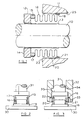
- a seal between a rotatable shaft 10 and a housing 11 comprises a first seal face member or seat 12 which is mounted in fixed axial and rotational relationship on the shaft 10.
- the seat 12 is located on a retaining sleeve 13 which is a press fit on shaft 10.
- the seat 12 is located axially of the sleeve 13 by means of a flange formation 14.
- the seat 12 may be an interference fit with respect to the sleeve 13 or may, for example, be sealed with respect thereto by means of an elastomeric cup rubber or be bonded thereto by a suitable adhesive or sealing compound.
- a second seal face member 15 is located at one end of a bellows unit 16, a cylindrical end formation 17 at that end of the bellows unit 16 forming a retainer for the seal face member 15.
- the seal face member 15 may be retained in formation 17 by an interference fit or by for example an adhesive or sealing compound.
- the other end of the bellows unit 16 has a cylindrical formation 18 which is a slight interference fit with a plane cylindrical portion 21 of a tubular retaining ring 20.
- the end formation 18 of the bellows unit 16 is secured to the plane cylindrical portion 21 of ring 20 in fluid tight manner, this may be achieved for example by means of welding, brazing or bonding with an adhesive.
- the retaining ring 20 is a press fit in bore 25 through the housing 11, which is coaxial with the shaft 10.
- sealing compound may be applied between the sleeve 13 and shaft 10 and/or between the ring 20 and housing 11.
- sealing means for example an O-ring located in an annular groove in the shaft 10 or housing 11 may be used to provide a seal between the shaft 10 and sleeve 13 or between the ring 20 and housing 11. Further sealing means may also be used to provide a seal between the seat 12 and sleeve 13 and/or between the seal face member 15 and bellows unit 16.
- the bellows unit/retaining ring assembly 16/20 used in the seal illustrated in Figure 1 is manufactured in the following stages;
- This method of manufacturing the bellows unit assembly 16/20 will ensure that at a predetermined load, the sealing face of seal face member 15 will be spaced accurately with respect to the locating flange 22, and tolerance variations in the length of the bellows unit 16 and retaining ring 20 are accommodated by varying the axial position at which end 18 of bellows unit 16 is secured to the cylindrical portion 21 of ring 20.
- the seal is installed by locating the flange 22 of ring 20 and flange 14 of sleeve 13 against axially separated shoulders of a ram and simultaneously pressing the sleeve 13 axially onto the shaft 10 and ring 20 axially into the bore 25 of housing 11 by means of said ram, until the flange 22 of ring 20 is seated against the housing 11.
- the seat 12 and seal face member 15 will then be located accurately relative to their associated components, so that compression of the bellows unit 16 will apply an axial force urging the seal face member 15 into sealing engagement with the seat 12, said force being sufficient to maintain sealing engagement between the seal face member 15 and seat 12 without causing excessive wear or over-stressing the bellows unit.
- the seal face member 15/bellows assembly 16 and seat 12/sleeve 13 assembly are preassembled concentrically of one another.
- the end 40 of sleeve 13 remote from seat 12 is swaged outwardly to form flange formation 41.
- the flange formation 41 is located such that it will engage the bellows unit 16 at the end thereof remote from seal face member 15 and hold the bellows in slight compression, so that seal face member 15 will engage seat 12.
- This unitised assembly may then be installed in the manner disclosed above, so that the flange 22 is located with respect to the housing and the sleeve 13 is located with respect to the shaft.
- the flange formation 41 is positioned so that when it engages the bellows unit 16, the bellows unit 16 is compressed to a lesser degree than that to which it is compressed over its operational range, when the seal is installed.
- the flange formation 41 will thereby be clear of the bellows unit 16 when the seal is installed and will not interfere with operation of the seal.
- the bellows unit is made of metal, any suitable resilient material may be used.
- the seal face member 15 is located in a formation 17 formed by the end of bellows unit 16, a separate retaining ring may be secured to the end of the bellows unit 16 for this purpose.
- the seat 12 may be secured to the shaft 10 by other means, for example retaining rings which are clamped to the shaft 10 in known manner.
- the seal face member 15 may be secured to the shaft 10 by means of the bellows unit/retaining ring assembly 16/20 while the seat 12 is secured to the housing 11 in suitable manner.
- the flange 22 abuts housing 11, the flange 22 may be located with respect to some other datum, for example to accommodate axial tolerances.
- a load cell 30 controls movement of the ram 31
- other means of control to apply a predetermined axial load to the bellows unit 16 may be used.
- the spatial relationship between the bellows unit and retaining ring may be achieved by other means, for example electro/mechanical devices.
Landscapes
- Engineering & Computer Science (AREA)
- General Engineering & Computer Science (AREA)
- Mechanical Engineering (AREA)
- Mechanical Sealing (AREA)
Applications Claiming Priority (2)
| Application Number | Priority Date | Filing Date | Title |
|---|---|---|---|
| GB898906901A GB8906901D0 (en) | 1989-03-28 | 1989-03-28 | Mechanical face seals |
| GB8906901 | 1989-03-28 |
Publications (2)
| Publication Number | Publication Date |
|---|---|
| EP0390243A2 true EP0390243A2 (fr) | 1990-10-03 |
| EP0390243A3 EP0390243A3 (fr) | 1991-07-17 |
Family
ID=10654010
Family Applications (1)
| Application Number | Title | Priority Date | Filing Date |
|---|---|---|---|
| EP19900200585 Withdrawn EP0390243A3 (fr) | 1989-03-28 | 1990-03-13 | Joint mécanique |
Country Status (8)
| Country | Link |
|---|---|
| EP (1) | EP0390243A3 (fr) |
| JP (1) | JPH02283972A (fr) |
| KR (1) | KR900014805A (fr) |
| AU (1) | AU5145290A (fr) |
| BR (1) | BR9001426A (fr) |
| CA (1) | CA2012724A1 (fr) |
| GB (2) | GB8906901D0 (fr) |
| ZA (1) | ZA902354B (fr) |
Cited By (4)
| Publication number | Priority date | Publication date | Assignee | Title |
|---|---|---|---|---|
| ES2048075A2 (es) * | 1990-11-02 | 1994-03-01 | Truetzschler Gmbh & Co Kg | Dispositivo para la estanqueizacion de un cilindro rotativo que conduce fibras, de una maquina para la elaboracion de hilaturas, por ejemplo, cardas, alimentadoras de carda y limpiadoras. |
| EP0992722A2 (fr) | 1998-10-07 | 2000-04-12 | Firma Carl Freudenberg | Garniture mécanique d'étanchéité |
| EP2853788A4 (fr) * | 2012-10-04 | 2016-03-16 | Eagle Ind Co Ltd | Joint d'étanchéité mécanique |
| EP3623669A4 (fr) * | 2017-05-12 | 2021-01-20 | Eagle Industry Co., Ltd. | Joint mécanique |
Families Citing this family (3)
| Publication number | Priority date | Publication date | Assignee | Title |
|---|---|---|---|---|
| JP5578903B2 (ja) * | 2010-03-25 | 2014-08-27 | 三菱重工業株式会社 | シール機構及び蒸気タービン |
| JP6256864B2 (ja) * | 2013-04-22 | 2018-01-10 | Nok株式会社 | スライドリングシール |
| WO2018207747A1 (fr) | 2017-05-12 | 2018-11-15 | イーグル工業株式会社 | Joint mécanique |
Family Cites Families (9)
| Publication number | Priority date | Publication date | Assignee | Title |
|---|---|---|---|---|
| GB518339A (en) * | 1938-09-09 | 1940-02-23 | Manchester Oil Refinery Ltd | Improvements in stuffing boxes or shaft sealing devices |
| GB667052A (en) * | 1949-09-21 | 1952-02-20 | Chiksan Co | Sealed swivel joint |
| GB737810A (en) * | 1953-02-20 | 1955-10-05 | Perfecting Service Company | Improvements in or relating to rotary connections for fluid conduits and the like |
| US3515394A (en) * | 1964-06-05 | 1970-06-02 | Sealol | Vibration damping means for resilient convoluted members |
| US3397894A (en) * | 1968-01-02 | 1968-08-20 | Chandler Evans Inc | Rotary shaft seal |
| US3612549A (en) * | 1970-05-25 | 1971-10-12 | Melvin H Berkowitz | Pressure seal |
| JPS5712305Y2 (fr) * | 1976-07-23 | 1982-03-11 | ||
| US4095808A (en) * | 1977-01-06 | 1978-06-20 | Cummins Engine Company, Inc. | Anti rotation seal assembly |
| US4163563A (en) * | 1978-04-12 | 1979-08-07 | Sealol, Inc. | Rotary bellows seal with vibration-damping means |
-
1989
- 1989-03-28 GB GB898906901A patent/GB8906901D0/en active Pending
-
1990
- 1990-03-12 GB GB9005506A patent/GB2229777A/en not_active Withdrawn
- 1990-03-13 EP EP19900200585 patent/EP0390243A3/fr not_active Withdrawn
- 1990-03-19 AU AU51452/90A patent/AU5145290A/en not_active Abandoned
- 1990-03-21 CA CA002012724A patent/CA2012724A1/fr not_active Abandoned
- 1990-03-26 KR KR1019900004024A patent/KR900014805A/ko not_active Withdrawn
- 1990-03-27 ZA ZA902354A patent/ZA902354B/xx unknown
- 1990-03-28 BR BR909001426A patent/BR9001426A/pt unknown
- 1990-03-28 JP JP2080575A patent/JPH02283972A/ja active Pending
Cited By (8)
| Publication number | Priority date | Publication date | Assignee | Title |
|---|---|---|---|---|
| ES2048075A2 (es) * | 1990-11-02 | 1994-03-01 | Truetzschler Gmbh & Co Kg | Dispositivo para la estanqueizacion de un cilindro rotativo que conduce fibras, de una maquina para la elaboracion de hilaturas, por ejemplo, cardas, alimentadoras de carda y limpiadoras. |
| EP0992722A2 (fr) | 1998-10-07 | 2000-04-12 | Firma Carl Freudenberg | Garniture mécanique d'étanchéité |
| DE19846153C1 (de) * | 1998-10-07 | 2000-04-20 | Freudenberg Carl Fa | Gleitringdichtung |
| US6338489B1 (en) | 1998-10-07 | 2002-01-15 | Firma Carl Freudenberg | Mechanical seal |
| EP2853788A4 (fr) * | 2012-10-04 | 2016-03-16 | Eagle Ind Co Ltd | Joint d'étanchéité mécanique |
| EP3159583A1 (fr) * | 2012-10-04 | 2017-04-26 | Eagle Industry Co., Ltd. | Joint mécanique |
| EP3623669A4 (fr) * | 2017-05-12 | 2021-01-20 | Eagle Industry Co., Ltd. | Joint mécanique |
| US11187326B2 (en) | 2017-05-12 | 2021-11-30 | Eagle Industry Co., Ltd. | Mechanical seal |
Also Published As
| Publication number | Publication date |
|---|---|
| AU5145290A (en) | 1990-10-04 |
| CA2012724A1 (fr) | 1990-09-28 |
| GB2229777A (en) | 1990-10-03 |
| BR9001426A (pt) | 1991-04-09 |
| EP0390243A3 (fr) | 1991-07-17 |
| JPH02283972A (ja) | 1990-11-21 |
| GB8906901D0 (en) | 1989-05-10 |
| GB9005506D0 (en) | 1990-05-09 |
| ZA902354B (en) | 1990-12-28 |
| KR900014805A (ko) | 1990-10-25 |
Similar Documents
| Publication | Publication Date | Title |
|---|---|---|
| US4687084A (en) | Clutch release apparatus for pull type clutches | |
| KR100582315B1 (ko) | 유압식 제어 디클러칭 장치 및 가이드 튜브의 제조 방법 | |
| US5568930A (en) | Joint assembly | |
| KR100310564B1 (ko) | 클러치의연결부상에견인작용하는유압액츄에이터를갖는클러치해제기구 | |
| CA2002662A1 (fr) | Collier annulaire pour ressort pneumatique | |
| EP0149908A3 (fr) | Groupe d'étanchéité pour vérin actionné par fluide | |
| US11808367B2 (en) | Valve, device for regulating the pressure of a flow medium using the valve, and device for securing the valve in a transmission component | |
| EP0390243A2 (fr) | Joint mécanique | |
| EP0588570B1 (fr) | Soupape | |
| EP0867647A3 (fr) | Joint en plastique préchargé par un ressort | |
| EP0864793A3 (fr) | Soupape de surpression | |
| EP1082519B1 (fr) | Membrane facile a monter | |
| JP2002535579A (ja) | 油圧制御式クラッチレリーズ装置 | |
| CA2267995C (fr) | Cylindre de frein a ressort accumulateur inviolable et a petite enveloppe | |
| EP0130137A1 (fr) | Moteur et dispositif de rattrapage de jeu d'un frein à disque | |
| US5673919A (en) | Sealing arrangement with elastomeric sleeve and surrounding receptacle supported by separate housing shoulders | |
| JP2535425Y2 (ja) | 管継手 | |
| US6209582B1 (en) | 2-way collar and O-ring seal assembly | |
| US4893782A (en) | Metallic seat for fluid valve | |
| US3545070A (en) | Method of assembling a vacuum modulator | |
| US6217029B1 (en) | Seal arrangement for a piston rod | |
| US4463958A (en) | Mechanical face seals | |
| CN221075903U (zh) | 装配结构和包括该装配结构的接触组件 | |
| GB2142104A (en) | A valve device for a vacuum brake booster | |
| CA2476946A1 (fr) | Garniture d'etancheite a bague munie d'un orifice de communication |
Legal Events
| Date | Code | Title | Description |
|---|---|---|---|
| PUAI | Public reference made under article 153(3) epc to a published international application that has entered the european phase |
Free format text: ORIGINAL CODE: 0009012 |
|
| AK | Designated contracting states |
Kind code of ref document: A2 Designated state(s): AT BE CH DE DK ES FR GB GR IT LI LU NL SE |
|
| PUAL | Search report despatched |
Free format text: ORIGINAL CODE: 0009013 |
|
| AK | Designated contracting states |
Kind code of ref document: A3 Designated state(s): AT BE CH DE DK ES FR GB GR IT LI LU NL SE |
|
| STAA | Information on the status of an ep patent application or granted ep patent |
Free format text: STATUS: THE APPLICATION IS DEEMED TO BE WITHDRAWN |
|
| 18D | Application deemed to be withdrawn |
Effective date: 19920118 |
|
| P01 | Opt-out of the competence of the unified patent court (upc) registered |
Effective date: 20230522 |