EP0390376A2 - Simulatoren für Prozesssensoren - Google Patents
Simulatoren für Prozesssensoren Download PDFInfo
- Publication number
- EP0390376A2 EP0390376A2 EP90302800A EP90302800A EP0390376A2 EP 0390376 A2 EP0390376 A2 EP 0390376A2 EP 90302800 A EP90302800 A EP 90302800A EP 90302800 A EP90302800 A EP 90302800A EP 0390376 A2 EP0390376 A2 EP 0390376A2
- Authority
- EP
- European Patent Office
- Prior art keywords
- signal
- output
- input
- terminals
- circuit
- Prior art date
- Legal status (The legal status is an assumption and is not a legal conclusion. Google has not performed a legal analysis and makes no representation as to the accuracy of the status listed.)
- Pending
Links
Images

Classifications
-
- G—PHYSICS
- G05—CONTROLLING; REGULATING
- G05B—CONTROL OR REGULATING SYSTEMS IN GENERAL; FUNCTIONAL ELEMENTS OF SUCH SYSTEMS; MONITORING OR TESTING ARRANGEMENTS FOR SUCH SYSTEMS OR ELEMENTS
- G05B19/00—Program-control systems
- G05B19/02—Program-control systems electric
- G05B19/04—Program control other than numerical control, i.e. in sequence controllers or logic controllers
- G05B19/042—Program control other than numerical control, i.e. in sequence controllers or logic controllers using digital processors
- G05B19/0423—Input/output
- G05B19/0425—Safety, monitoring
-
- G—PHYSICS
- G05—CONTROLLING; REGULATING
- G05B—CONTROL OR REGULATING SYSTEMS IN GENERAL; FUNCTIONAL ELEMENTS OF SUCH SYSTEMS; MONITORING OR TESTING ARRANGEMENTS FOR SUCH SYSTEMS OR ELEMENTS
- G05B17/00—Systems involving the use of models or simulators of said systems
- G05B17/02—Systems involving the use of models or simulators of said systems electric
-
- Y—GENERAL TAGGING OF NEW TECHNOLOGICAL DEVELOPMENTS; GENERAL TAGGING OF CROSS-SECTIONAL TECHNOLOGIES SPANNING OVER SEVERAL SECTIONS OF THE IPC; TECHNICAL SUBJECTS COVERED BY FORMER USPC CROSS-REFERENCE ART COLLECTIONS [XRACs] AND DIGESTS
- Y02—TECHNOLOGIES OR APPLICATIONS FOR MITIGATION OR ADAPTATION AGAINST CLIMATE CHANGE
- Y02B—CLIMATE CHANGE MITIGATION TECHNOLOGIES RELATED TO BUILDINGS, e.g. HOUSING, HOUSE APPLIANCES OR RELATED END-USER APPLICATIONS
- Y02B70/00—Technologies for an efficient end-user side electric power management and consumption
- Y02B70/30—Systems integrating technologies related to power network operation and communication or information technologies for improving the carbon footprint of the management of residential or tertiary loads, i.e. smart grids as climate change mitigation technology in the buildings sector, including also the last stages of power distribution and the control, monitoring or operating management systems at local level
-
- Y—GENERAL TAGGING OF NEW TECHNOLOGICAL DEVELOPMENTS; GENERAL TAGGING OF CROSS-SECTIONAL TECHNOLOGIES SPANNING OVER SEVERAL SECTIONS OF THE IPC; TECHNICAL SUBJECTS COVERED BY FORMER USPC CROSS-REFERENCE ART COLLECTIONS [XRACs] AND DIGESTS
- Y04—INFORMATION OR COMMUNICATION TECHNOLOGIES HAVING AN IMPACT ON OTHER TECHNOLOGY AREAS
- Y04S—SYSTEMS INTEGRATING TECHNOLOGIES RELATED TO POWER NETWORK OPERATION, COMMUNICATION OR INFORMATION TECHNOLOGIES FOR IMPROVING THE ELECTRICAL POWER GENERATION, TRANSMISSION, DISTRIBUTION, MANAGEMENT OR USAGE, i.e. SMART GRIDS
- Y04S20/00—Management or operation of end-user stationary applications or the last stages of power distribution; Controlling, monitoring or operating thereof
- Y04S20/20—End-user application control systems
Definitions
- the present invention is directed to transducer, or sensor, simulators primarily for use in testing process monitoring systems.
- monitoring installations are composed of one or more condition transducers, or sensors, and a system for monitoring the transducer output to provide desired information. There is frequently a need to test such a monitoring system with the transducers removed but based on the input signals which would be applied to the transducers during normal operation of the installation.
- components which can be adapted to simulate a variety of transducers there are many testing procedures which require, or would be aided by, components which can be adapted to simulate a variety of transducers.
- RTDs field mounted resistance temperature detectors
- a circuit device for simulating a selected one of a plurality of process transducers comprises: means defining signal input and output terminals connectable to external conductors; means defining a plurality of circuit components connectable between the signal input and output terminals; coupling means connected between two of the circuit components for conducting a signal between the two components; and selective connecting means including connector terminals connected to at least one of the circuit components, and connector elements for establishing conductive connections between selected ones of the connector terminals for configuring the circuit device to apply to the signal output terminal a signal corresponding to the output signal of a selected transducer.
- a testing system comprises a plurality of devices each as defined above; a circuit carrying all of the connector elements; control means connected for controlling the conductive connections established by the connector elements between selected ones of the connector terminals; and personal computer means connected to the signal input terminals of all of the devices for supplying input signals thereto and to the control means for supplying control signals designating the conductive connections which are to be established by the control means.
- the invention essentially relates to board-mounted interface circuits which serve to simulate a variety of field sensors such as those employed in a nuclear power plant. These circuits are useful for testing components or systems which, during normal operation, receive signals produced by such sensors.
- a simulator circuit according to the invention is generally composed of a plurality of parallel, structurally identical, channels each composed of a set of analog circuit devices. Each channel further includes jumper terminals which can be selectively connected to create a simulation of a particular type of sensor, or transducer.
- the circuit can easily be configured to simulate any desired group of sensors and the configurations can easily be altered as needed for different applications.
- Board-mounted circuits according to the invention can be employed in test fixtures for nuclear plant process instrumentation, card and burn-in test fixtures, training simulator fixtures and field diagnostic test equipment.
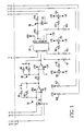
- FIG. 1 shows one preferred embodiment of a resistance temperature detector (RTD) simulator according to the invention.
- the terminals represented by arrows are connected to external plug-in contacts along one edge of the circuit board, while the terminals represented by small hollow circles are jumper contacts which may be connected together by appropriate shorting bars or relays mounted on a separate board.
- a first amplifier circuit 90 includes an operational amplifier (U1) connected as a current-voltage converter having an input terminal (9) connected to receive the operating current that would be applied to the RTD.
- Amplifier circuit 90 has a resistive feedback path composed of a first resistor R2 permanently connected across the amplifier (U1) and a second resistor R1 provided with associated jumper contacts for selectively connecting resistor R1 in parallel with resistor R2.
- an RTD having a base resistance of 200 ⁇ is simulated; when the jumper contacts are closed, the simulated RTD has a resistance of 100 ⁇ .
- Amplifier circuit 90 is coupled to a second amplifier circuit 92 via a coupling resistor R3 for supplying the output signal from amplifier circuit 90 to the input of an operational amplifier (U2) of second amplifier circuit 92.
- Second amplifier circuit 92 has a resistive feedback path which can be switched between either one of two resistance values, represented by resistors R4 and R5, by the connection of a shorting bar between two associated jumper contacts.
- Amplifier circuit 92 serves to define the temperature responsive resistance variation range of the RTD being simulated, connection of resistor R4 being associated with a wide range and connection of resistor R5 being associated with a narrow range.
- the output signal from amplifier circuit 92 is coupled via a conductor to one input of an analog multiplier 94, which can be constituted by an AD534 circuit.
- the other multiplier input is constituted by a voltage applied via external terminal 4, and the resulting product signal is applied to a proportional-integral (PI) network 95 between external terminals 5 and E.
- PI proportional-integral
- the voltage applied via external terminal 4 relates to the temperature value to be simulated and may be derived from a computer controllable voltage source or the wiper of a potentiometer whose resistance is connected between terminals 3 and C.
- the input and output voltage values associated with multiplier 94 may be calibrated by offset voltages supplied to multiplier 94 from associated potentiometers, as shown.
- amplifier circuit 92 is configured to control the output range of the simulated RTD, while the voltage applied via external terminal 4 constitutes a demand voltage which determines the output signal level within the selected range. More precisely, the output voltage from amplifier circuit 92 is representative of the current flowing through the RTD being simulated and the voltage applied via external terminal 4 is representative of the resistance which the RTD would have at a given temperature.
- Multiplier circuit 94 may be configured to produce an output voltage which is the product of the two input voltages divided by the maximum value of the voltage applied to external terminal 4.
- Other interface circuits are arranged to receive a potentiometer or other voltage type input and produce an output signal which can be configured to simulate the output of a thermocouple, a current transmitter, or a device producing an output voltage.
- These simulator circuits preferably include a test point in each channel which provides a voltage that is an accurate representation of the channel output signal and that can be measured without affecting the operation of the simulator circuit.
- One advantage of the circuits is that they do not require any adjustment controls.
- These circuits can selectively simulate either active or passive current transmitters, an active transmitter being one which has its own power supply and a passive transmitter being one which is supplied with power by the monitoring system.
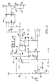
- the analog circuit devices forming the channel include an input amplifier 104, an optical coupler 106, a current control transistor 108, a power supply 110 and a plurality of resistors and diodes.
- Amplifier 104 is a differential amplifier having its inverting input connected via an input terminal 4 to the wiper of an external potentiometer (not shown).
- the potentiometer resistance is connected between terminals 3 and C.
- Such potentiometer connections can also be employed with respect to the correspondingly numbered external terminals of Figure 1.
- Coupler 106 which may be constituted by a 6N139 device, essentially includes an electro-optical input transducer, such as an LED, connected to the output of amplifier 104, an optoelectrical output transducer, such as a photodiode, and an optical fiber connected between the transducers.
- the purpose of coupler 106 is to electrically isolate the output of amplifier 104 from the circuit components downstream thereof.
- the output transducer of coupler 106 is connected to the base of a transistor 108, in this embodiment an npn transistor, which is supplied with an operating voltage by power supply 110 so that transistor 108 conducts a current proportional to the voltage applied to its base.
- This current flows through a resistor R13, which is preferably a precision resistor, producing a voltage drop which is proportional to the current through transistor 108.
- Power supply 110 is a dc/dc converter which receives operating power from an external source, shown connected to terminals +IN and -IN, and supplies regulated positive and negative output potentials at terminals V+ and V-.
- An operative circuit arrangement is completed by connecting together selected sets of jumper contacts 1-3, 7-20 and 72-75 by means of shorting bars.
- Simulation mode Jumper contacts to be shorted together Current transmitter 4-20ma active 2-3; 11-12; 13-14; 17-18; 72-73 4-20ma passive 2-3; 11-12; 13-14; 15-18; 72-73 10-50ma active 1-2; 11-12; 13-14; 15-16; 17-18; 72-73 10-50ma passive 1-2; 11-12; 13-14; 15-16-18; 72-73 Voltage generator, 1-10V 2-3; 7-8; 19-20; 9-10-14-18 Thermocouple 2-3; 7-8; 19-20; 9-10-74; 75-14-18
- Zener diode D9 is selected to have a higher breakdown voltage than Zener diode D1.
- Figures 1 and 2 include exemplary component values, it will be appreciated that the invention is not limited to circuits having those component values.
- Figure 3 illustrates, in block diagram form, a test system incorporating simulators of the type illustrated in Figures 1 and 2.
- the system includes an RTD board 120 containing two channels each having the form shown in Figure 1 and a simulator board 122 containing four channels each having the form shown in Figure 2.
- the jumper terminals illustrated in Figures 1 and 2 are brought to edge contacts which are connected, via a bus, to a jumper select unit mounted on a logic board 124.
- the jumper select unit is composed of a plurality of relays having their contacts connected, via the bus, to appropriate edge terminal contacts to establish the desired short circuits between appropriate sets of jumper terminals.
- Logic board 124 further includes an input decoder/receiver unit which controls the operation of the relays of the jumper select unit, as well as an output select unit which may also be composed of a plurality of relays controlled by the input decoder/receiver unit in order to connect the outputs of one or more of the channels on boards 120 and 122 to a terminal block 126 which is connected to the apparatus being tested.
- the illustrated system further includes a personal computer 130 provided with an interface board 132 via which information, in digital form, relating to the input levels to be applied to the channels is supplied. This information is conducted to a digital/analog converter board 134 connected to supply suitable analog input signals to all of the channels on boards 120 and 122.
- Personal computer 130 further includes a parallel output port 136 connected via a bus to supply control signals to the input decoder/receiver unit on board 124. The system is completed by an appropriate power supply 138.
- each simulator channel can be configured to correspond to a respectively different type of sensor and the signals applied to logic board 124 can serve to connect the output of one of the channels to terminal block 126.
- the signals applied to logic board 124 can serve to connect the output of one of the channels to terminal block 126.
Landscapes
- Physics & Mathematics (AREA)
- General Physics & Mathematics (AREA)
- Engineering & Computer Science (AREA)
- Automation & Control Theory (AREA)
- Testing Electric Properties And Detecting Electric Faults (AREA)
- Testing Or Calibration Of Command Recording Devices (AREA)
- Monitoring And Testing Of Nuclear Reactors (AREA)
- Electronic Switches (AREA)
Applications Claiming Priority (2)
| Application Number | Priority Date | Filing Date | Title |
|---|---|---|---|
| US07/330,545 US4922194A (en) | 1989-03-30 | 1989-03-30 | Process sensor simulators |
| US330545 | 1989-03-30 |
Publications (2)
| Publication Number | Publication Date |
|---|---|
| EP0390376A2 true EP0390376A2 (de) | 1990-10-03 |
| EP0390376A3 EP0390376A3 (de) | 1991-11-27 |
Family
ID=23290235
Family Applications (1)
| Application Number | Title | Priority Date | Filing Date |
|---|---|---|---|
| EP19900302800 Pending EP0390376A3 (de) | 1989-03-30 | 1990-03-15 | Simulatoren für Prozesssensoren |
Country Status (3)
| Country | Link |
|---|---|
| US (1) | US4922194A (de) |
| EP (1) | EP0390376A3 (de) |
| JP (1) | JPH02291998A (de) |
Cited By (2)
| Publication number | Priority date | Publication date | Assignee | Title |
|---|---|---|---|---|
| EP0610711A1 (de) * | 1993-02-12 | 1994-08-17 | Robert Bosch Gmbh | Elektronische Steuervorrichtung für einen elektromotorischen Antrieb, insbesondere Garagentorantrieb |
| WO2000070415A1 (en) * | 1999-05-14 | 2000-11-23 | Honeywell Inc. | Automatic mode detection and rejection of inadvertent mode changes from dual use of sensor input channel |
Families Citing this family (13)
| Publication number | Priority date | Publication date | Assignee | Title |
|---|---|---|---|---|
| US5136528A (en) * | 1989-11-14 | 1992-08-04 | Raytheon Company | Maintenance and operational simulators |
| US5576984A (en) * | 1994-11-30 | 1996-11-19 | Solar Turbines Incorporated | Hydrodynamic bearing rotor orbit simulator |
| US5874895A (en) * | 1996-11-15 | 1999-02-23 | International Business Machines Corporation | Method and apparatus for testing operation of a sensor controlled device |
| IT1297485B1 (it) * | 1997-12-01 | 1999-12-17 | Paolo Rastelli | Simulatore del funzionamento di rilevatori di grandezze fisiche diverse impiegati per comandare e/o controllare apparecchiature |
| US6472669B1 (en) * | 1999-02-02 | 2002-10-29 | Abb Research Ltd. | Silicon carbide photodiode based flame scanner |
| DE10116019B4 (de) * | 2001-03-30 | 2007-12-27 | Robert Bosch Gmbh | Sensor sowie Verfahren zu dessen Herstellung |
| US7049632B2 (en) * | 2002-12-24 | 2006-05-23 | Mindspeed Technologies, Inc. | Method and apparatus for optical probing of integrated circuit operation |
| DE10322278B4 (de) * | 2003-05-16 | 2014-06-18 | Endress + Hauser Conducta Gesellschaft für Mess- und Regeltechnik mbH + Co. KG | Sensorsimulator zum Test von Messumformern |
| US20120244290A1 (en) * | 2011-03-24 | 2012-09-27 | United Technologies Corporation | Deposition Substrate Temperature and Monitoring |
| CN102288215B (zh) * | 2011-07-27 | 2013-01-09 | 上海耀华称重系统有限公司 | 一种高精度应变传感器模拟器 |
| US9267275B2 (en) | 2011-11-22 | 2016-02-23 | Danco, Inc. | Dual flush handle control |
| US9013343B2 (en) * | 2012-05-09 | 2015-04-21 | Emerson Electric Co. | Controllers and methods for accepting multiple different types of input signals |
| CN103235520B (zh) * | 2013-05-23 | 2015-05-20 | 山东博硕电子有限公司 | 自动配料模拟控制装置及控制方法 |
Family Cites Families (4)
| Publication number | Priority date | Publication date | Assignee | Title |
|---|---|---|---|---|
| US4044600A (en) * | 1972-01-31 | 1977-08-30 | The Firestone Tire & Rubber Company | Tire cure and heat transfer simulator |
| US3947675A (en) * | 1975-01-03 | 1976-03-30 | The United States Of America As Represented By The United States Energy Research And Development Administration | Computer interactive resistance simulator (CIRS) |
| US4146085A (en) * | 1977-10-03 | 1979-03-27 | Borg-Warner Corporation | Diagnostic system for heat pump |
| IT1099865B (it) * | 1978-10-31 | 1985-09-28 | Gavazzi Carlo Spa | Apparecchiatura per la generazione di forze elettromotorici e/o correnti elettriche e/o segnali elettrici in genere specialmente adatta alla simulazione di termocoppie,termometri a resistenza e misuratori di variabili fisiche con uscita elettrica |
-
1989
- 1989-03-30 US US07/330,545 patent/US4922194A/en not_active Expired - Fee Related
-
1990
- 1990-03-15 EP EP19900302800 patent/EP0390376A3/de active Pending
- 1990-03-28 JP JP2080585A patent/JPH02291998A/ja active Pending
Cited By (2)
| Publication number | Priority date | Publication date | Assignee | Title |
|---|---|---|---|---|
| EP0610711A1 (de) * | 1993-02-12 | 1994-08-17 | Robert Bosch Gmbh | Elektronische Steuervorrichtung für einen elektromotorischen Antrieb, insbesondere Garagentorantrieb |
| WO2000070415A1 (en) * | 1999-05-14 | 2000-11-23 | Honeywell Inc. | Automatic mode detection and rejection of inadvertent mode changes from dual use of sensor input channel |
Also Published As
| Publication number | Publication date |
|---|---|
| US4922194A (en) | 1990-05-01 |
| EP0390376A3 (de) | 1991-11-27 |
| JPH02291998A (ja) | 1990-12-03 |
Similar Documents
| Publication | Publication Date | Title |
|---|---|---|
| EP0390376A2 (de) | Simulatoren für Prozesssensoren | |
| EP0086676B1 (de) | Instrumentation- und Erfassungssystem für Flugzeugdaten | |
| US4528504A (en) | Pulsed linear integrated circuit tester | |
| KR100903405B1 (ko) | 전압인가 전류측정 장치 및 그것에 사용되는 스위치부착 전류 버퍼 | |
| US4544879A (en) | Stimulus/measuring unit for DC characteristics measuring | |
| US3882725A (en) | Temperature measuring apparatus and method with resistance amplifier | |
| CN209728501U (zh) | 一种用于自动校准plc模拟量输入输出模块的装置 | |
| SE447607B (sv) | Moduluppbyggd elektronisk provapparat | |
| JPS59119228A (ja) | 熱電対信号用のアナログ信号コンデイシヨナ | |
| US4801878A (en) | In-circuit transistor beta test and method | |
| US3622876A (en) | Digital module tester system | |
| JPH04507036A (ja) | 汎用アナログ入力 | |
| US3071876A (en) | Electronic training apparatus | |
| KR0139078B1 (ko) | 마이크로컴퓨터 제어식 저항사고 위치진단기회로 | |
| US3894284A (en) | Current flow test apparatus | |
| US3421232A (en) | Group training and educational apparatus | |
| US3810012A (en) | Apparatus for automatically evaluating the voltage at a number of test points sequentially | |
| TW353142B (en) | Device for testing connections provided with pulling resistors | |
| JP3638697B2 (ja) | ドライバicの出力抵抗測定器 | |
| US4262248A (en) | System for servicing process instrumentation | |
| US3323060A (en) | Transistor test set having input currents related to 10n/2 | |
| US4514176A (en) | Automatic teaching apparatus and method | |
| US5047970A (en) | Apparatus for displaying simulation result | |
| SU1647421A1 (ru) | Устройство дл измерени параметров двухполюсников | |
| Grimm | Automated testing |
Legal Events
| Date | Code | Title | Description |
|---|---|---|---|
| PUAI | Public reference made under article 153(3) epc to a published international application that has entered the european phase |
Free format text: ORIGINAL CODE: 0009012 |
|
| AK | Designated contracting states |
Kind code of ref document: A2 Designated state(s): BE CH ES FR GB IT LI |
|
| PUAL | Search report despatched |
Free format text: ORIGINAL CODE: 0009013 |
|
| AK | Designated contracting states |
Kind code of ref document: A3 Designated state(s): BE CH ES FR GB IT LI |
|
| 17P | Request for examination filed |
Effective date: 19911213 |
|
| 17Q | First examination report despatched |
Effective date: 19930210 |
|
| 18W | Application withdrawn |
Withdrawal date: 19930225 |
|
| D18W | Application withdrawn (deleted) | ||
| STAA | Information on the status of an ep patent application or granted ep patent |
Free format text: STATUS: THE APPLICATION IS DEEMED TO BE WITHDRAWN |
|
| 18D | Application deemed to be withdrawn |
Effective date: 19931001 |
|
| D18W | Application withdrawn (deleted) |