EP0390388A2 - Pompe d'infusion - Google Patents
Pompe d'infusion Download PDFInfo
- Publication number
- EP0390388A2 EP0390388A2 EP90302913A EP90302913A EP0390388A2 EP 0390388 A2 EP0390388 A2 EP 0390388A2 EP 90302913 A EP90302913 A EP 90302913A EP 90302913 A EP90302913 A EP 90302913A EP 0390388 A2 EP0390388 A2 EP 0390388A2
- Authority
- EP
- European Patent Office
- Prior art keywords
- syringe
- microprocessor
- switch
- infusion pump
- pulses
- Prior art date
- Legal status (The legal status is an assumption and is not a legal conclusion. Google has not performed a legal analysis and makes no representation as to the accuracy of the status listed.)
- Withdrawn
Links
Images
Classifications
-
- A—HUMAN NECESSITIES
- A61—MEDICAL OR VETERINARY SCIENCE; HYGIENE
- A61M—DEVICES FOR INTRODUCING MEDIA INTO, OR ONTO, THE BODY; DEVICES FOR TRANSDUCING BODY MEDIA OR FOR TAKING MEDIA FROM THE BODY; DEVICES FOR PRODUCING OR ENDING SLEEP OR STUPOR
- A61M5/00—Devices for bringing media into the body in a subcutaneous, intra-vascular or intramuscular way; Accessories therefor, e.g. filling or cleaning devices, arm-rests
- A61M5/14—Infusion devices, e.g. infusing by gravity; Blood infusion; Accessories therefor
- A61M5/142—Pressure infusion, e.g. using pumps
- A61M5/145—Pressure infusion, e.g. using pumps using pressurised reservoirs, e.g. pressurised by means of pistons
- A61M5/1452—Pressure infusion, e.g. using pumps using pressurised reservoirs, e.g. pressurised by means of pistons pressurised by means of pistons
- A61M5/1456—Pressure infusion, e.g. using pumps using pressurised reservoirs, e.g. pressurised by means of pistons pressurised by means of pistons with a replaceable reservoir comprising a piston rod to be moved into the reservoir, e.g. the piston rod is part of the removable reservoir
Definitions
- the present invention relates to fluid delivery apparatus and in particular to apparatus for the infusion of medical liquids into patients.
- Infusion pumps operate by driving a syringe plunger along the interior of the syringe thereby expelling medical liquids contained therein and into the body of a patient at a predetermined rate. It is known for infusion pumps to include a system for sensing two positions of a plunger namely "a near end position" and "an end of syringe position". Such sensing systems can be complicated and expensive particularly when the infusion pump is designed to work with different sizes and makes of syringe.
- an infusion pump comprises a motor coupled to means for engaging and driving a plunger forming part of a syringe when said syringe is operatively loaded in the infusion pump, and is characterised by the means carrying therewith means for operating a switch located adjacent the syringe, said switch, when operated, transmitting a signal to a microprocessor to store the number of pulses from the motor and compare the sum of said pulses against a predetermined pulse count, such that, when the sum of the pulses reaches the predetermined pulse count either an alarm is generated and/or the motor is stopped.
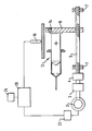
- an infusion pump includes a motor 2 connected through a gearbox 3 and a coupling 4 to a drive screw 5 mounted for rotation in bearings 7.
- a disengagement head 8 is mounted for longitudinal movement along drive screw 5 and at its free end engages an end of a piston 6 forming part of a syringe 12.
- the disengagement head 8 has mounted thereon for movement therewith a permanent magnet 14. Located adjacent the syringe 12 inside the pump case is a reed switch 16. The reed switch 16 is electrically connected to a microprocessor 20 which is also electrically connected to an encoder 22 incorporated in the motor 2.
- the disengagement head 8 In use, when it is desired to expel medical liquid in the syringe 12 and deliver said liquid to a patient the disengagement head 8 is moved to engage the end of the piston 6, the motor 2 is operated thereby driving piston 6 to the left (as shown) into the syringe 12. The disengagement head 8 will cause the piston 6 to expel fluid in the syringe 12 from the left hand end (as shown) thereof at a predetermined rate in a manner known per se . The piston 6 will travel along the interior of the syringe 12 and the permanent magnet 14 mounted on the disengagement head 8 will eventually, as it passes the reed switch 16, close said reed switch (the trigger point).
- the closure of the reed switch 16 generates a signal to the microprocessor 20 causing the microprocessor 20 to begin storing the number of pulses transmitted from the motor encoder 22 into a counter 24.
- the number of pulses to the required near end and end of syringe position is calculated by the pump manufacturer and stored in the microprocessor's memory. These calculated numbers are then continuously compared with the value in the counter 24 once the reed switch 16 is closed until they are the same. At this point an alarm is actuated for near end or end of syringe position depending on the count status.
- the alarm system described is accurate in the measurement of the distance from the trigger point, that is, where the magnet 14 closes the reed switch 16, of better than plus or minus 0.001mm due to the required resolution of any pump speed control system.
- the only weakness of the system is the actual size of the syringe 12 being used with regard to the repeatability of the alarm position between syringes.
- the above described alarm system prevents the pump being turned on and started whilst the reed switch 16 is closed up to the end of the disengagement head stroke, since unless the pump can guarantee the position of the disengagement head 8 when the reed switch 16 closes and the pulse count starts the end position of the syringe plunger cannot be controlled relative to its body.
Landscapes
- Health & Medical Sciences (AREA)
- Vascular Medicine (AREA)
- Engineering & Computer Science (AREA)
- Anesthesiology (AREA)
- Biomedical Technology (AREA)
- Heart & Thoracic Surgery (AREA)
- Hematology (AREA)
- Life Sciences & Earth Sciences (AREA)
- Animal Behavior & Ethology (AREA)
- General Health & Medical Sciences (AREA)
- Public Health (AREA)
- Veterinary Medicine (AREA)
- Infusion, Injection, And Reservoir Apparatuses (AREA)
Applications Claiming Priority (2)
| Application Number | Priority Date | Filing Date | Title |
|---|---|---|---|
| GB8906904 | 1989-03-28 | ||
| GB898906904A GB8906904D0 (en) | 1989-03-28 | 1989-03-28 | Improvements in infusion pumps |
Publications (2)
| Publication Number | Publication Date |
|---|---|
| EP0390388A2 true EP0390388A2 (fr) | 1990-10-03 |
| EP0390388A3 EP0390388A3 (fr) | 1991-09-11 |
Family
ID=10654013
Family Applications (1)
| Application Number | Title | Priority Date | Filing Date |
|---|---|---|---|
| EP19900302913 Withdrawn EP0390388A3 (fr) | 1989-03-28 | 1990-03-19 | Pompe d'infusion |
Country Status (2)
| Country | Link |
|---|---|
| EP (1) | EP0390388A3 (fr) |
| GB (1) | GB8906904D0 (fr) |
Cited By (12)
| Publication number | Priority date | Publication date | Assignee | Title |
|---|---|---|---|---|
| DE4208482C1 (fr) * | 1992-03-17 | 1993-08-05 | B. Braun Melsungen Ag, 3508 Melsungen, De | |
| EP0589328A3 (en) * | 1992-09-23 | 1994-06-22 | Becton Dickinson Co | Syringe pump with graphical display of error conditions |
| EP1287840A1 (fr) * | 2001-08-30 | 2003-03-05 | Japan Servo Co. Ltd. | Dispositif de perfusion de liquide |
| US8251071B2 (en) | 2004-10-13 | 2012-08-28 | Mallinckrodt Llc | Powerhead of a power injection system |
| WO2015124081A1 (fr) * | 2014-02-20 | 2015-08-27 | 江苏多维科技有限公司 | Pompe seringue à injection précise et son procédé de fabrication |
| US10232109B2 (en) | 2014-04-14 | 2019-03-19 | MultiDimension Technology Co., Ltd. | Mini lead screw pump utilizing a magnetoresistive sensor and manufacturing method thereof |
| CN111803755A (zh) * | 2012-12-21 | 2020-10-23 | 德卡产品有限公司 | 注射泵系统 |
| US10898640B2 (en) | 2018-07-11 | 2021-01-26 | Flex, Ltd. | Visual detection for IV pump tube calibration |
| US10905821B2 (en) | 2018-07-11 | 2021-02-02 | Flex, Ltd. | Capacitor detection for IV pump tube calibration |
| US11504469B2 (en) | 2018-07-11 | 2022-11-22 | Flex Ltd. | Reed switch detection for IV pump tube calibration |
| US20220409810A1 (en) * | 2019-11-26 | 2022-12-29 | Nemera La Verpillière | Device For Inserting A Needle |
| CN116724170A (zh) * | 2020-12-21 | 2023-09-08 | 哈立德·阿布萨利赫 | 改进的泵装置 |
Family Cites Families (4)
| Publication number | Priority date | Publication date | Assignee | Title |
|---|---|---|---|---|
| GB2094628A (en) * | 1981-03-10 | 1982-09-22 | Ealing The Corp | Infusion apparatus |
| IT1144743B (it) * | 1981-07-09 | 1986-10-29 | Mario Cane | Apparecchio infusore di insulina perfezionato |
| US4435173A (en) * | 1982-03-05 | 1984-03-06 | Delta Medical Industries | Variable rate syringe pump for insulin delivery |
| DE3851336T2 (de) * | 1988-01-07 | 1995-05-11 | Bernard Hazon | Ambulante vorrichtung und verfahren zum bedienen einer spritze für parenterale infusion mit vom spritzeninhalt abhängigen abgabevolumen. |
-
1989
- 1989-03-28 GB GB898906904A patent/GB8906904D0/en active Pending
-
1990
- 1990-03-19 EP EP19900302913 patent/EP0390388A3/fr not_active Withdrawn
Cited By (20)
| Publication number | Priority date | Publication date | Assignee | Title |
|---|---|---|---|---|
| DE4208482C1 (fr) * | 1992-03-17 | 1993-08-05 | B. Braun Melsungen Ag, 3508 Melsungen, De | |
| EP0561123A1 (fr) * | 1992-03-17 | 1993-09-22 | B. Braun Melsungen AG | Dispositif de perfusion à pression |
| EP0589328A3 (en) * | 1992-09-23 | 1994-06-22 | Becton Dickinson Co | Syringe pump with graphical display of error conditions |
| EP1287840A1 (fr) * | 2001-08-30 | 2003-03-05 | Japan Servo Co. Ltd. | Dispositif de perfusion de liquide |
| US6776773B2 (en) | 2001-08-30 | 2004-08-17 | Japan Servo Co., Ltd. | Liquid infusion apparatus |
| US8366671B2 (en) | 2004-10-13 | 2013-02-05 | Mallinckrodt Llc | Powerhead of a power injection system |
| US8726910B2 (en) | 2004-10-13 | 2014-05-20 | Mallinckrodt Llc | Powerhead of a power injection system |
| US9168335B2 (en) | 2004-10-13 | 2015-10-27 | Mallinckrodt Llc | Powerhead of a power injection system |
| US8251071B2 (en) | 2004-10-13 | 2012-08-28 | Mallinckrodt Llc | Powerhead of a power injection system |
| CN111803755B (zh) * | 2012-12-21 | 2023-08-29 | 德卡产品有限公司 | 注射泵系统 |
| CN111803755A (zh) * | 2012-12-21 | 2020-10-23 | 德卡产品有限公司 | 注射泵系统 |
| WO2015124081A1 (fr) * | 2014-02-20 | 2015-08-27 | 江苏多维科技有限公司 | Pompe seringue à injection précise et son procédé de fabrication |
| US10238793B2 (en) | 2014-02-20 | 2019-03-26 | Multidimension Technology Co., Ltd | Precision syringe pump and manufacturing method thereof |
| US10232109B2 (en) | 2014-04-14 | 2019-03-19 | MultiDimension Technology Co., Ltd. | Mini lead screw pump utilizing a magnetoresistive sensor and manufacturing method thereof |
| US10905821B2 (en) | 2018-07-11 | 2021-02-02 | Flex, Ltd. | Capacitor detection for IV pump tube calibration |
| US11504469B2 (en) | 2018-07-11 | 2022-11-22 | Flex Ltd. | Reed switch detection for IV pump tube calibration |
| US10898640B2 (en) | 2018-07-11 | 2021-01-26 | Flex, Ltd. | Visual detection for IV pump tube calibration |
| US12070573B2 (en) | 2018-07-11 | 2024-08-27 | Flex Ltd. | Visual detection for IV pump tube calibration |
| US20220409810A1 (en) * | 2019-11-26 | 2022-12-29 | Nemera La Verpillière | Device For Inserting A Needle |
| CN116724170A (zh) * | 2020-12-21 | 2023-09-08 | 哈立德·阿布萨利赫 | 改进的泵装置 |
Also Published As
| Publication number | Publication date |
|---|---|
| GB8906904D0 (en) | 1989-05-10 |
| EP0390388A3 (fr) | 1991-09-11 |
Similar Documents
| Publication | Publication Date | Title |
|---|---|---|
| US6854620B2 (en) | Drive system for an infusion pump | |
| US4952205A (en) | Pressure infusion device | |
| JP2638632B2 (ja) | 非経口的な注射のために注射器の内容量によって流出量をサーボ制御する救急用注射器押し部材装置 | |
| US4695271A (en) | Angiographic injector | |
| US4544369A (en) | Battery operated miniature syringe infusion pump | |
| CA2259442C (fr) | Dispositif d'injection et procede de fonctionnement dudit dispositif | |
| EP2384207B1 (fr) | Dispositif d'injection médical avec contrôle de moteur électrique | |
| CN1217710C (zh) | 一种注射器泵 | |
| US6726661B2 (en) | Air shot mechanism for electronic injection devices | |
| JP4149657B2 (ja) | 自動化送出装置 | |
| US4396385A (en) | Flow metering apparatus for a fluid infusion system | |
| US4919650A (en) | Infusion pump | |
| US6565535B2 (en) | Medical infusion and aspiration system | |
| US5383858B1 (en) | Front-loading medical injector and syringe for use therewith | |
| JP2006500087A5 (fr) | ||
| CA2494553A1 (fr) | Injecteur | |
| DK2482994T3 (en) | fluid delivery system | |
| NO315455B1 (no) | Anordning ved elektronisk styrte injeksjonsanordninger | |
| CA2700289A1 (fr) | Dispositif de detection de positions et procede pour detecter au moins deux positions | |
| CN114191647B (zh) | 多泵串联输注的控制方法及多泵串联输注系统 | |
| HUP0102219A2 (hu) | Infúziós pumpa és eljárás folyadék intravaszkuláris infúziójához | |
| EP0390388A3 (fr) | Pompe d'infusion | |
| CS264858B1 (cs) | Lineární dávkovač | |
| CA3247820A1 (fr) | Système de dosage | |
| HK1240870B (zh) | 给药液装置 |
Legal Events
| Date | Code | Title | Description |
|---|---|---|---|
| PUAI | Public reference made under article 153(3) epc to a published international application that has entered the european phase |
Free format text: ORIGINAL CODE: 0009012 |
|
| AK | Designated contracting states |
Kind code of ref document: A2 Designated state(s): BE DE FR GB IT NL SE |
|
| PUAL | Search report despatched |
Free format text: ORIGINAL CODE: 0009013 |
|
| AK | Designated contracting states |
Kind code of ref document: A3 Designated state(s): BE DE FR GB IT NL SE |
|
| STAA | Information on the status of an ep patent application or granted ep patent |
Free format text: STATUS: THE APPLICATION IS DEEMED TO BE WITHDRAWN |
|
| 18D | Application deemed to be withdrawn |
Effective date: 19920312 |