EP0390534A2 - Laserstrahlenablenkungsgerät - Google Patents
Laserstrahlenablenkungsgerät Download PDFInfo
- Publication number
- EP0390534A2 EP0390534A2 EP90303311A EP90303311A EP0390534A2 EP 0390534 A2 EP0390534 A2 EP 0390534A2 EP 90303311 A EP90303311 A EP 90303311A EP 90303311 A EP90303311 A EP 90303311A EP 0390534 A2 EP0390534 A2 EP 0390534A2
- Authority
- EP
- European Patent Office
- Prior art keywords
- laser beam
- polygonal mirror
- mirror
- incident
- deflection
- Prior art date
- Legal status (The legal status is an assumption and is not a legal conclusion. Google has not performed a legal analysis and makes no representation as to the accuracy of the status listed.)
- Granted
Links
Images


Classifications
-
- H—ELECTRICITY
- H01—ELECTRIC ELEMENTS
- H01S—DEVICES USING THE PROCESS OF LIGHT AMPLIFICATION BY STIMULATED EMISSION OF RADIATION [LASER] TO AMPLIFY OR GENERATE LIGHT; DEVICES USING STIMULATED EMISSION OF ELECTROMAGNETIC RADIATION IN WAVE RANGES OTHER THAN OPTICAL
- H01S3/00—Lasers, i.e. devices using stimulated emission of electromagnetic radiation in the infrared, visible or ultraviolet wave range
-
- H—ELECTRICITY
- H04—ELECTRIC COMMUNICATION TECHNIQUE
- H04N—PICTORIAL COMMUNICATION, e.g. TELEVISION
- H04N3/00—Scanning details of television systems; Combination thereof with generation of supply voltages
- H04N3/02—Scanning details of television systems; Combination thereof with generation of supply voltages by optical-mechanical means only
- H04N3/08—Scanning details of television systems; Combination thereof with generation of supply voltages by optical-mechanical means only having a moving reflector
-
- G—PHYSICS
- G02—OPTICS
- G02B—OPTICAL ELEMENTS, SYSTEMS OR APPARATUS
- G02B26/00—Optical devices or arrangements for the control of light using movable or deformable optical elements
- G02B26/08—Optical devices or arrangements for the control of light using movable or deformable optical elements for controlling the direction of light
- G02B26/10—Scanning systems
- G02B26/12—Scanning systems using multifaceted mirrors
- G02B26/129—Systems in which the scanning light beam is repeatedly reflected from the polygonal mirror
Definitions
- This invention relates to a laser beam deflection apparatus.
- Figure 1 shows the overall arrangement of a video display apparatus of the projection type, disclosed in Japanese Laid-Open Utility Model Gazette No. 56-152456 and The Journal of the Institute of Television Engineers of Japan, Vol. 29, No. 2, 1975.
- laser light sources 1a and lb which might be semiconductor lasers or gas lasers.
- a read laser beam from the laser light source 1a enters an optical modulator 2a.
- a green laser beam and a blue laser beam from the laser light source lb fall on a dichroic mirror 3a, where they are separated to provide a green laser beam and a blue laser beam.
- the green laser beam enters an optical modulator 2b, whereas the blue laser beam passes through a reflection prism 4a to an optical modulator 2c.
- Modulation signals corresponding to three primary colour signals, provided as a video signal of an image to be displayed, are supplied to the optical modulators 2a, 2b and 2c, respectively.
- the optical modulators 2a, 2b and 2c modulate the luminous intensity or the red, green and blue laser beams on the basis of the modulation signals.
- the laser beams from the optical modulators 2a, 2b and 3c are supplied to lenses 5a, 5b and 5c for adjusting the diameters of the respective laser beams.
- the blue laser beam from the lens 5c passes to a dichroic mirror 3b through a reflection prism 4b, and the green laser beam from the lens 5b falls on the other mirror face of the dichroic mirror 3b, whereby the blue and green laser beams are mixed.
- the mixed laser beam falls on a dichroic mirror 3c, and the red laser beam from the lens 5a falls on the other mirror face of the dichroic mirror 3c, whereby a mixed laser beam of three primary colours is obtained.
- the modulated, mixed laser beam is supplied to a reflection portion 11 of a rotating polygonal mirror 10.
- a reflecting portion 11 is formed by arranging a plurality of flat mirrors with an equal spacing in an annular fashion. This annular-shaped reflecting portion 11 is rotated at high speed by some suitable drive means such as a motor.
- the flat mirrors forming the reflecting portion 11 may be a regular icosipentahedron thereby to deflect a laser beam incident on each flat mirror.
- Figures 2A and 2B illustrate the deflected states of the laser beam.
- an angle ⁇ 2 formed by the laser beams l out and l out ′ becomes the deflection angle of the flat mirror 111, that is the angle through which the laser beam is scanned as the reflecting portion 11 is rotated. This constitutes one "deflection cycle" of the rotating reflection portion 11.
- Other flat mirrors of the reflecting portion 11 deflect the laser beams by a similar deflection angle so that, when the reflecting portion 11 is composed of 25 flat mirrors, the laser beam is deflected through the angle ⁇ 2, 25 times per revolution of the reflecting portion 11.
- the laser beam reflected by the polygonal mirror 10 passes through a projection lens 6 to a galvano mirror 7 which is controlled in rotation by a drive source 7a.
- the galvano mirror 7 is rotated during a predetermined interval by the drive source 7a, the laser beam from the polygonal mirror 10 is deflected through a predetermined deflection angle over a predetermined interval.
- the deflection direction of the polygonal mirror 10 and the deflection direction by the galvano mirror 7 are selected to be at right angles to each other.
- the deflection by the polygonal mirror 10 corresponds to the horizontal deflection in the television receiver
- the deflection by the galvano mirror 7 corresponds to the vertical deflection in the television receiver.
- a laser beam reflected by the galvano mirror 7 is reflected by a reflection mirror 8 and is made incident on the rear surface of a flat screen 9.
- the viewer can see an image, formed by the scanning laser beams, from the front surface side of the screen 9.
- Horizontal and vertical scanning cycles of the video signal for forming the modulation signals supplied to the optical modulators 2a, 2b and 2c are synchronised with the deflection cycle of the polygonal mirror 10 and the deflection cycle of the galvano mirror 7, whereby an image based on the video signal is displayed on the screen 9 by the raster-scanning of the laser beams. Therefore, an image of one field-time is displayed on the screen 9 during one field period of the video signal.
- the display apparatus of Figure 1 is operated as a projection-type video display apparatus.
- the polygonal mirror 10 having 25 flat mirrors must be rotated at 81000 rpm, which needs a special drive motor and a special bearing for effecting such high speed rotation. If the polygonal mirror 10 is rotated at such high speed, then the flat mirrors of the polygonal mirror will be moving faster than the velocity of sound, which is not desirable from a safety standpoint.
- each flat mirror is formed on each plane of a polygonal mirror having pentacontane reflection faces and a diameter of 40 cm, the width of each flat mirror becomes 2.5 cm.
- a laser beam having a spot diameter of 1 mm becomes incident on the polygonal mirror, if the laser beam becomes incident on both planes at the boundary portion of the two flat mirrors, then a so-called eclipse will occur.
- This eclipse makes respective end portions of each plane become invalid by 1 mm each, making 40% of each plane invalid. Therefore, only 60% of the plane can be effectively utilised, and hence the deflection angle becomes very small, which is not advantageous in practice.
- the beam diameter of the laser beam is reduced, then the resolution of the image to be displayed will be degraded. Accordingly, it is not possible to reduce the invalid period by reducing the beam diameter of the laser beam.
- a laser beam deflection apparatus including: a rotatable polygonal mirror having a plurality of reflection surfaces; and means for directing a laser beam to be incident on each of said reflection surfaces in turn as the polygonal mirror rotates, so that the laser beam is deflected through a predetermined angle during a predetermined increment of rotation (deflection cycle) of the polygonal mirror; wherein: n reflection means are positioned in facing relation to the polygonal mirror, where n is an integer, and are aligned in the rotational direction of the polygonal mirror for reflecting the laser beam reflected from one of said reflection surfaces back towards said reflection surfaces, whereby the laser beam is twice reflected by said reflection surfaces and is deflected through the predetermined angle n times for each said deflection cycle of the polygonal mirror.
- FIG. 3 shows the main components of the laser beam deflection apparatus, and the other portions are constructed similarly to those of Figure 1.
- the rotating polygonal mirror 10 comprises a reflecting portion 11 and a driving motor 12.
- the reflecting portion 11 is formed by arranging a regular tetracosane or 24 flat mirrors 111, 112, ... 1124 with an equal spacing in an annular fashion.
- the reflecting portion 11 is rotated in the direction indicated by the arrow in Figure 4 by the driving motor 12.
- a laser beam 11, modulated in intensity, is made incident on each of the respective flat mirrors 111 to 1124, in turn, from a direction slightly lower than the reflecting portion 11, and in a direction towards the rotational centre of the polygonal mirror 10.
- a reflected laser beam 12 which is the incident laser beam l1 reflected on the reflecting portion 11, is deflected through a deflection angle by each one of the flat mirrors 111, 112, ..., 1124 in accordance with the rotation of the reflecting portion 11.
- the point at which the laser beam becomes incident on the reflecting portion 11 assumes a primary incident point l a .
- Two flat mirrors 21 and 22 are located at the position to which the reflected laser beam l2 reaches.
- the respective flat mirrors 21 and 22 are located such that, as the reflecting portion 11 rotates in the direction indicated, if the deflected range of the reflected laser beam l2 is divided by one-half then the reflected laser beam l2 within one deflected range (one horizontal scan line) becomes incident on the flat mirror 21, whereas the reflected laser beam l1 within the other deflected range (the next horizontal scan line) becomes incident on the other flat mirror 22.
- the reflecting portion 11 of the polygonal mirror 10 is formed of the 24 flat mirrors 111 to 1124 as described above, so that the angle through which the reflected laser beam 12 is deflected at each of the flat mirrors 111, 112,..., 1124 becomes 30 o .
- the reflected laser beam l2 in the first deflection range of 15 o is incident on the flat mirror 21, and the reflected laser beam l2 in the remaining range of 15 o is incident on the other flat mirror 22.
- the mirrors are so arranged that normal lines extended perpendicularly from the centre (incident point provided when the deflection angle is 7.5 o ) of each of the reflecting surfaces of the flat mirrors 21 and 22 are convergent at the spot l b vertically aligned with the primary incident point l a .
- the respective flat mirrors 21 and 22 are located such that, when the incident laser beam l2, which is deflected through the range of 15 o at each of the flat mirrors 21 and 22 is deflected at the intermediate deflection angle of 7.5 o from the start of incidence, the secondary incident point l b at which the reflected laser beam l3 again falls on the reflecting portion 11 of the polygonal mirror 10 is vertically aligned with the primary incident point l a as seen from the top of the polygonal mirror 10 (state of Figure 4).
- a reflected laser beam l4 reflected at the secondary incident point l b of the reflecting portion 11 on the basis of the laser beam l3 travels above the flat mirrors 21 and 22 and reaches the projection lens (see Figures 1 and 3).
- the reflecting portion 11 of the polygonal mirror 10 is formed of the 24 flat mirrors 111 to 1124 so that when the reflecting portion 11 is rotated by 15 o , the reflecting portion 11 is moved by the width of one of the flat mirrors 111 to 1124. Accordingly, the laser beam l2 reflected during the rotation of 15 o is deflected from the maximum minus direction of 15 o towards the extreme plus direction of 15 o . Therefore, the laser beam l2 is deflected through a deflection angle of a total of 30 o by one of the flat mirrors 111 to 1124.
- the flat mirrors 21 and 22 are provided, so that the laser beam falls on the polygonal mirror 10 one more time, with a different incident angle. Consequently, the laser beam l4 finally reflected from the reflecting portion 11 is deflected towards the ⁇ directions by 15 o each, that is, for a total of 30 o when the reflecting portion 11 is rotated by only 7,5 o . Therefore, when the reflecting portion 11 is rotated by a full rotational angle of 15 o corresponding to the width of one of the flat mirrors 111 to 1124, the laser beam is deflected twice, through the deflection angle of 30 o .
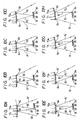
- FIGS 5A to 5H illustrate the changes occurring when the laser beam l1 is incident, for example, on the flat mirror 111 of the reflecting portion 11 during one deflection cycle.
- the primary incident point l a of the laser beam l1 is located at one end portion of the flat mirror 111
- the reflected laser beam l2 is deflected towards the minus direction
- the reflected laser beam l2 is incident on the outer portion of the flat mirror 21.
- the secondary incident point l b of the reflected laser beam l3 from the flat mirror 21 is located at substantially the central portion of the flat mirror 111.
- the reflected laser beam l4 from the secondary incident point l b is deflected towards the minus direction substantially parallel to the light path of the laser beam l2.
- the reflected laser beam l4 is sequentially deflected towards the plus direction in accordance with the movement of the flat mirror 111 due to the rotation of the polygonal mirror 10 as shown in Figures 5B to 5D.
- the primary incident point l a on the flat mirror 111 is located at about the central portion of the flat mirror 111 (that is, when the deflection angle of the laser beam l2 becomes approximately 7.5 o ) the deflection angle of the reflected laser beam l4 towards the plus direction is a maximum and the angle formed by the laser beam l2 and the laser beam l4 becomes about 15 o .
- Figures 6A and 6B illustrate the conditions that the primary incident point l a and the secondary incident point l b on the flat mirror 111 of the polygonal mirror 10 are constantly changed.
- Figure 6A shows the incident points where the flat mirror 111 is fixed at a constant position
- Figure 6B shows incident points where the primary incident point l a fixed at a constant position.
- an open circle represents the primary incident point l a
- a cross mark represents the secondary incident point l b .
- the states of the flat mirror 111 as shown by reference letters a to h indicate incident points corresponding to the incident states of Figures 5A to 5H, respectively.
- the secondary incident point l b is changed under the condition that it is divided by one-half. It is thus to be understood that the deflection at the same deflection angle and in the same deflection range is performed twice by the single flat mirror 111.
- the rotational speed of the polygonal mirror 10 is selected to be the same as that of the previous proposed apparatus, the number of flat mirrors can be reduced, whereby the diameter of the reflecting portion 11 of the polygonal mirror 10 can be reduced or the width of each of the flat mirrors 111 to 1124 can be increased.
- a second embodiment of laser beam deflection apparatus according to the present invention will be described with reference to Figures 7 to 10.
- the laser beam deflection apparatus is applied to a video laser display apparatus.
- a laser beam is deflected four times, each time the flat mirrors 111 to 1124 of the polygonal mirror 10 are rotated by the same amount.
- a laser beam l1′ modulated in intensity, falls on an incident point l a ′ of each of the flat mirrors 111 to 1124 of the reflecting portion 11 with a very small upward inclination angle.
- four flat mirrors 31, 32, 33 and 34 are located at the positions to which the reflected laser beam l2′, which is the incident laser beam l1′ reflected by the reflecting portion 11, reaches.
- the flat mirrors 31, 32, 33 and 34 are located such that, when the deflection range of the reflected laser beam l2′ is divided equally by four, the reflected laser beam l2′ within the deflection range nearest to the minus direction is incident on the first flat mirror 31, the reflected laser beam l2′ within the adjacent deflection range is incident on the second flat mirror 32, the reflected laser beam l2′ within the adjacent deflection range is incident on the third flat mirror 33, and the reflected laser beam l2′ within the deflection range nearest to the plus direction is incident on the fourth flat mirror 34.
- the reflecting portion 11 of the polygonal mirror 10 is formed of the 24 flat mirrors 111 to 1124, so that the angle through which the reflected laser beam l2′ is deflected at each of the flat mirrors 111 to 1124 becomes 30 o.
- the reflected laser beam l2′ falls on a different flat mirror 31 to 34 at every 7.5 o of rotation.
- a reflected laser beam l3′ of the laser beam l2′ incident on each of the flat mirrors 31 to 34 is made incident on the reflecting portion 11 of the polygonal mirror 10 one more time.
- the point at which the laser beam l3′ is incident on the reflecting portion 11 is assumed to be a secondary incident point l b .
- the flat mirrors 31 to 34 are located such that, when the incident laser beam l2′ is deflected in the deflection range of 7.5 o , and each of the flat mirrors 31 to 34 is given an intermediate deflection angle of 3.75 o from the start of incidence, the secondary incident point l b ′ at which the reflected laser beam l3′ is again incident on the reflecting portion 11 of the polygonal mirror 10 is vertically aligned with the primary incident point l a ′ that is when the polygonal mirror 10 is viewed from above.
- a laser beam l4′ reflected from the secondary incident point l b ′ of the reflecting portion 11 of the polygonal mirror 10 on the basis of the laser beam l2′ travels above the flat mirrors 31 to 34, and is supplied to the projection lens (see Figure 1).
- each deflection angle is reduced to one-half of that of the first embodiment, that is, 15 o .
- Figures 8A to 8H show the deflected conditions of the laser beams.
- the reflected laser beam l4′ is sequentially deflected towards the plus direction as shown in Figure 8B. This completes one sweep of the laser beam l4′.
- Figures 9A and 98 illustrate the conditions that the primary incident point l a ′ and the secondary incident point l b ′ on the flat mirror 111 of the polygonal mirror 10 are changed at constant times.
- Figure 9A shows incident points where the flat mirror 111 is fixed at a constant position
- Figure 9B shows incident points where the primary incident point l a ′ is fixed at a constant position.
- an open circle represents the primary incident point l a ′
- a cross mark represents the secondary incident point l b ′.
- the secondary incident point l b ′ is changed under the condition that it is divided equally by four.
- the laser beam is deflected four times through the same deflection angle and in the same deflection range by one flat mirror 111.
- the secondary incident point l b ′ falls within the same range shown by a one-dot chain line.
- the number of deflections is increased by four times, so that the rotational speed of the polygonal mirror 10 can be decreased and that the number of mirror surfaces of the polygonal mirror 10 can be decreased.
- the total of four deflection angles at which the laser beams are deflected in the flat mirrors 111 to 1124 of the polygonal mirror 10 is 60 o similarly to the embodiment of Figure 3. Accordingly, one deflection angle becomes 15 o , which is one-half of that of the embodiment of Figure 3.
- the laser beams l1 and l1′ incident on the polygonal mirror 10 are made incident in the rotation centre direction of the polygonal mirror 10 in the above-described embodiment, the laser beam l1 ⁇ may become incident on the polygonal mirror 10 with a small inclination angle in the lateral direction as shown in Figures 10A to 10H.
- the reflected laser beam l4 ⁇ from the secondary incident point l b ⁇ is deflected in accordance with the rotation of the polygonal mirror 10 similarly to the second embodiment of Figure 7. Moreover, the deflection direction of the reflected laser beam l4 ⁇ can be changed from that of the second embodiment of Figure 7.
- the laser beam deflection apparatus can be applied to various apparatuses in which a laser beam is deflected by a polygonal mirror.
- the invention can be applied to a so-called laser printer in which a laser beam, modulated in intensity on the basis of a visual image to be displayed, is deflected by a polygonal mirror and is irradiated on a developing drum.
Landscapes
- Physics & Mathematics (AREA)
- Optics & Photonics (AREA)
- Engineering & Computer Science (AREA)
- General Physics & Mathematics (AREA)
- Multimedia (AREA)
- Signal Processing (AREA)
- Electromagnetism (AREA)
- Plasma & Fusion (AREA)
- Mechanical Optical Scanning Systems (AREA)
- Lasers (AREA)
- Facsimile Scanning Arrangements (AREA)
- Optical Elements Other Than Lenses (AREA)
Applications Claiming Priority (2)
| Application Number | Priority Date | Filing Date | Title |
|---|---|---|---|
| JP1079944A JPH02259617A (ja) | 1989-03-30 | 1989-03-30 | レーザビーム偏向装置 |
| JP79944/89 | 1989-03-30 |
Publications (3)
| Publication Number | Publication Date |
|---|---|
| EP0390534A2 true EP0390534A2 (de) | 1990-10-03 |
| EP0390534A3 EP0390534A3 (de) | 1992-03-18 |
| EP0390534B1 EP0390534B1 (de) | 1996-01-10 |
Family
ID=13704421
Family Applications (1)
| Application Number | Title | Priority Date | Filing Date |
|---|---|---|---|
| EP90303311A Expired - Lifetime EP0390534B1 (de) | 1989-03-30 | 1990-03-28 | Laserstrahlenablenkungsgerät |
Country Status (5)
| Country | Link |
|---|---|
| US (1) | US5044710A (de) |
| EP (1) | EP0390534B1 (de) |
| JP (1) | JPH02259617A (de) |
| KR (1) | KR900015396A (de) |
| DE (1) | DE69024690T2 (de) |
Families Citing this family (22)
| Publication number | Priority date | Publication date | Assignee | Title |
|---|---|---|---|---|
| US5187606A (en) * | 1989-10-20 | 1993-02-16 | Canon Kabushiki Kaisha | Scanning optical apparatus |
| US5184246A (en) * | 1991-02-25 | 1993-02-02 | Nira Schwartz | Scanning of moving objects using unique polygon mounted on carousel which rotates at twice polygon's speed |
| US5387996A (en) * | 1992-07-20 | 1995-02-07 | Hughes Aircraft Company | Method of obtaining a narrow field of view scan |
| JP2830670B2 (ja) * | 1992-12-29 | 1998-12-02 | キヤノン株式会社 | 光走査装置 |
| DE10062841B4 (de) * | 2000-12-15 | 2009-04-16 | Hilti Aktiengesellschaft | Lichtstrahlenempfänger für Laserpositioniergeräte |
| ES2310744T3 (es) * | 2003-06-06 | 2009-01-16 | The General Hospital Corporation | Fuente de luz sintonizable en longitudes de onda. |
| KR20060112664A (ko) * | 2003-12-10 | 2006-11-01 | 마츠시타 덴끼 산교 가부시키가이샤 | 디스플레이 장치 및 그 주사 방법 |
| US10426548B2 (en) | 2006-02-01 | 2019-10-01 | The General Hosppital Corporation | Methods and systems for providing electromagnetic radiation to at least one portion of a sample using conformal laser therapy procedures |
| EP3150110B1 (de) | 2006-05-10 | 2020-09-02 | The General Hospital Corporation | Verfahren, anordnungen und systeme zur bereitstellung von frequenzbereichsabbildung einer probe |
| WO2008049118A2 (en) | 2006-10-19 | 2008-04-24 | The General Hospital Corporation | Apparatus and method for obtaining and providing imaging information associated with at least one portion of a sample and effecting such portion(s) |
| EP2602651A3 (de) * | 2007-03-23 | 2014-08-27 | The General Hospital Corporation | Verfahren, Anordnungen und Vorrichtung zur Verwendung eines wellenlängengewobbelten Lasers anhand von Winkelabtastungs- und Dispersionsverfahren |
| JP2009212273A (ja) * | 2008-03-04 | 2009-09-17 | Sun Tec Kk | 波長走査型レーザ光源 |
| WO2010009136A2 (en) | 2008-07-14 | 2010-01-21 | The General Hospital Corporation | Apparatus and methods for color endoscopy |
| EP2542145B1 (de) | 2010-03-05 | 2020-08-12 | The General Hospital Corporation | Systeme zur bereitstellung mikroskopischer bilder von mindestens einer anatomischen struktur mit einer bestimmten auflösung |
| US9968261B2 (en) | 2013-01-28 | 2018-05-15 | The General Hospital Corporation | Apparatus and method for providing diffuse spectroscopy co-registered with optical frequency domain imaging |
| WO2014121082A1 (en) | 2013-02-01 | 2014-08-07 | The General Hospital Corporation | Objective lens arrangement for confocal endomicroscopy |
| WO2014144709A2 (en) | 2013-03-15 | 2014-09-18 | The General Hospital Corporation | Methods and systems for characterizing an object |
| WO2015009932A1 (en) | 2013-07-19 | 2015-01-22 | The General Hospital Corporation | Imaging apparatus and method which utilizes multidirectional field of view endoscopy |
| WO2015013651A2 (en) | 2013-07-26 | 2015-01-29 | The General Hospital Corporation | System, apparatus and method utilizing optical dispersion for fourier-domain optical coherence tomography |
| WO2015105870A1 (en) | 2014-01-08 | 2015-07-16 | The General Hospital Corporation | Method and apparatus for microscopic imaging |
| US10736494B2 (en) | 2014-01-31 | 2020-08-11 | The General Hospital Corporation | System and method for facilitating manual and/or automatic volumetric imaging with real-time tension or force feedback using a tethered imaging device |
| US10228556B2 (en) | 2014-04-04 | 2019-03-12 | The General Hospital Corporation | Apparatus and method for controlling propagation and/or transmission of electromagnetic radiation in flexible waveguide(s) |
Family Cites Families (7)
| Publication number | Priority date | Publication date | Assignee | Title |
|---|---|---|---|---|
| GB448238A (en) * | 1934-12-03 | 1936-06-03 | Ernest Traub | Improvements in scanning devices for television apparatus |
| US2163548A (en) * | 1936-07-16 | 1939-06-20 | Kolorama Lab Inc | System for television scanning |
| US3813140A (en) * | 1971-12-13 | 1974-05-28 | Bendix Corp | Rotating prism scanning system having range compensation |
| US3972583A (en) * | 1972-01-25 | 1976-08-03 | Redifon Limited | Scanning devices |
| GB1544097A (en) * | 1976-07-22 | 1979-04-11 | Redifon Flight Simulation Ltd | Laser systems |
| US4429948A (en) * | 1981-05-14 | 1984-02-07 | International Business Machines Corporation | Optical alignment compensation |
| GB2207576A (en) * | 1987-07-22 | 1989-02-01 | Antony John Clynick | Optical-mechanical scan rate multiplier |
-
1989
- 1989-03-30 JP JP1079944A patent/JPH02259617A/ja active Pending
-
1990
- 1990-03-26 US US07/498,948 patent/US5044710A/en not_active Expired - Fee Related
- 1990-03-28 EP EP90303311A patent/EP0390534B1/de not_active Expired - Lifetime
- 1990-03-28 DE DE69024690T patent/DE69024690T2/de not_active Expired - Fee Related
- 1990-03-28 KR KR1019900004146A patent/KR900015396A/ko not_active Abandoned
Also Published As
| Publication number | Publication date |
|---|---|
| US5044710A (en) | 1991-09-03 |
| DE69024690T2 (de) | 1996-06-05 |
| DE69024690D1 (de) | 1996-02-22 |
| KR900015396A (ko) | 1990-10-26 |
| EP0390534A3 (de) | 1992-03-18 |
| EP0390534B1 (de) | 1996-01-10 |
| JPH02259617A (ja) | 1990-10-22 |
Similar Documents
| Publication | Publication Date | Title |
|---|---|---|
| EP0390534B1 (de) | Laserstrahlenablenkungsgerät | |
| US6020937A (en) | High resolution digital projection TV with dynamically adjustable resolution utilizing a system of rotating mirrors | |
| US5402184A (en) | Projection system having image oscillation | |
| US7252391B2 (en) | Method of producing an image | |
| EP0084434B1 (de) | Licht-Projektionsapparat | |
| KR100389865B1 (ko) | 마이크로미러 디바이스 및 이를 채용한 프로젝터 | |
| US5148285A (en) | Image display apparatus with increased raster scan rate of laser beams | |
| US5319490A (en) | Helmet mounted display including synchronously moving tilted mechanisms | |
| US7118226B2 (en) | Sequential color recapture for image display systems | |
| KR100607644B1 (ko) | 2차원 광주사 장치 및 이를 이용하는 영상 표시 장치 | |
| US4230394A (en) | Mirror facet tracker using spherical mirrors | |
| US7075562B2 (en) | Optical scanning device | |
| RU2030842C1 (ru) | Устройство для воспроизведения на экране изображения | |
| KR100486707B1 (ko) | 가동 미러 장치 및 이를 채용한 프로젝터 | |
| US12574481B2 (en) | Digital display system and method | |
| JPH0368914A (ja) | レーザディスプレイ装置 | |
| KR100607643B1 (ko) | 2차원 광주사 장치 및 이를 이용하는 영상 표시 장치 | |
| JPH02167522A (ja) | レーザビーム偏向装置 | |
| JP2796684B2 (ja) | レーザ表示装置 | |
| JPH0397364A (ja) | 画像走査記録装置 | |
| US6067127A (en) | Method and apparatus for reducing the rotation rate of mirrors in a high resolution digital projection display | |
| JP2788770B2 (ja) | レーザ表示装置 | |
| JPH0381722A (ja) | レーザディスプレイ装置 | |
| JPH08286147A (ja) | レーザポインタ | |
| KR970008405B1 (ko) | 광분리기 |
Legal Events
| Date | Code | Title | Description |
|---|---|---|---|
| PUAI | Public reference made under article 153(3) epc to a published international application that has entered the european phase |
Free format text: ORIGINAL CODE: 0009012 |
|
| AK | Designated contracting states |
Kind code of ref document: A2 Designated state(s): DE FR GB |
|
| PUAL | Search report despatched |
Free format text: ORIGINAL CODE: 0009013 |
|
| AK | Designated contracting states |
Kind code of ref document: A3 Designated state(s): DE FR GB |
|
| 17P | Request for examination filed |
Effective date: 19920730 |
|
| 17Q | First examination report despatched |
Effective date: 19940726 |
|
| GRAA | (expected) grant |
Free format text: ORIGINAL CODE: 0009210 |
|
| AK | Designated contracting states |
Kind code of ref document: B1 Designated state(s): DE FR GB |
|
| REF | Corresponds to: |
Ref document number: 69024690 Country of ref document: DE Date of ref document: 19960222 |
|
| ET | Fr: translation filed | ||
| PLBE | No opposition filed within time limit |
Free format text: ORIGINAL CODE: 0009261 |
|
| STAA | Information on the status of an ep patent application or granted ep patent |
Free format text: STATUS: NO OPPOSITION FILED WITHIN TIME LIMIT |
|
| 26N | No opposition filed | ||
| PGFP | Annual fee paid to national office [announced via postgrant information from national office to epo] |
Ref country code: FR Payment date: 19970313 Year of fee payment: 8 |
|
| PGFP | Annual fee paid to national office [announced via postgrant information from national office to epo] |
Ref country code: GB Payment date: 19970319 Year of fee payment: 8 |
|
| PG25 | Lapsed in a contracting state [announced via postgrant information from national office to epo] |
Ref country code: GB Free format text: LAPSE BECAUSE OF NON-PAYMENT OF DUE FEES Effective date: 19980328 |
|
| PG25 | Lapsed in a contracting state [announced via postgrant information from national office to epo] |
Ref country code: FR Free format text: THE PATENT HAS BEEN ANNULLED BY A DECISION OF A NATIONAL AUTHORITY Effective date: 19980331 |
|
| GBPC | Gb: european patent ceased through non-payment of renewal fee |
Effective date: 19980328 |
|
| REG | Reference to a national code |
Ref country code: FR Ref legal event code: ST |
|
| PGFP | Annual fee paid to national office [announced via postgrant information from national office to epo] |
Ref country code: DE Payment date: 19991231 Year of fee payment: 11 |
|
| PG25 | Lapsed in a contracting state [announced via postgrant information from national office to epo] |
Ref country code: DE Free format text: LAPSE BECAUSE OF NON-PAYMENT OF DUE FEES Effective date: 20020101 |