EP0390660A1 - Verfahren und Einrichtung zur temporalen Interpolation von Bildern mit korrigierter Bewegungskompensation - Google Patents
Verfahren und Einrichtung zur temporalen Interpolation von Bildern mit korrigierter Bewegungskompensation Download PDFInfo
- Publication number
- EP0390660A1 EP0390660A1 EP90400809A EP90400809A EP0390660A1 EP 0390660 A1 EP0390660 A1 EP 0390660A1 EP 90400809 A EP90400809 A EP 90400809A EP 90400809 A EP90400809 A EP 90400809A EP 0390660 A1 EP0390660 A1 EP 0390660A1
- Authority
- EP
- European Patent Office
- Prior art keywords
- motion
- image
- interpolation
- defective
- points
- Prior art date
- Legal status (The legal status is an assumption and is not a legal conclusion. Google has not performed a legal analysis and makes no representation as to the accuracy of the status listed.)
- Granted
Links
- 238000000034 method Methods 0.000 title claims abstract description 40
- 230000002123 temporal effect Effects 0.000 title claims abstract description 22
- 230000002950 deficient Effects 0.000 claims abstract description 38
- 238000004458 analytical method Methods 0.000 claims abstract description 21
- 230000007547 defect Effects 0.000 claims abstract description 15
- 230000007704 transition Effects 0.000 claims abstract description 3
- 239000013598 vector Substances 0.000 claims description 68
- 239000011159 matrix material Substances 0.000 claims description 21
- 238000001914 filtration Methods 0.000 claims description 18
- 238000001514 detection method Methods 0.000 claims description 13
- 230000003628 erosive effect Effects 0.000 claims description 12
- 238000002156 mixing Methods 0.000 claims description 3
- 235000019557 luminance Nutrition 0.000 claims 8
- 238000006243 chemical reaction Methods 0.000 abstract description 3
- 238000010586 diagram Methods 0.000 description 7
- 230000008034 disappearance Effects 0.000 description 4
- 230000000694 effects Effects 0.000 description 4
- 238000012545 processing Methods 0.000 description 4
- 238000006073 displacement reaction Methods 0.000 description 3
- 238000011282 treatment Methods 0.000 description 3
- 238000012935 Averaging Methods 0.000 description 2
- 238000004364 calculation method Methods 0.000 description 2
- 238000012360 testing method Methods 0.000 description 2
- 238000013519 translation Methods 0.000 description 2
- 238000007796 conventional method Methods 0.000 description 1
- 238000012217 deletion Methods 0.000 description 1
- 230000037430 deletion Effects 0.000 description 1
- 235000021183 entrée Nutrition 0.000 description 1
- 238000009432 framing Methods 0.000 description 1
- 238000000265 homogenisation Methods 0.000 description 1
- 230000000873 masking effect Effects 0.000 description 1
- 239000000203 mixture Substances 0.000 description 1
- 238000005070 sampling Methods 0.000 description 1
- 230000035945 sensitivity Effects 0.000 description 1
- 230000003595 spectral effect Effects 0.000 description 1
- 238000001228 spectrum Methods 0.000 description 1
- 238000012546 transfer Methods 0.000 description 1
- 230000000007 visual effect Effects 0.000 description 1
Images


Classifications
-
- H—ELECTRICITY
- H04—ELECTRIC COMMUNICATION TECHNIQUE
- H04N—PICTORIAL COMMUNICATION, e.g. TELEVISION
- H04N5/00—Details of television systems
- H04N5/44—Receiver circuitry for the reception of television signals according to analogue transmission standards
- H04N5/46—Receiver circuitry for the reception of television signals according to analogue transmission standards for receiving on more than one standard at will
-
- H—ELECTRICITY
- H04—ELECTRIC COMMUNICATION TECHNIQUE
- H04N—PICTORIAL COMMUNICATION, e.g. TELEVISION
- H04N7/00—Television systems
- H04N7/01—Conversion of standards, e.g. involving analogue television standards or digital television standards processed at pixel level
- H04N7/0135—Conversion of standards, e.g. involving analogue television standards or digital television standards processed at pixel level involving interpolation processes
- H04N7/014—Conversion of standards, e.g. involving analogue television standards or digital television standards processed at pixel level involving interpolation processes involving the use of motion vectors
-
- H—ELECTRICITY
- H04—ELECTRIC COMMUNICATION TECHNIQUE
- H04N—PICTORIAL COMMUNICATION, e.g. TELEVISION
- H04N19/00—Methods or arrangements for coding, decoding, compressing or decompressing digital video signals
- H04N19/50—Methods or arrangements for coding, decoding, compressing or decompressing digital video signals using predictive coding
- H04N19/503—Methods or arrangements for coding, decoding, compressing or decompressing digital video signals using predictive coding involving temporal prediction
- H04N19/51—Motion estimation or motion compensation
- H04N19/513—Processing of motion vectors
-
- H—ELECTRICITY
- H04—ELECTRIC COMMUNICATION TECHNIQUE
- H04N—PICTORIAL COMMUNICATION, e.g. TELEVISION
- H04N19/00—Methods or arrangements for coding, decoding, compressing or decompressing digital video signals
- H04N19/50—Methods or arrangements for coding, decoding, compressing or decompressing digital video signals using predictive coding
- H04N19/503—Methods or arrangements for coding, decoding, compressing or decompressing digital video signals using predictive coding involving temporal prediction
- H04N19/51—Motion estimation or motion compensation
- H04N19/513—Processing of motion vectors
- H04N19/521—Processing of motion vectors for estimating the reliability of the determined motion vectors or motion vector field, e.g. for smoothing the motion vector field or for correcting motion vectors
-
- H—ELECTRICITY
- H04—ELECTRIC COMMUNICATION TECHNIQUE
- H04N—PICTORIAL COMMUNICATION, e.g. TELEVISION
- H04N7/00—Television systems
- H04N7/12—Systems in which the television signal is transmitted via one channel or a plurality of parallel channels, the bandwidth of each channel being less than the bandwidth of the television signal
- H04N7/122—Systems in which the television signal is transmitted via one channel or a plurality of parallel channels, the bandwidth of each channel being less than the bandwidth of the television signal involving expansion and subsequent compression of a signal segment, e.g. a frame, a line
Definitions
- the invention relates to image processing, and more particularly to the temporal interpolation of images from parent images, using motion compensation.
- Interpolating an image sequence from another sequence consists in generating an image of the final sequence from images of the input sequence by spatio-temporal interpolation.
- the purpose of this interpolation is to determine the characteristics (luminance value and possibly chrominance values) of each pixel of the image to be generated, from the characteristics (luminance values and possibly chrominance values) of corresponding pixels in the images of entry framing it.
- the terms frame or image will be used interchangeably, and only the cases where the input and output frames are described by the same number of lines and points per line will be considered. The other cases can be treated in the same way by adding a suitable spatial filtering which will not be described here.
- image interpolation is numerous. It is used in particular in standard conversion, for converting television image sequences from a 50Hz standard to a 60Hz standard or vice versa; it can also be used in coding, for the restitution of sequences, when a frame sub-sampling has been carried out in the coder. It also makes it possible, more generally, to increase the image frequency in a sequence, for example to improve visual comfort.
- a first technique consists in interpolating using a linear space-time filter, this filter being fixed for all the points of the frame and being a function only of the durations separating the frames d input of frames to generate. It is known that these methods are well suited to areas of the image that are temporally fixed or with little movement, but have significant shortcomings, in particular in areas with strong movement. These defects come from the difficulty of finding a correct compromise between the limitation of the temporal bandwidth (which creates blurring), and the aliasing of the undesirable spectral components (which creates a temporal beat).
- the interpolator filter must be adapted to the spectrum of the input signal and this is what is achieved by a so-called motion-compensated interpolation.
- This technique consists in interpolating the pixels in the direction of motion vectors associated with them.
- the interpolation step is preceded by a motion estimation operation, which consists in assigning to each pixel to be interpolated a motion vector, which in fact provides the address of the same pixel in the input frames. which frame the frame to be interpolated.
- This technique obviously requires solving the problem of motion analysis in a satisfactory manner, and in particular, in order to obtain good image quality, to define the motion field precisely, a motion vector being estimated for each pixel. and with precision below the pixel.
- two types of motion estimators can be distinguished according to whether the motion is estimated for the pixels of the frame to be interpolated, or whether the motion is estimated for the pixels of one of the mother wefts. In the latter case, it is necessary to follow this estimation with a step of defining the field of motion of the frames to be interpolated.
- An interpolation method using a technique of this type is described in French patent application no. 87 07814 entitled "Temporal image interpolation method and device for implementing this method”. This method can in particular be used when several intermediate frames must be interpolated from two mother frames: a single motion estimation is then carried out between these two mother frames, then the field of motion of each frame to be interpolated is determined from this field valued. Subsequently we will consider the case where the motion field has been obtained for the frame to be interpolated, regardless of the method used to achieve this result.
- the interpolation itself therefore takes account of temporal changes.
- the input and output sequences of the interpolator are two representations of the same scene, continuous and generally dynamic, at different times.
- the content of the sequence is spatial and temporal and the transfer of information from one sequence to another necessarily takes into account these temporal changes.
- the pixel (image element) is no longer considered as a simple image element but rather as an object element, this object element can evolve in the image over time, appear, move, change luminance, and / or disappear. It is obviously essential to adapt to the movement of the pixels, this movement being a very frequent cause of change over time; taking it into account can effectively deal with most possible situations in a scene.
- defects may appear in the interpolation when the movement as a temporal change model is not suitable as well as in the case of complex dynamic scenes, for example when two fine objects cross, or when the movement of an object causes the disappearance of a second object from one image to the next, or even when a movement is combined with a variation in luminance.
- the subject of the invention is a method, and the corresponding device, of temporal interpolation with motion compensation corrected to allow the interpolation of these critical zones in a simple and effective manner.
- the method consists in determining the defects in the field of movement of the frame to be interpolated, and in performing an interpolation in the fault zones thus observed by a replacement method called "fallback solution”.
- a method of temporal interpolation of images, with corrected motion compensation comprising a phase of estimation of the field of motion vectors of an image to be interpolated from parent images surrounding it, the characteristics of the current point being determined from the characteristics of the associated points of the mother images determined by the motion vector assigned to this current point, is characterized in that it also comprises a phase of analysis of coherence of the field of motion vectors of the image to be interpolated, and in that the motion-compensated interpolation is corrected for the points of the image to be interpolated for which inconsistencies have been detected in the motion vector field.
- the invention also relates to the device intended for the implementation of this method.
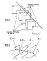
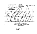
- an interpolated image can be formed from more than two input images, but as illustrated in FIG. 2, the methods using motion-compensated interpolation allow an intermediate image to be obtained. from two input images 11 and 12, using the motion field of the points of the image to be interpolated.
- the motion vector determines the corresponding points, A in 11 and B in 12 and therefore provides the addresses of the pixel considered as an object element, respectively in the mother images 11 and 12, the displacement being assumed to be linear between these two images.
- the motion vector D has two components Dx and Dy in the image plane (X, Y).
- faults can appear in motion-compensated interpolation, especially when motion as a model of change over time is no longer appropriate.
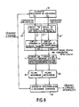
- FIG. 3 is a diagram illustrating the discovery (appearance) and the covering (disappearance) of object elements from a "mother" image 11 to a "mother” image 12, as well as the effect of a nonlinear motion.
- the small circles diagram the pixels, and an object present in the image has been diagrammed by crosses. This object is in non-linear movement since its position in the intermediate image is not the result of a translation having its origin and its end in corresponding pixels of the two mother images 11 and 12.
- the background in movement is found in the two mother images by a translation.
- the model given by the field of motion between 11 and 12 is not therefore not correct.
- the compensated temporal difference that is to say taking into account the movement, DFD is less than a threshold. Consequently for all the points P of the frame to be interpolated such that the temporal luminance differences inter-images compensated in motion are greater than a threshold s, the associated motion vector is declared defective and the corresponding point is marked in a matrix of consistency. Otherwise, the motion vector is declared right and the corresponding point of the matrix is not marked.
- This step of detecting faults in the motion estimation can be completed by a test on the difference in luminance between points with the same coordinates as the current point of the image to be interpolated in the mother images.
- This information is characteristic of the degree of resemblance between the points of the same coordinates in the mother images and makes it possible to know whether a simple linear interpolation, not taking account of the movement, is a suitable fall-back solution for these "defective points".
- the variance, or pseudo-variance is then compared to a threshold S3 , and the central point (or the block), is marked defective when V (or PV) is greater than S 3 .
- a first phase 1 of filtering the inconsistency information, called erosion is carried out: for each current point marked as defective, if the number of unmarked points in a block centered on this current point is greater than a fixed threshold S, then the point marked as defective in the previous step loses its marking in the binary matrix characterizing the defective vectors after erosion.
- the purpose of this step is to remove the small areas considered to be insignificant.
- the second phase II of the filtering is a so-called filling phase and comprises a first step 1 of so-called horizontal filling, a second step 2 of so-called vertical filling, and a third step 3 in which a so-called horizontal filling is carried out again.
- This filtering results in a new marking of the defective vectors.
- Figure 5 illustrates in more detail the erosion phase of the filtering of coherence information.
- the marking of defective points or blocks is symbolized by a blackening of the corresponding boxes of a matrix.
- the processing will apply to the adjacent blocks of the image, an element of the matrix corresponding to a block of pixels, thus reducing the number of treatments.
- the input binary matrix indicating the points or blocks marked as correct and the points or blocks marked as defective is tested by a conventional method of analysis, line by line.
- the first test consists in examining if the current element of the matrix (point or block) is marked. If it is not, it is transmitted as is at the output of the erosion device. If it is marked on the other hand, the number of elements marked in a 5x5 block of the matrix centered on the current element analyzed is calculated. This number of elements marked M is then to be compared with the threshold S.
- FIG. 6 illustrates the effect of the filling phase from an initial eroded matrix as it results from the previous phase, that is to say in which the isolated elements have been removed.
- a minimum predetermined segment length is chosen, for example 3 in this example: if the length of a segment of unmarked elements between two marked elements is less than 3, then the entire segment is marked.
- the first line filling phase has the effect in the example shown of adding two marked elements.
- the following column filling phase has the effect of marking all the unmarked elements belonging to vertical segments of length 1 or 2; only one vertical segment remains of length equal to 3.
- the following line filling phase also leads to the deletion of these marked points, the result being that the whole of the analyzed area represented in FIG. 6 is considered as defective as regards the analysis of the motion vector field.
- the fallback solution does not aim to faithfully interpolate the detected defective areas in the sense of movement analysis, but to produce luminance information which best masks the faults d 'interpolation.
- the defects of the motion compensation are due, as indicated above, on the one hand to the local spatial inhomogeneity of the movement which deforms the structures in the image, and on the other hand to the inhomogeneity temporal local genius which modifies these deformations over time, which creates significant visible defects.
- the essential objective of this fallback solution is therefore the homogenization of the field of movement in the moving areas. defective.
- the first interesting solution is a simple linear interpolation: this interpolation can be compared in fact to a motion-compensated interpolation with a motion vector of zero components in the XY plane, but instead of simply using two mother images as in the interpolation motion compensated, linear interpolation can be performed from a higher number of mother images, for example 4 or 6. In areas with defective motion, the luminance value resulting from motion compensated interpolation can then be replaced by the luminance value resulting from the linear interpolation.
- This linear interpolation is preferably calculated for all the points, in parallel with the motion-compensated interpolation so that a so-called "soft" switching can be carried out, instead of an abrupt switching, between the motion-compensated channel. and the linear path, such abrupt switching being capable of creating visible and annoying breaks. Consequently, the switching can be carried out as follows: from the binary matrix of coherence of the motion field, the unmarked pixels are set to zero. The marked pixels are meanwhile set to a non-zero value V.
- This two-value matrix of the motion field coherence information is then filtered by a low-pass filter and the resulting values a between O and V of the pixels of the new (non-binary) matrix make it possible to define a mixing coefficient i of the two interpolation paths.
- This masking is obtained by averaging filtering of the field of movement, by components.
- the average can be calculated for example in blocks of dimensions 7x7.
- the block diagram of the motion-compensated interpolation device with fallback solution according to the first method is represented in FIG. 7: the sequence of input images is applied simultaneously to a motion estimation device 10, to a motion compensated interpolation device 20 and a linear interpolation device 30.
- the motion compensated interpolation device processes the input sequence from information received from the motion estimation device 10.
- a output of the motion estimation device which supplies the motion vector field is connected to a coherence analysis circuit of the motion vector field 40 which includes a fault detection circuit 41 the output of which is connected to a filtering circuit 42 which performs the treatment described above, erosion then filling.
- a binary coherence matrix, in which the faulty motion vectors are marked is therefore available.
- This binary matrix is applied to a circuit 50 for defining the mixing coefficients i to be applied to a mixer 60 receiving the information from the motion compensated interpolation device 20 and that received from the linear interpolation device 30.
- the mixer 60 delivers the sequence of interpolated images in which the defects due to the imperfection of the model used for the motion-compensated interpolation are masked.
- Figure 8 is a block diagram of the motion compensated interpolation device with fallback solution according to the second method.
- the sequence of input images is applied as previously to a motion estimation device 10, the respectively vertical and horizontal components of the motion vectors being respectively applied to coherence analysis circuits 40 and 40 each comprising a fault detection circuit, respectively 41 'and 41 whose outputs provide binary matrices characteristic of points or blocks with "defective" motion vectors and are connected to filtering circuits, respectively 42 and 42 "which carry out the erosion and filling phases described above for each of the two binary matrices of defective vectors associated with the horizontal and vertical components respectively.
- the resulting binary matrices, after filtering, are transmitted to circuits 71 and 72 which zero the defective components.
- circuits have their outputs connected to the inputs of averaging filters, respectively 81 and 82, which supply the components of the motion vector directly processed to avoid abrupt transitions. These processed components are applied to the motion compensated interpolation device 20 which also receives the sequence of input images, and which supplies the sequence of interpolated images.
- the invention is not limited to the embodiments precisely described above, in particular with regard to the interpolation modes intended to replace the motion-compensated interpolation when the motion vector is detected to be defective.
Landscapes
- Engineering & Computer Science (AREA)
- Multimedia (AREA)
- Signal Processing (AREA)
- Television Systems (AREA)
- Compression Or Coding Systems Of Tv Signals (AREA)
- Apparatus For Radiation Diagnosis (AREA)
- Closed-Circuit Television Systems (AREA)
- Image Processing (AREA)
- Color Television Systems (AREA)
- Image Analysis (AREA)
Applications Claiming Priority (2)
| Application Number | Priority Date | Filing Date | Title |
|---|---|---|---|
| FR8904256 | 1989-03-31 | ||
| FR8904256A FR2645383B1 (fr) | 1989-03-31 | 1989-03-31 | Procede et dispositif d'interpolation temporelle d'images, a compensation de mouvement corrigee |
Publications (2)
| Publication Number | Publication Date |
|---|---|
| EP0390660A1 true EP0390660A1 (de) | 1990-10-03 |
| EP0390660B1 EP0390660B1 (de) | 1995-01-18 |
Family
ID=9380260
Family Applications (1)
| Application Number | Title | Priority Date | Filing Date |
|---|---|---|---|
| EP90400809A Expired - Lifetime EP0390660B1 (de) | 1989-03-31 | 1990-03-23 | Verfahren und Einrichtung zur temporalen Interpolation von Bildern mit korrigierter Bewegungskompensation |
Country Status (9)
| Country | Link |
|---|---|
| US (1) | US5057921A (de) |
| EP (1) | EP0390660B1 (de) |
| JP (1) | JP2831792B2 (de) |
| KR (1) | KR900015540A (de) |
| AT (1) | ATE117494T1 (de) |
| DE (1) | DE69016074T2 (de) |
| ES (1) | ES2066161T3 (de) |
| FR (1) | FR2645383B1 (de) |
| PT (1) | PT93628A (de) |
Cited By (8)
| Publication number | Priority date | Publication date | Assignee | Title |
|---|---|---|---|---|
| EP0508342A1 (de) * | 1991-04-12 | 1992-10-14 | Deutsche Thomson-Brandt Gmbh | Verfahren zur Codierung |
| US5309237A (en) * | 1992-03-31 | 1994-05-03 | Siemens Corporate Research, Inc. | Apparatus and method of compensating image-sequences for motion |
| EP0650293A3 (de) * | 1993-10-26 | 1995-06-14 | Seleco Spa | Verfahren zum Umwandlen der Bildfrequenz eines Videosignals von 50Hz zu 75Hz mit Bewegungskompensation und Einrichtung zur Durchführung dieses Verfahrens. |
| WO1997011557A1 (en) * | 1995-09-21 | 1997-03-27 | Innovision Limited | Motion compensated interpolation |
| EP0903946A1 (de) * | 1997-09-19 | 1999-03-24 | THOMSON multimedia | Gerät und Verfahren für Bildinterpolation mit Bewegungskompensierung |
| WO2001078389A1 (en) * | 2000-04-07 | 2001-10-18 | Snell & Wilcox Limited | Video signal processing |
| WO2007012659A1 (fr) * | 2005-07-28 | 2007-02-01 | Thomson Licensing | Dispositif de generation d'une image interpolee |
| FR3117248A1 (fr) | 2020-12-09 | 2022-06-10 | Safran Aircraft Engines | Procédé vidéo d’analyse d’une structure mécanique sous charge par amplification de petit déplacement |
Families Citing this family (32)
| Publication number | Priority date | Publication date | Assignee | Title |
|---|---|---|---|---|
| KR930009181B1 (ko) * | 1990-12-22 | 1993-09-23 | 삼성전자 주식회사 | 영상신호의 2차원 경사상관 보간방법 및 회로 |
| KR930011844B1 (ko) * | 1991-01-22 | 1993-12-21 | 삼성전자 주식회사 | 영상신호의 2차원 내삽에 의한 보간 및 주사선 변환회로 |
| EP0595895B1 (de) * | 1991-07-23 | 1997-12-29 | BRITISH TELECOMMUNICATIONS public limited company | Verfahren und vorrichtung zur bildinterpolation von bewegtbildern |
| US5400076A (en) * | 1991-11-30 | 1995-03-21 | Sony Corporation | Compressed motion picture signal expander with error concealment |
| GB2262853B (en) * | 1991-12-20 | 1995-07-19 | Sony Broadcast & Communication | Digital video signal processing |
| JP3093499B2 (ja) * | 1992-03-06 | 2000-10-03 | 三菱電機株式会社 | シーンチェンジ検出装置 |
| US5365280A (en) * | 1992-06-26 | 1994-11-15 | U.S. Philips Corporation | Method and apparatus for discriminating between movie film and non-movie film and generating a picture signal processing mode control signal |
| JP3177543B2 (ja) * | 1992-07-22 | 2001-06-18 | トウシバビデオプロダクツ プライベート リミテッド | 映像信号のノイズ低減装置 |
| US5642170A (en) * | 1993-10-11 | 1997-06-24 | Thomson Consumer Electronics, S.A. | Method and apparatus for motion compensated interpolation of intermediate fields or frames |
| US5592226A (en) * | 1994-01-26 | 1997-01-07 | Btg Usa Inc. | Method and apparatus for video data compression using temporally adaptive motion interpolation |
| WO1996033571A2 (en) * | 1995-04-11 | 1996-10-24 | Philips Electronics N.V. | Motion-compensated field rate conversion |
| AUPN727195A0 (en) * | 1995-12-21 | 1996-01-18 | Canon Kabushiki Kaisha | Motion detection method and apparatus |
| AU733460B2 (en) * | 1995-12-21 | 2001-05-17 | Canon Kabushiki Kaisha | Motion detection method and apparatus |
| US6804294B1 (en) * | 1998-08-11 | 2004-10-12 | Lucent Technologies Inc. | Method and apparatus for video frame selection for improved coding quality at low bit-rates |
| US6625333B1 (en) * | 1999-08-06 | 2003-09-23 | Her Majesty The Queen In Right Of Canada As Represented By The Minister Of Industry Through Communications Research Centre | Method for temporal interpolation of an image sequence using object-based image analysis |
| FR2820927B1 (fr) * | 2001-02-15 | 2003-04-11 | Thomson Multimedia Sa | Procede et dispositif de detection de fiabilite d'un champ de vecteurs mouvement |
| KR20050061556A (ko) * | 2002-10-22 | 2005-06-22 | 코닌클리케 필립스 일렉트로닉스 엔.브이. | 고장시 조치를 갖는 이미지 처리 유닛 |
| US7388603B2 (en) * | 2003-06-10 | 2008-06-17 | Raytheon Company | Method and imaging system with intelligent frame integration |
| FR2864878B1 (fr) * | 2004-01-06 | 2006-04-14 | Thomson Licensing Sa | Procede et systeme de determination du deplacement d'un pixel, et support d'enregistrement pour la mise en oeuvre du procede |
| JP4810088B2 (ja) * | 2004-12-17 | 2011-11-09 | キヤノン株式会社 | 画像処理装置、画像処理方法及びそのプログラム |
| JP4746514B2 (ja) * | 2006-10-27 | 2011-08-10 | シャープ株式会社 | 画像表示装置及び方法、画像処理装置及び方法 |
| WO2009073415A2 (en) * | 2007-11-30 | 2009-06-11 | Dolby Laboratories Licensing Corporation | Temporal image prediction |
| WO2009085205A1 (en) * | 2007-12-20 | 2009-07-09 | Integrated Device Technology, Inc. | Image interpolation with halo reduction |
| JP5453304B2 (ja) * | 2007-12-20 | 2014-03-26 | クゥアルコム・インコーポレイテッド | 適応探索範囲を用いた動き推定 |
| US8269885B2 (en) * | 2009-04-03 | 2012-09-18 | Samsung Electronics Co., Ltd. | Fade in/fade-out fallback in frame rate conversion and motion judder cancellation |
| US8537283B2 (en) | 2010-04-15 | 2013-09-17 | Qualcomm Incorporated | High definition frame rate conversion |
| JP2012230549A (ja) * | 2011-04-26 | 2012-11-22 | Sony Corp | 画像処理装置、画像処理方法、およびプログラム |
| DE102014112648A1 (de) * | 2014-08-29 | 2016-03-03 | Carl Zeiss Ag | Bildaufnahmevorrichtung und Verfahren zur Bildaufnahme |
| US9846929B2 (en) * | 2016-03-24 | 2017-12-19 | Hong Kong Applied Science and Technology Research Institute Company Limited | Fast density estimation method for defect inspection application |
| DE102017216065A1 (de) | 2017-09-12 | 2019-03-14 | Robert Bosch Gmbh | Verfahren und Vorrichtung zum Bewerten von Bildern, Betriebsassistenzverfahren und Betriebsvorrichtung |
| US12574521B1 (en) | 2022-09-20 | 2026-03-10 | Nvidia Corporation | Generating motion information of video frames |
| US12524850B1 (en) | 2022-09-20 | 2026-01-13 | Nvidia Corporation | Edge-enhanced video frame blending |
Citations (6)
| Publication number | Priority date | Publication date | Assignee | Title |
|---|---|---|---|---|
| US4383272A (en) * | 1981-04-13 | 1983-05-10 | Bell Telephone Laboratories, Incorporated | Video signal interpolation using motion estimation |
| EP0187641A1 (de) * | 1985-01-07 | 1986-07-16 | Nippon Hoso Kyokai | Fernsehsystemumsetzer |
| GB2172171A (en) * | 1985-03-04 | 1986-09-10 | Kokusai Denshin Denwa Co Ltd | Motion vector calculating system for detecting a moving object on a screen |
| US4668986A (en) * | 1984-04-27 | 1987-05-26 | Nec Corporation | Motion-adaptive interpolation method for motion video signal and device for implementing the same |
| EP0294282A1 (de) * | 1987-06-04 | 1988-12-07 | Thomson Grand Public | Verfahren zur temporalen Interpolation von Bildern und Einrichtung zur Durchführung dieses Verfahrens |
| EP0341769A1 (de) * | 1988-04-29 | 1989-11-15 | Laboratoires D'electronique Philips | Bildinterpolierungsgerät mit Bewegungsabschätzung und Kompensation und aus einem solchen Gerät bestehendes Konvertierungssystem für Fernsehstandards |
Family Cites Families (6)
| Publication number | Priority date | Publication date | Assignee | Title |
|---|---|---|---|---|
| US4692801A (en) * | 1985-05-20 | 1987-09-08 | Nippon Hoso Kyokai | Bandwidth compressed transmission system |
| SE448125B (sv) * | 1985-05-23 | 1987-01-19 | Context Vision Ab | Anordning for bestemning av graden av konstans hos en egenskap for ett omrade i en i diskreta bildelement uppdelad bild |
| US4679086A (en) * | 1986-02-24 | 1987-07-07 | The United States Of America As Represented By The Secretary Of The Air Force | Motion sensitive frame integration |
| DE3851786T2 (de) * | 1987-06-09 | 1995-03-09 | Sony Corp | Auswahl eines Bewegungsvektors in Fernsehbildern. |
| JP2634632B2 (ja) * | 1988-06-15 | 1997-07-30 | 株式会社日立製作所 | 動き検出回路 |
| GB2223141A (en) * | 1988-09-21 | 1990-03-28 | Sony Corp | Slow motion video signal generator with motion compensated interpolation |
-
1989
- 1989-03-31 FR FR8904256A patent/FR2645383B1/fr not_active Expired - Lifetime
-
1990
- 1990-03-21 US US07/496,930 patent/US5057921A/en not_active Expired - Lifetime
- 1990-03-23 DE DE69016074T patent/DE69016074T2/de not_active Expired - Lifetime
- 1990-03-23 EP EP90400809A patent/EP0390660B1/de not_active Expired - Lifetime
- 1990-03-23 ES ES90400809T patent/ES2066161T3/es not_active Expired - Lifetime
- 1990-03-23 AT AT90400809T patent/ATE117494T1/de active
- 1990-03-29 KR KR1019900004218A patent/KR900015540A/ko not_active Withdrawn
- 1990-03-30 PT PT93628A patent/PT93628A/pt not_active Application Discontinuation
- 1990-03-30 JP JP2084762A patent/JP2831792B2/ja not_active Expired - Lifetime
Patent Citations (6)
| Publication number | Priority date | Publication date | Assignee | Title |
|---|---|---|---|---|
| US4383272A (en) * | 1981-04-13 | 1983-05-10 | Bell Telephone Laboratories, Incorporated | Video signal interpolation using motion estimation |
| US4668986A (en) * | 1984-04-27 | 1987-05-26 | Nec Corporation | Motion-adaptive interpolation method for motion video signal and device for implementing the same |
| EP0187641A1 (de) * | 1985-01-07 | 1986-07-16 | Nippon Hoso Kyokai | Fernsehsystemumsetzer |
| GB2172171A (en) * | 1985-03-04 | 1986-09-10 | Kokusai Denshin Denwa Co Ltd | Motion vector calculating system for detecting a moving object on a screen |
| EP0294282A1 (de) * | 1987-06-04 | 1988-12-07 | Thomson Grand Public | Verfahren zur temporalen Interpolation von Bildern und Einrichtung zur Durchführung dieses Verfahrens |
| EP0341769A1 (de) * | 1988-04-29 | 1989-11-15 | Laboratoires D'electronique Philips | Bildinterpolierungsgerät mit Bewegungsabschätzung und Kompensation und aus einem solchen Gerät bestehendes Konvertierungssystem für Fernsehstandards |
Non-Patent Citations (4)
| Title |
|---|
| COMPUTER VISION, GRAPHICS AND IMAGE PROCESSING, vol. 21, no. 2, février 1983, pages 262-279, Academic Press, Inc., New York, US; M. YACHIDA: "Determining velocity maps by spatio-temporal neighborhoods from image sequences" * |
| ICC' 86 - IEEE INTERNATIONAL CONFERENCE ON COMMUNICATIONS, CONFERENCE RECORD, Toronto, 22-25 juin 1986, vol. 2, pages 1280-1284, IEEE, New York, US; Y. NINOMIYA et al.: "A motion vector detector for MUSE encoder" * |
| ICC'84, LINKS FOR THE FUTURE - IEEE PROCEEDINGS OF THE IEEE INTERNATIONAL CONFERENCE ON COMMUNICATIONS, Amsterdam, 14-17 mai 1984, vol. 2, pages 707-710, IEEE, New York, US; A. FURUKAWA et al.: "Motion-adaptive interpolation for videoconference pictures" * |
| SIGNAL PROCESSING, vol. 11, no. 4, décembre 1986, pages 387-404, Elsevier Science Publishers B.V., Amsterdam, NL; M. BIERLING et al.: "Motion compensating field interpolation using a hierarchically structured displacement estimator" * |
Cited By (15)
| Publication number | Priority date | Publication date | Assignee | Title |
|---|---|---|---|---|
| US5450133A (en) * | 1991-04-12 | 1995-09-12 | Deutsche Thomson-Brandt Gmbh | Motion compensated adaptive vertical filtering of an image representative signal |
| WO1992019071A1 (de) * | 1991-04-12 | 1992-10-29 | Deutsche Thomson-Brandt Gmbh | Verfahren zur codierung |
| TR25956A (tr) * | 1991-04-12 | 1993-11-01 | Thomson Brandt Gmbh | Hareketi telafi edilmis sakuli filtre etme icin bir usul. |
| EP0508342A1 (de) * | 1991-04-12 | 1992-10-14 | Deutsche Thomson-Brandt Gmbh | Verfahren zur Codierung |
| AU655460B2 (en) * | 1991-04-12 | 1994-12-22 | Deutsche Thomson-Brandt Gmbh | Coding process |
| US5309237A (en) * | 1992-03-31 | 1994-05-03 | Siemens Corporate Research, Inc. | Apparatus and method of compensating image-sequences for motion |
| EP0650293A3 (de) * | 1993-10-26 | 1995-06-14 | Seleco Spa | Verfahren zum Umwandlen der Bildfrequenz eines Videosignals von 50Hz zu 75Hz mit Bewegungskompensation und Einrichtung zur Durchführung dieses Verfahrens. |
| WO1997011557A1 (en) * | 1995-09-21 | 1997-03-27 | Innovision Limited | Motion compensated interpolation |
| EP0903946A1 (de) * | 1997-09-19 | 1999-03-24 | THOMSON multimedia | Gerät und Verfahren für Bildinterpolation mit Bewegungskompensierung |
| FR2768891A1 (fr) * | 1997-09-19 | 1999-03-26 | Thomson Multimedia Sa | Procede et dispositif d'interpolation temporelle d'images a compensation de mouvement |
| WO2001078389A1 (en) * | 2000-04-07 | 2001-10-18 | Snell & Wilcox Limited | Video signal processing |
| US7009656B2 (en) | 2000-04-07 | 2006-03-07 | Snell & Wilcox Limited | Video signal processing |
| WO2007012659A1 (fr) * | 2005-07-28 | 2007-02-01 | Thomson Licensing | Dispositif de generation d'une image interpolee |
| US8270491B2 (en) | 2005-07-28 | 2012-09-18 | Thomson Licensing | Device for generating an interpolated frame |
| FR3117248A1 (fr) | 2020-12-09 | 2022-06-10 | Safran Aircraft Engines | Procédé vidéo d’analyse d’une structure mécanique sous charge par amplification de petit déplacement |
Also Published As
| Publication number | Publication date |
|---|---|
| ATE117494T1 (de) | 1995-02-15 |
| ES2066161T3 (es) | 1995-03-01 |
| FR2645383A1 (fr) | 1990-10-05 |
| KR900015540A (ko) | 1990-10-27 |
| EP0390660B1 (de) | 1995-01-18 |
| FR2645383B1 (fr) | 1997-06-27 |
| DE69016074T2 (de) | 1995-05-24 |
| US5057921A (en) | 1991-10-15 |
| JP2831792B2 (ja) | 1998-12-02 |
| PT93628A (pt) | 1990-11-20 |
| JPH031787A (ja) | 1991-01-08 |
| DE69016074D1 (de) | 1995-03-02 |
Similar Documents
| Publication | Publication Date | Title |
|---|---|---|
| EP0390660B1 (de) | Verfahren und Einrichtung zur temporalen Interpolation von Bildern mit korrigierter Bewegungskompensation | |
| FR2766946A1 (fr) | Procede et dispositif de pretraitement pour estimation de mouvement | |
| EP0675652B1 (de) | Verfahren und Schaltung zur Bewegungsschätzung zwischen Bildern mit zwei Zeilensprunghalbbildern, und Vorrichtung zur digitalen Signalkodierung mit einer solchen Schaltung | |
| US7903848B2 (en) | Method for processing an image acquired through a guide consisting of a plurality of optical fibers | |
| EP0533888B1 (de) | Verfahren zur Pixel-Klassifizierung in einem Bild und zur temporalen Interpolation unter Verwendung dieser Klassifizierung. | |
| US20070153127A1 (en) | System and method for three dimensional comb filtering | |
| FR2648254A2 (fr) | Procede et dispositif d'estimation de mouvement dans une sequence d'images animees | |
| EP0781041A1 (de) | Verfahren zur Interpolation von Vollbilden | |
| FR2939265A1 (fr) | Procede de detection de mode film ou mode camera | |
| EP0418952B1 (de) | Vorrichtung zum Codieren von zweidimensionalen Informationen und entsprechende Decodiervorrichtung | |
| EP0347325B1 (de) | Verfahren und Installation zur Sendung von kompatiblen Hochauflösungsfernsehprogrammen | |
| FR2923024A1 (fr) | Procede de detection d'une cible | |
| FR2584553A1 (fr) | Appareil pour reduire le bruit d'un signal video composite et filtre recursif qui y est utilise | |
| FR2805429A1 (fr) | Procede de controle de la qualite numeriques distribuees par detection de faux contours | |
| EP0337565B1 (de) | Einrichtung zur Kodierung von Signalen, die eine Folge von Bildern darstellen und Übertragungssystem von Fernsehbildern mit hoher Auflösung mit einer solchen Einrichtung | |
| EP0780794A1 (de) | Verfahren zur Bewegungsschätzungskorrektur in aus periodischen Strukturen bestehenden Bilder | |
| FR2768891A1 (fr) | Procede et dispositif d'interpolation temporelle d'images a compensation de mouvement | |
| EP0410826A1 (de) | Iteratives Bewegungsabschätzungsverfahren zwischen einem Referenzbild und einem aktuellen Bild, und Verfahren zu ihrer Herstellung | |
| EP1223554A1 (de) | Verfahren zur Rauschverminderung | |
| EP0546141A1 (de) | Verfahren zur Umwandlung der Frequenz einer sich bewegenden Bildfolge | |
| WO1990000846A1 (fr) | Codage et decodage d'images de television a haute definition | |
| FR2699780A1 (fr) | Dispositif de traitement récursif de signal vidéo comprenant une pluralité de branches. | |
| FR2820927A1 (fr) | Procede et dispositif de detection de fiabilite d'un champ de vecteurs mouvement | |
| EP0780795A1 (de) | Bewegungsschätzungsverfahren | |
| EP1290879B1 (de) | Verfahren zur detektion von sättigung eines bewegungsvektorfeldes |
Legal Events
| Date | Code | Title | Description |
|---|---|---|---|
| PUAI | Public reference made under article 153(3) epc to a published international application that has entered the european phase |
Free format text: ORIGINAL CODE: 0009012 |
|
| AK | Designated contracting states |
Kind code of ref document: A1 Designated state(s): AT CH DE ES GB LI NL SE |
|
| 17P | Request for examination filed |
Effective date: 19910221 |
|
| 17Q | First examination report despatched |
Effective date: 19921208 |
|
| GRAA | (expected) grant |
Free format text: ORIGINAL CODE: 0009210 |
|
| AK | Designated contracting states |
Kind code of ref document: B1 Designated state(s): AT CH DE ES GB LI NL SE |
|
| PG25 | Lapsed in a contracting state [announced via postgrant information from national office to epo] |
Ref country code: NL Effective date: 19950118 Ref country code: AT Effective date: 19950118 |
|
| REF | Corresponds to: |
Ref document number: 117494 Country of ref document: AT Date of ref document: 19950215 Kind code of ref document: T |
|
| REG | Reference to a national code |
Ref country code: ES Ref legal event code: FG2A Ref document number: 2066161 Country of ref document: ES Kind code of ref document: T3 |
|
| REF | Corresponds to: |
Ref document number: 69016074 Country of ref document: DE Date of ref document: 19950302 |
|
| PGFP | Annual fee paid to national office [announced via postgrant information from national office to epo] |
Ref country code: AT Payment date: 19950328 Year of fee payment: 6 |
|
| PGFP | Annual fee paid to national office [announced via postgrant information from national office to epo] |
Ref country code: SE Payment date: 19950329 Year of fee payment: 6 |
|
| PGFP | Annual fee paid to national office [announced via postgrant information from national office to epo] |
Ref country code: NL Payment date: 19950331 Year of fee payment: 6 |
|
| PG25 | Lapsed in a contracting state [announced via postgrant information from national office to epo] |
Ref country code: SE Effective date: 19950418 |
|
| GBT | Gb: translation of ep patent filed (gb section 77(6)(a)/1977) |
Effective date: 19950327 |
|
| RAP2 | Party data changed (patent owner data changed or rights of a patent transferred) |
Owner name: THOMSON MULTIMEDIA |
|
| NLV1 | Nl: lapsed or annulled due to failure to fulfill the requirements of art. 29p and 29m of the patents act | ||
| REG | Reference to a national code |
Ref country code: CH Ref legal event code: PFA Free format text: THOMSON CONSUMER ELECTRONICS TRANSFER- THOMSON MULTIMEDIA S.A. |
|
| PLBE | No opposition filed within time limit |
Free format text: ORIGINAL CODE: 0009261 |
|
| STAA | Information on the status of an ep patent application or granted ep patent |
Free format text: STATUS: NO OPPOSITION FILED WITHIN TIME LIMIT |
|
| 26N | No opposition filed | ||
| REG | Reference to a national code |
Ref country code: GB Ref legal event code: IF02 |
|
| PGFP | Annual fee paid to national office [announced via postgrant information from national office to epo] |
Ref country code: CH Payment date: 20080313 Year of fee payment: 19 |
|
| PGFP | Annual fee paid to national office [announced via postgrant information from national office to epo] |
Ref country code: ES Payment date: 20080418 Year of fee payment: 19 |
|
| PGFP | Annual fee paid to national office [announced via postgrant information from national office to epo] |
Ref country code: GB Payment date: 20090226 Year of fee payment: 20 |
|
| PGFP | Annual fee paid to national office [announced via postgrant information from national office to epo] |
Ref country code: DE Payment date: 20090325 Year of fee payment: 20 |
|
| REG | Reference to a national code |
Ref country code: CH Ref legal event code: PL |
|
| PG25 | Lapsed in a contracting state [announced via postgrant information from national office to epo] |
Ref country code: CH Free format text: LAPSE BECAUSE OF NON-PAYMENT OF DUE FEES Effective date: 20090331 Ref country code: LI Free format text: LAPSE BECAUSE OF NON-PAYMENT OF DUE FEES Effective date: 20090331 |
|
| REG | Reference to a national code |
Ref country code: GB Ref legal event code: PE20 Expiry date: 20100322 |
|
| REG | Reference to a national code |
Ref country code: ES Ref legal event code: FD2A Effective date: 20090324 |
|
| PG25 | Lapsed in a contracting state [announced via postgrant information from national office to epo] |
Ref country code: GB Free format text: LAPSE BECAUSE OF EXPIRATION OF PROTECTION Effective date: 20100322 |
|
| PG25 | Lapsed in a contracting state [announced via postgrant information from national office to epo] |
Ref country code: ES Free format text: LAPSE BECAUSE OF NON-PAYMENT OF DUE FEES Effective date: 20090324 |
|
| PG25 | Lapsed in a contracting state [announced via postgrant information from national office to epo] |
Ref country code: DE Free format text: LAPSE BECAUSE OF EXPIRATION OF PROTECTION Effective date: 20100323 |