EP0391027A2 - Compass, particularly for draughtsmen - Google Patents
Compass, particularly for draughtsmen Download PDFInfo
- Publication number
- EP0391027A2 EP0391027A2 EP90101379A EP90101379A EP0391027A2 EP 0391027 A2 EP0391027 A2 EP 0391027A2 EP 90101379 A EP90101379 A EP 90101379A EP 90101379 A EP90101379 A EP 90101379A EP 0391027 A2 EP0391027 A2 EP 0391027A2
- Authority
- EP
- European Patent Office
- Prior art keywords
- compass
- rod
- runner
- slider
- bow
- Prior art date
- Legal status (The legal status is an assumption and is not a legal conclusion. Google has not performed a legal analysis and makes no representation as to the accuracy of the status listed.)
- Granted
Links
Images

Classifications
-
- B—PERFORMING OPERATIONS; TRANSPORTING
- B43—WRITING OR DRAWING IMPLEMENTS; BUREAU ACCESSORIES
- B43L—ARTICLES FOR WRITING OR DRAWING UPON; WRITING OR DRAWING AIDS; ACCESSORIES FOR WRITING OR DRAWING
- B43L9/00—Circular curve-drawing or like instruments
- B43L9/16—Features common to compasses, dividers, and callipers
- B43L9/22—Leg-angle adjusting-means separate from pivots
Definitions
- the present invention relates to a compass, particularly to a draughtsman compass of the type usually called bow compass or spring bow compass.
- the bow compass is a compass adapted to draw circles or sections of circles of small radius and it is generally provided in two basic types.
- a first type of bow compass has two hinged rods holding a point at each of their lower ends; one of the points can be substituted by a lead holder or a drawing pen.
- a threaded bar has one end fastened to a median portion of one of the rods and engages a ring associated to the other rod but adapted to be rotated to finely adjust the distance between the two rods.
- a rod element has a longitudinal bore in which a point is slidable along its longitudinal axis; a resilient member is associated to the rod element and its distance from the rod element itself, i.e. the aperture of the compass, is adjusted by means of a screw.
- a lead holder or a drawing pen can be fastened to the resilient member.
- the bow compasses of the prior art are susceptible to improvements regarding their mechanical reliability and their operation, especially if their structure is provided in plastics, for example, instead of the usual metallic materials.
- the traditional bow compasses are also rather heavy in order to ensure a sturdy structure for a precise operation.
- the aim of the present invention is that of providing a compass for draughtsmen, particularly a bow compass, that, owing to a particular geometrical configuration, eases the hand movement in the drawing and at the same time ensures an absolute precision.
- an object of the invention is that of providing a bow compass which is constructively simple and easy to use.
- Another object of the invention is that of providing a bow compass having low manufacturing costs.
- a compass particularly for draughtsmen, comprising a first and a second rod elements, said second rod element being hinged to said first rod element at their upper ends, a point being associated with the lower end of said first element, fastening means for drawing means being associated with the lower end of said second element, characterized in that it comprises a slider member having a first end slidable in a first runner in said first rod element and a second end slidable in a second runner in said second element, said first and second runners being laid out in said first and second rod elements such that a progressive shift of said slider corresponds to a progressive aperture of said first and second rod elements relatively to each other.
- a draughtsman compass 1 will be described, of the type usually called bow compass, adapted to draw circles of small radius.
- the bow compass 1 comprises a first rod element 2 hinged to a second rod element 3 by means of an upper head 4.
- the lower end of the first element 2 has a point 5, while the lower end of the second element 3 has a fastening means 6 for drawing means such as, for example, a lead holder or a drawing pen, not illustrated in the drawings for brevity.
- a first runner is provided by means of two rectilinear grooves 7, on opposite sides of the first element, parallely laid out on the axis of the same first element.
- a second runner is formed on the second element 3 and is provided by means of two grooves 8, again on opposite sides of the second element, slanted of a set angle relatively to the axis of the second element.
- the runners of the first and second rod elements are engaged by the ends of a slider element 9 comprising a core 10 and two plates 11 provided with pins 12 adapted to slide in the grooves 7 and 8.
- a threaded bore 13 is provided in the core 10 and is engaged by a screw element 14 supported on the first rod element 2.
- the screw element 14 is substantially at the axis of the first element 2 and is inserted upwardly in the hand grip 15 of the bow compass.
- a knob 16 is fastened on the upper end of the screw element to manually rotate the screw element itself.
- the operation of the bow compass is very simple, it is in fact sufficient to rotate the knob 16 for axially displacing the slider 9 causing the two rod elements 2 ,3 to open or close, adjusting the aperture of the compass, because of the relative configuration of the grooves 7 and 8.
- an advantage of the invention is that of the hand grip which is provided on the axis of rotation of the bow compass itself and which comprises also the aperture adjusting knob.
- Another advantage of the particular structure of the bow compass according to the invention is that of allowing the use of different materials still keeping a remarkable mechanical reliability.
- the compass according to the invention may have numerous modifications and variations, all within the inventive concept; furthermore, all the details may be substituted with technically equivalent elements.
- the materials employed, as well as the dimensions, may be any according to the specific needs and the state of the art.
Landscapes
- Purses, Travelling Bags, Baskets, Or Suitcases (AREA)
- Mechanical Control Devices (AREA)
- Transmission Devices (AREA)
- Length-Measuring Instruments Using Mechanical Means (AREA)
Abstract
Description
- The present invention relates to a compass, particularly to a draughtsman compass of the type usually called bow compass or spring bow compass.
- The bow compass is a compass adapted to draw circles or sections of circles of small radius and it is generally provided in two basic types.
- A first type of bow compass has two hinged rods holding a point at each of their lower ends; one of the points can be substituted by a lead holder or a drawing pen.
- A threaded bar has one end fastened to a median portion of one of the rods and engages a ring associated to the other rod but adapted to be rotated to finely adjust the distance between the two rods.
- In the other type of bow compass, a rod element has a longitudinal bore in which a point is slidable along its longitudinal axis; a resilient member is associated to the rod element and its distance from the rod element itself, i.e. the aperture of the compass, is adjusted by means of a screw. A lead holder or a drawing pen can be fastened to the resilient member.
- The bow compasses of the prior art are susceptible to improvements regarding their mechanical reliability and their operation, especially if their structure is provided in plastics, for example, instead of the usual metallic materials.
- The traditional bow compasses are also rather heavy in order to ensure a sturdy structure for a precise operation.
- The aim of the present invention is that of providing a compass for draughtsmen, particularly a bow compass, that, owing to a particular geometrical configuration, eases the hand movement in the drawing and at the same time ensures an absolute precision.
- Within this aim, an object of the invention, is that of providing a bow compass which is constructively simple and easy to use.
- Another object of the invention is that of providing a bow compass having low manufacturing costs.
- Not a least object, is that of providing a compass with a new and likeable styling. The above aim, as well as these and other objects that will be more apparent later, are achieved by a compass, particularly for draughtsmen, comprising a first and a second rod elements, said second rod element being hinged to said first rod element at their upper ends, a point being associated with the lower end of said first element, fastening means for drawing means being associated with the lower end of said second element, characterized in that it comprises a slider member having a first end slidable in a first runner in said first rod element and a second end slidable in a second runner in said second element, said first and second runners being laid out in said first and second rod elements such that a progressive shift of said slider corresponds to a progressive aperture of said first and second rod elements relatively to each other.
- Further characteristics and advantages of the invention will be more apparent by the following description of a preferred embodiment of the invention, illustrated,by way of example in the enclosed drawings in which:
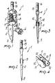
- Fig. 1 is an isometric view of a bow compass according to the invention;
- Fig. 2 is a side elevated view of the bow compass;
- Fig. 3 is a sectioned side view of the bow compass;
- Fig. 4 is an isometric view of the slider element;
- Figs. 5 and 6 are side elevated views of the bow compass, respectively in the closed position and in a partially open position;
- Fig. 7 is partially sectioned side elevated view of the bow compass.
- With reference to the above figures, a
draughtsman compass 1 will be described, of the type usually called bow compass, adapted to draw circles of small radius. - The
bow compass 1 comprises afirst rod element 2 hinged to asecond rod element 3 by means of anupper head 4. - The lower end of the
first element 2 has apoint 5, while the lower end of thesecond element 3 has a fastening means 6 for drawing means such as, for example, a lead holder or a drawing pen, not illustrated in the drawings for brevity. - On the
first rod element 2, a first runner is provided by means of tworectilinear grooves 7, on opposite sides of the first element, parallely laid out on the axis of the same first element. - A second runner is formed on the
second element 3 and is provided by means of twogrooves 8, again on opposite sides of the second element, slanted of a set angle relatively to the axis of the second element. - The runners of the first and second rod elements are engaged by the ends of a
slider element 9 comprising acore 10 and twoplates 11 provided withpins 12 adapted to slide in thegrooves - A threaded
bore 13 is provided in thecore 10 and is engaged by ascrew element 14 supported on thefirst rod element 2. - As better shown in Fig. 7, the
screw element 14 is substantially at the axis of thefirst element 2 and is inserted upwardly in thehand grip 15 of the bow compass. - A
knob 16 is fastened on the upper end of the screw element to manually rotate the screw element itself. - The operation of the bow compass is very simple, it is in fact sufficient to rotate the
knob 16 for axially displacing theslider 9 causing the tworod elements grooves - It has been practically observed how the invention achieves the intended aim and objects by providing a bow compass of great mechanical precision and at the same time of easy use; an advantage of the invention is that of the hand grip which is provided on the axis of rotation of the bow compass itself and which comprises also the aperture adjusting knob.
- Another advantage of the particular structure of the bow compass according to the invention is that of allowing the use of different materials still keeping a remarkable mechanical reliability.
- The compass according to the invention may have numerous modifications and variations, all within the inventive concept; furthermore, all the details may be substituted with technically equivalent elements.
- The materials employed, as well as the dimensions, may be any according to the specific needs and the state of the art.
- Where technical features mentioned in any claim are followed by reference signs, those reference signs have been included for the sole purpose of increasing the intelligibility of the claims and accordingly, such reference signs do not have any limiting effect on the scope of each element identified by way of example by such reference signs.
Claims (5)
Applications Claiming Priority (2)
| Application Number | Priority Date | Filing Date | Title |
|---|---|---|---|
| IT1981589 | 1989-03-20 | ||
| IT8919815A IT1228671B (en) | 1989-03-20 | 1989-03-20 | COMPASSO, PARTICULARLY FOR DESIGNERS. |
Publications (3)
| Publication Number | Publication Date |
|---|---|
| EP0391027A2 true EP0391027A2 (en) | 1990-10-10 |
| EP0391027A3 EP0391027A3 (en) | 1990-11-22 |
| EP0391027B1 EP0391027B1 (en) | 1994-04-13 |
Family
ID=11161512
Family Applications (1)
| Application Number | Title | Priority Date | Filing Date |
|---|---|---|---|
| EP90101379A Expired - Lifetime EP0391027B1 (en) | 1989-03-20 | 1990-01-24 | Compass, particularly for draughtsmen |
Country Status (4)
| Country | Link |
|---|---|
| EP (1) | EP0391027B1 (en) |
| DE (1) | DE69008013T2 (en) |
| ES (1) | ES2050850T3 (en) |
| IT (1) | IT1228671B (en) |
Cited By (1)
| Publication number | Priority date | Publication date | Assignee | Title |
|---|---|---|---|---|
| WO1997031787A1 (en) * | 1996-03-02 | 1997-09-04 | Bernhard Hauri | Pair of compasses with holder part |
Family Cites Families (6)
| Publication number | Priority date | Publication date | Assignee | Title |
|---|---|---|---|---|
| DE77106C (en) * | H. SCHWARTZ in Berlin, Arndtstr. 44 | Compass with measuring scale attached to the head | ||
| BE347916A (en) * | 1928-01-23 | |||
| US1958989A (en) * | 1932-07-19 | 1934-05-15 | Fischer John | Compass |
| GB448202A (en) * | 1936-01-08 | 1936-06-04 | Universal Woodworking Company | Improvements in drawing compasses and dividers |
| US2864172A (en) * | 1956-11-14 | 1958-12-16 | Buck Ralph | Divider |
| CS213617B1 (en) * | 1977-12-06 | 1982-04-09 | Zdenko Stanicek | Catching head particularly for industrial robots |
-
1989
- 1989-03-20 IT IT8919815A patent/IT1228671B/en active
-
1990
- 1990-01-24 ES ES90101379T patent/ES2050850T3/en not_active Expired - Lifetime
- 1990-01-24 DE DE69008013T patent/DE69008013T2/en not_active Expired - Fee Related
- 1990-01-24 EP EP90101379A patent/EP0391027B1/en not_active Expired - Lifetime
Cited By (1)
| Publication number | Priority date | Publication date | Assignee | Title |
|---|---|---|---|---|
| WO1997031787A1 (en) * | 1996-03-02 | 1997-09-04 | Bernhard Hauri | Pair of compasses with holder part |
Also Published As
| Publication number | Publication date |
|---|---|
| IT1228671B (en) | 1991-07-03 |
| IT8919815A0 (en) | 1989-03-20 |
| EP0391027B1 (en) | 1994-04-13 |
| EP0391027A3 (en) | 1990-11-22 |
| ES2050850T3 (en) | 1994-06-01 |
| DE69008013D1 (en) | 1994-05-19 |
| DE69008013T2 (en) | 1994-11-17 |
Similar Documents
| Publication | Publication Date | Title |
|---|---|---|
| US3030060A (en) | Curtain rod mounting devices | |
| DE1213194B (en) | Locking device for a slide | |
| CN110389522B (en) | Lever device for fixing a bracelet to a wristwatch and wristwatch | |
| EP0391027A2 (en) | Compass, particularly for draughtsmen | |
| US5235754A (en) | Beam compass | |
| US4278066A (en) | Flipper rest | |
| US4000950A (en) | Writing instrument | |
| US878626A (en) | Fish stringer or holder. | |
| US3825976A (en) | Writing instrument | |
| DE3400850C2 (en) | Multi-purpose knife | |
| US3237308A (en) | Draftsman's compass | |
| US4263753A (en) | Interchangeable faceting apparatus with reversible dual indexing mechanism | |
| DE4208372C2 (en) | Monostable electrical switching device | |
| DE972501C (en) | Permanent magnetic focusing device for the cathode ray tube of a television receiver | |
| US3001510A (en) | Improvements in lead dropping pencils | |
| DE812052C (en) | Device for writing by means of an electric arc on metals | |
| US2298730A (en) | Indicating slide device | |
| DE660124C (en) | To a writing device, e.g. B. a fountain pen, pencil o. The like., Clampable electrical lighting device | |
| US5956856A (en) | Drawing board assembly | |
| DE1943447A1 (en) | Thrust compass | |
| SU1761553A1 (en) | Collet pencil | |
| DE2802766A1 (en) | Screw holder attachments for screwdriver blade - has leaf springs secured to blade by sliding tube and fixed ring | |
| KR200141353Y1 (en) | Digital compasses | |
| US2873617A (en) | Vise handles | |
| US2809795A (en) | Holding device |
Legal Events
| Date | Code | Title | Description |
|---|---|---|---|
| PUAI | Public reference made under article 153(3) epc to a published international application that has entered the european phase |
Free format text: ORIGINAL CODE: 0009012 |
|
| PUAL | Search report despatched |
Free format text: ORIGINAL CODE: 0009013 |
|
| AK | Designated contracting states |
Kind code of ref document: A2 Designated state(s): CH DE ES FR GB LI NL |
|
| AK | Designated contracting states |
Kind code of ref document: A3 Designated state(s): CH DE ES FR GB LI NL |
|
| 17P | Request for examination filed |
Effective date: 19901215 |
|
| 17Q | First examination report despatched |
Effective date: 19920901 |
|
| GRAA | (expected) grant |
Free format text: ORIGINAL CODE: 0009210 |
|
| AK | Designated contracting states |
Kind code of ref document: B1 Designated state(s): CH DE ES FR GB LI NL |
|
| PG25 | Lapsed in a contracting state [announced via postgrant information from national office to epo] |
Ref country code: NL Effective date: 19940413 Ref country code: LI Effective date: 19940413 Ref country code: CH Effective date: 19940413 |
|
| REF | Corresponds to: |
Ref document number: 69008013 Country of ref document: DE Date of ref document: 19940519 |
|
| REG | Reference to a national code |
Ref country code: ES Ref legal event code: FG2A Ref document number: 2050850 Country of ref document: ES Kind code of ref document: T3 |
|
| REG | Reference to a national code |
Ref country code: CH Ref legal event code: PL |
|
| ET | Fr: translation filed | ||
| NLV1 | Nl: lapsed or annulled due to failure to fulfill the requirements of art. 29p and 29m of the patents act | ||
| PG25 | Lapsed in a contracting state [announced via postgrant information from national office to epo] |
Ref country code: GB Effective date: 19950124 |
|
| PLBE | No opposition filed within time limit |
Free format text: ORIGINAL CODE: 0009261 |
|
| STAA | Information on the status of an ep patent application or granted ep patent |
Free format text: STATUS: NO OPPOSITION FILED WITHIN TIME LIMIT |
|
| 26N | No opposition filed | ||
| GBPC | Gb: european patent ceased through non-payment of renewal fee |
Effective date: 19950124 |
|
| PGFP | Annual fee paid to national office [announced via postgrant information from national office to epo] |
Ref country code: FR Payment date: 19960131 Year of fee payment: 7 Ref country code: ES Payment date: 19960131 Year of fee payment: 7 |
|
| PGFP | Annual fee paid to national office [announced via postgrant information from national office to epo] |
Ref country code: DE Payment date: 19960327 Year of fee payment: 7 |
|
| PG25 | Lapsed in a contracting state [announced via postgrant information from national office to epo] |
Ref country code: ES Free format text: LAPSE BECAUSE OF NON-PAYMENT OF DUE FEES Effective date: 19970125 |
|
| PG25 | Lapsed in a contracting state [announced via postgrant information from national office to epo] |
Ref country code: FR Effective date: 19970930 |
|
| PG25 | Lapsed in a contracting state [announced via postgrant information from national office to epo] |
Ref country code: DE Effective date: 19971001 |
|
| REG | Reference to a national code |
Ref country code: FR Ref legal event code: ST |
|
| REG | Reference to a national code |
Ref country code: ES Ref legal event code: FD2A Effective date: 19990301 |