EP0391982B1 - Enrouleurs de ceintures de securite dans des vehicules - Google Patents
Enrouleurs de ceintures de securite dans des vehicules Download PDFInfo
- Publication number
- EP0391982B1 EP0391982B1 EP89903125A EP89903125A EP0391982B1 EP 0391982 B1 EP0391982 B1 EP 0391982B1 EP 89903125 A EP89903125 A EP 89903125A EP 89903125 A EP89903125 A EP 89903125A EP 0391982 B1 EP0391982 B1 EP 0391982B1
- Authority
- EP
- European Patent Office
- Prior art keywords
- shaft
- reel
- slewing
- type retractor
- sides
- Prior art date
- Legal status (The legal status is an assumption and is not a legal conclusion. Google has not performed a legal analysis and makes no representation as to the accuracy of the status listed.)
- Expired - Lifetime
Links
- 230000000903 blocking effect Effects 0.000 claims abstract description 18
- 230000007246 mechanism Effects 0.000 claims abstract description 5
- 238000004804 winding Methods 0.000 claims description 13
- 238000010276 construction Methods 0.000 claims description 4
- 230000004913 activation Effects 0.000 claims description 2
- 230000008878 coupling Effects 0.000 claims description 2
- 238000010168 coupling process Methods 0.000 claims description 2
- 238000005859 coupling reaction Methods 0.000 claims description 2
- 230000009977 dual effect Effects 0.000 claims 2
- 238000006073 displacement reaction Methods 0.000 claims 1
- 230000007935 neutral effect Effects 0.000 claims 1
- 230000001360 synchronised effect Effects 0.000 abstract description 7
- 230000001133 acceleration Effects 0.000 abstract description 2
- 230000002146 bilateral effect Effects 0.000 abstract 1
- 230000005540 biological transmission Effects 0.000 description 4
- 238000000034 method Methods 0.000 description 3
- 230000008569 process Effects 0.000 description 3
- 230000008901 benefit Effects 0.000 description 2
- 239000000463 material Substances 0.000 description 2
- 208000012886 Vertigo Diseases 0.000 description 1
- 230000000694 effects Effects 0.000 description 1
- 230000006872 improvement Effects 0.000 description 1
- 230000002452 interceptive effect Effects 0.000 description 1
- 239000002184 metal Substances 0.000 description 1
- 230000035939 shock Effects 0.000 description 1
- 230000007480 spreading Effects 0.000 description 1
Images
Classifications
-
- B—PERFORMING OPERATIONS; TRANSPORTING
- B60—VEHICLES IN GENERAL
- B60R—VEHICLES, VEHICLE FITTINGS, OR VEHICLE PARTS, NOT OTHERWISE PROVIDED FOR
- B60R22/00—Safety belts or body harnesses in vehicles
- B60R22/34—Belt retractors, e.g. reels
- B60R22/36—Belt retractors, e.g. reels self-locking in an emergency
Definitions
- the invention relates to a lifting roller retractor for vehicle seat belts according to the preamble of claim 1.
- reels are known under the term "lifting roller retractor" and belong to the prior art.
- the basic idea was first described in US-A-3,074,761.
- the proposed solution in DE-A-34 18 378 is the basis for the first, standard lifting roller retractor which, for the first time, synchronously transfers the shaft with its toothing into the toothing of the housing both in a vehicle-sensitive and in a belt-sensitive manner.
- DE-A-33 07 093 also relates to a lifting roller retractor.
- a system-related disadvantage is that you are not very variable in the belt extension direction.
- the belt extension direction is determined by the position of the teeth in the housing and must be observed within narrow limits (approx. +/- 15 ° from the target direction). Even an uncontrolled slanting of the webbing can lead to problems if it exceeds an allowable dimension, since the shaft can be synchronized on both sides got to.
- the object of the invention is to ensure an absolutely safe control of the shaft even under difficult conditions (belt slant pull-out) on both sides with the smallest possible outer dimensions of the retractor, the shaft bearings should remain load-free and the permitted belt pull-out direction (from the belt reel) at least a range of 90 ° should cover, and to achieve a high resilience.
- the solution according to the invention is a "heavy-duty solution" to which the term “foolproof” can be applied with regard to load security and load capacity.
- the synchronized pre-blocking of the shaft on both sides causes a force-controlled entry of the shaft into the blocking toothing under all conceivable, difficult circumstances. Not only on the mechanical side, but also on the spring side, the shaft no longer has a degree of freedom to follow a different control path than the one specified in the design.
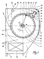
- the large permissible belt webbing extension range of approximately 120 ° is clearly shown in FIG. 1. Due to the additional support force of the double bolt 2, the shaft 1 is held firmly in the locking toothing 4 in all indicated directions of traction from F a to F z , thereby ensuring a secure load transmission.
- the shaft journal 23 remains completely load-free during the load transmission, so that it can be thin and possibly made of plastic to achieve low frictional resistance.
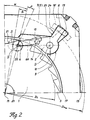
- the double bolt 2 is rotatably arranged in the plane of the housing leg 7 on the mechanical and spring side and is rigidly and non-rotatably formed as a one-piece part via a bracket.
- a control pin 14 of the double bolt 2 on the mechanical side extends through an opening in the leg plate 12 and engages from behind in a guide groove 15 of a control disk 16.
- This control disk 16 deflects the double bolt 2 in the case of a webbing-sensitive and / or vehicle-sensitive activation and when the belt is pulled out into the locked position. This movement process of the control of the double bolt 2 in a tooth space of the shaft toothing 3 is synchronized.
- Load-bearing blocking teeth made of metal can never be designed in such a way that a free, not positively controlled pivoting-in process of a bolt takes place with 100% certainty.
- a tooth-on-tooth blocking is possible, which strikes back the bar that is swinging in.
- the term "lever bouncing" has become established in specialist circles for this phenomenon. Controls from / into load-absorbing blockages must be synchronized.
- the synchronized control of the double bolt 2 into the shaft toothing 3 is accomplished via the control pin 14.
- the double bar 2 is already controlled up to the tooth base diameter Di.
- the shaft 1 Due to the additional support component that the articulated double bolt 2 produces, the shaft 1 always has a turning moment in the locking toothing 4 in all belt extension directions from F a to F z . This fact also makes the load transmission absolutely safe under all possible interference (e.g. additional impacts against the direction of control). This ensures high resilience.
- the tooth tip 6 of the double bolt 2 is provided with an angle ⁇ , the swivel angle of the shaft 1, so that there is a full-surface contact with the shaft teeth 3 in the fully blocked state.
- the bracket 8 of the double locking bar 2 is widened towards the front and rear with support surfaces 19, 19 'which constantly move behind the housing legs 7. In the deflected state of the double bolt 2, this results in a form-fitting support possibility for the shaft 1 in the axial direction.
- the flange 17 of the shaft 1 can be made so large that there is a constant overlap with the tooth region 6b of the double bolt 2 even in the idle state. Then axial impacts on the shaft 1 are safely intercepted by means of an inelastic, metallic positive lock even before deflection with belt pull-out.
- the central rotation and position fixation of the double bolt 2 takes place via a pin 11 of the leg plate 12, which engages in the bore 10 of the double bolt 2.
- the double bar 2 is supported by force against an arcuate recess 9 in the plane of the housing leg 7.
- the rotational movement of the double bar is intercepted by the stop of one web 24 against the leg wall 25.
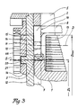
- Fig. 3 illustrates the construction in section.
- the pivot point S of the control disc 16 lies on the same radius as the pivot point axis S 'for the shaft 1.
- a pin 20 at the relevant point on the leg plate 12, which engages in a bore 21 of the control disc 16, ensures the positional fixation.
- the bore 21 is designed as a short elongated hole with radii around the shaft center M, since the control disk 16 completes two sequences of movements in succession. First, it rotates around the center of the shaft M by a small angle ⁇ (max. 5 °) in order to guide the double bolt 2 into the shaft toothing 3. In this state, the shaft 1 and the control disk 16 are connected to one another in a form-fitting manner via a controlled sensor bar (not shown).
- control disk 16 strikes with its elongated hole 21 against the pin 20. This relationship can be seen in broken lines from FIG. 2.
- the shaft 1 pivots with the control disk 16 (both coupled) about the pivot point axis S 'into the final blocking position.
- the sequence of movements of the control disk 16 is therefore: 1. turning, 2. swiveling.
- the control movement of the winding shaft is of particular importance in the case of a lifting roller retractor since, in the event of danger, it must be transferred synchronously from the spring-loaded rest position to the blocking position in fractions of a second.
- the load capacity is further supported by the double bolt 2 securing the shaft securely during the load and possibly also transferring a small part of the load depending on the belt extension direction.
Landscapes
- Engineering & Computer Science (AREA)
- Mechanical Engineering (AREA)
- Automotive Seat Belt Assembly (AREA)
Abstract
Claims (11)
- Enrouleur de ceinture de sécurité dans des véhicules avec un axe d'enroulement rotatif (1) pour enrouler la ceinture (13) dont le mouvement de déroulement doit être bloqué en cas de danger par un dispositif de blocage sensible au véhicule et/ou sensible à la ceinture, le blocage étant effectué par l'intermédiaire d'une denture sur l'arbre (1) qui est logé dans le boitier de manière à pouvoir pivoter radialement, de sorte que l'arbre (1) est pivoté contre la force d'un ressort en position de blocage, les dentures d'arbre (3) bilatérales entrant des deux côtés en prise avec les dentures (4) solidaires du boîtier, et les dentures (3) côté arbre s'étendant des deux côtés à l'intérieur des plans des deux branches de boîtier, le mouvement d'activation de l'arbre (1) pour son engagement dans la denture (4) solidaire du boîtier après l'embrayage avec un disque de commande (16) par l'intermédiaire de pièces captrices est formé à partir d'un premier mouvement de pivotement à un angle (β) autour d'un point (M) qui constitue le point central de l'arbre d'enroulement (1) alors qu'un verrou s'engage dans la denture (3) de l'arbre, et un deuxième mouvement de pivotement à un angle (γ) autour d'un point (S') qui se trouve sur le diamètre de la racine de la dent (Di) de la dent de la denture de l'arbre dans laquelle le verrou s'engage alors que l'arbre (1) s'appuie des deux côtés contre les pointes de la dent (6) du verrou,
caractérisé
en ce que le verrou est formé comme double verrou (2) qui s'engage des deux côtés dans la denture de l'arbre (3) et que l'appui du double verrou (2) dans la position de blocage se fait contre une échancrure circulaire (9) dans chacune des branches de boîtier (7). - Enrouleur de ceinture selon la revendication 1, caractérisé en ce que le double verrou (2) est logé par une zone dentée (6, 6b) et une zone tournante (D) des deux côtés dans le plan des branches de boîtier (7) et à l'intérieur du diamètre maximal de la ceinture (D max) et qu'un étrier (8) en dehors du diamètre d'enroulement de la ceinture (D max) relie les deux côtés.
- Enrouleur de ceinture selon la revendication 1, caractérisé en ce que la denture de blocage (4) dans le boîtier (5) est formée géométriquement des deux côtés de manière à ce qu'elle corresponde au contour extérieur de la denture de l'arbre (3) qui est pivotée autour du point (S') à l'angle (γ)
- Enrouleur de ceinture selon la revendication 1, caractérisé en ce que le disque de commande (16) présente un perçage (21) comme trou oblong avec un rayon autour du point central de l'arbre (M) et que le mouvement de commande du disque de commande (16) est effectué d'abord en tant que pivotement autour du point central de l'arbre (M), le double verrou (2) étant dévié vers l'extérieur par le tenon de commande (14) de sorte qu'un pivotement du disque de commande (16) raccordé à l'arbre (1) autour de l'axe de pivotement (S') dans la position de blocage définitive est effectué.
- Enrouleur de ceinture selon les revendications 1 et 4, caractérisé en ce que le point de pivotement du disque de commande (16) se trouve sur l'axe du point de pivotement (S) défini par le diamètre de la racine de la dent (Di) de l'axe (1) et l'angle (α) et qui est formé par une construction de perçage-tenon (20/21) entre la plaque de branche (12) et le disque de commande (16).
- Enrouleur de ceinture selon l'une quelconque des revendications 1 à 5, caractérisé en ce que le double verrou (2) présente sur le côté mécanique un tenon de commande (14) qui s'étend à travers la plaque de branche (12) dans une rainure de guidage (15) à l'arrière du disque de commande (16) et est déplacé par ce dernier dans la position de repos et la position de blocage.
- Enrouleur de ceinture selon l'une quelconque des revendications 1 à 6, caractérisé en ce que le double verrou (2) présente des éléments d'appui (19, 19') pour s'appuyer contre les branches (7), à l'aide desquels un déplacement axial de l'arbre qui s'appuie par ses flasques d'arbre (17) contre le double verrou (2) est évité à l'état de verrouillage.
- Enrouleur de ceinture selon l'une des revendications 1 à 7, caractérisé en ce que la disposition et la compression du ressort du disque de commande (16) sont conçues de manière à ce que la résistance au pivotement lors du premier pivotement pour la mise en position du double verrou (2) soit inférieure à la résistance au pivotement lors du deuxième pivotement de l'arbre (1) en vue de son engagement dans la denture de blocage (4).
- Enrouleur de ceinture selon l'une des revendications 1 à 8, caractérisé en ce que le palier d'arbre côté ressort est logé à l'intérieur de la plaque de branche (12) de manière à pouvoir pivoter contre une force de ressort autour de l'axe du point de pivotement (S').
- Enrouleur de ceinture selon la revendication 9, caractérisé en ce que la cassette de ressort est conçue côté ressort comme palier de pivotement pour l'arbre d'enroulement (1) et que la cassette de ressort est pivotée contre la force d'un ressort autour du point de pivotement (S') dans la position de blocage ensemble avec l'arbre d'enroulement (1).
- Enrouleur de ceinture selon la revendication 1, caractérisé en ce que le mouvement de commande de l'arbre d'enroulement (1) est réalisé côté mécanique (7) par un disque de commande (16) qui, par l'intermédiaire de pièces captrices, s'embraye en engagement positif avec l'arbre d'enroulement (1) lorsqu'une décélération prédéterminée est dépassée, et du côté ressort, par un palier de pivotement, les deux pièces, disque de commande (16), palier de pivotement, pivotant autour du même axe de pivotement (S'), l'arbre d'enroulement (1) en position de blocage.
Applications Claiming Priority (3)
| Application Number | Priority Date | Filing Date | Title |
|---|---|---|---|
| DE3808873 | 1988-03-17 | ||
| DE3808873 | 1988-03-17 | ||
| PCT/EP1989/000269 WO1989008570A1 (fr) | 1988-03-17 | 1989-03-14 | Enrouleurs de ceintures de securite dans des vehicules |
Publications (2)
| Publication Number | Publication Date |
|---|---|
| EP0391982A1 EP0391982A1 (fr) | 1990-10-17 |
| EP0391982B1 true EP0391982B1 (fr) | 1994-06-22 |
Family
ID=6349927
Family Applications (1)
| Application Number | Title | Priority Date | Filing Date |
|---|---|---|---|
| EP89903125A Expired - Lifetime EP0391982B1 (fr) | 1988-03-17 | 1989-03-14 | Enrouleurs de ceintures de securite dans des vehicules |
Country Status (4)
| Country | Link |
|---|---|
| EP (1) | EP0391982B1 (fr) |
| AU (1) | AU3352689A (fr) |
| DE (1) | DE58907955D1 (fr) |
| WO (1) | WO1989008570A1 (fr) |
Families Citing this family (4)
| Publication number | Priority date | Publication date | Assignee | Title |
|---|---|---|---|---|
| US5368251A (en) * | 1989-02-24 | 1994-11-29 | Autoliv-Kolb Gmbh & Co. | Inertial reel assembly for a safety belt |
| JP2988536B2 (ja) * | 1991-03-06 | 1999-12-13 | タカタ株式会社 | リトラクタ軸回転式プリテンショナ |
| GB2354207B (en) | 1999-09-17 | 2001-12-12 | Breed Automotive Tech | Retractor |
| DE20215835U1 (de) * | 2002-10-15 | 2003-02-27 | TRW Occupant Restraint Systems GmbH & Co. KG, 73553 Alfdorf | Gurtaufroller |
Family Cites Families (4)
| Publication number | Priority date | Publication date | Assignee | Title |
|---|---|---|---|---|
| DE3017097A1 (de) * | 1980-05-03 | 1981-11-05 | Autoflug Gmbh, 2084 Rellingen | Selbstsperrender gurtaufroller fuer kraftfahrzeug-sicherheitsgurte |
| DE3043014C2 (de) * | 1980-11-14 | 1987-03-19 | TRW Repa GmbH, 7077 Alfdorf | Aufrollautomat für einen Sicherheitsgurt in Kraftfahrzeugen |
| DE3307093A1 (de) * | 1982-03-03 | 1983-09-08 | Hans-Hellmut Dipl.-Ing. 2061 Sülfeld Ernst | B-/c-saeule eines kfz mit integrierten sicherheitsgurtelementen |
| DE3421960C2 (de) * | 1984-06-13 | 1991-10-31 | Britax-Kolb GmbH & Co, 8065 Erdweg | Gurtaufroll- und Sperrmechanismus |
-
1989
- 1989-03-14 DE DE58907955T patent/DE58907955D1/de not_active Expired - Fee Related
- 1989-03-14 WO PCT/EP1989/000269 patent/WO1989008570A1/fr not_active Ceased
- 1989-03-14 AU AU33526/89A patent/AU3352689A/en not_active Abandoned
- 1989-03-14 EP EP89903125A patent/EP0391982B1/fr not_active Expired - Lifetime
Also Published As
| Publication number | Publication date |
|---|---|
| DE58907955D1 (de) | 1994-07-28 |
| EP0391982A1 (fr) | 1990-10-17 |
| WO1989008570A1 (fr) | 1989-09-21 |
| AU3352689A (en) | 1989-10-05 |
Similar Documents
| Publication | Publication Date | Title |
|---|---|---|
| EP2084042B1 (fr) | Enrouleur de ceinture de securite avec desactivation de son systeme de commande reagissant à la sangle de ceinture et de son systeme de commande reagissant au vehicule | |
| EP1359051B1 (fr) | Ferrure d'articulation de dossier pour un siège d'automobile | |
| DE3017097A1 (de) | Selbstsperrender gurtaufroller fuer kraftfahrzeug-sicherheitsgurte | |
| EP1805058B1 (fr) | Dispositif de reglage et siege de vehicule | |
| EP0752350B1 (fr) | Rétracteur de sangle pour une ceinture de sécurité | |
| DE69316587T2 (de) | Sicherheitsgurtaufroller | |
| EP0638467B1 (fr) | Enrouleur de ceinture pour systèmes de retenue par ceinture de sécurité dans les véhicules | |
| EP1359067B1 (fr) | Enrouleur pour le ceinture de sécurité d'un véhicule | |
| WO2012041443A1 (fr) | Enrouleur de ceinture à blocage automatique | |
| EP0560176B1 (fr) | Système de retenue à ceinture de sécurité pour véhicules | |
| EP1260404B1 (fr) | Dispositif de verrouillage pour un siège de véhicule | |
| DE102011101965B4 (de) | Gurtaufroller mit Steuerverzahnung | |
| EP0391982B1 (fr) | Enrouleurs de ceintures de securite dans des vehicules | |
| EP0460009B1 (fr) | Enrouleur automatique de ceinture de securite | |
| DE3913631A1 (de) | Gurtaufroller mit deblockiereinrichtung | |
| DE10324195B4 (de) | Sicherheitsgurtaufroller mit einer drehwinkeldefinierten Abschaltung des gurtbandsensitiven Steuersystems | |
| WO2003020557A1 (fr) | Enrouleur de ceinture de securite equipe d'un limiteur d'effort a enclenchement mecanique | |
| DE4324967C2 (de) | Sicherheitsgurt-Rückhaltevorrichtung mit einem kraftbegrenzenden Befestigungsbeschlag | |
| DE2754155C2 (de) | Aufrollvorrichtung für Sicherheitsgurte | |
| EP0635407B1 (fr) | Dispositif de ceinture de sécurité pour véhicules équipés d'un prétendeur | |
| DE2844127A1 (de) | Aktivierungseinrichtung fuer einen aufrollmechanismus von kraftfahrzeug- sicherheitsgurten | |
| DE20004674U1 (de) | Gurtaufroller für einen Fahrzeug-Sicherheitsgurt | |
| DE3908246A1 (de) | Hubrollen-retractor fuer fahrzeugsicherheitsgurte | |
| DE3115726C2 (de) | Umlenkbeschlag für einen Sicherheitsgurt, insbesondere für Kraftfahrzeuge | |
| DE102023103162B4 (de) | Gurtaufroller mit Kraftbegrenzungseinrichtung |
Legal Events
| Date | Code | Title | Description |
|---|---|---|---|
| PUAI | Public reference made under article 153(3) epc to a published international application that has entered the european phase |
Free format text: ORIGINAL CODE: 0009012 |
|
| 17P | Request for examination filed |
Effective date: 19900309 |
|
| AK | Designated contracting states |
Kind code of ref document: A1 Designated state(s): DE FR GB |
|
| RAP1 | Party data changed (applicant data changed or rights of an application transferred) |
Owner name: GENERAL ENGINEERING (NETHERLANDS) B.V. |
|
| 17Q | First examination report despatched |
Effective date: 19920120 |
|
| GRAA | (expected) grant |
Free format text: ORIGINAL CODE: 0009210 |
|
| AK | Designated contracting states |
Kind code of ref document: B1 Designated state(s): DE FR GB |
|
| PG25 | Lapsed in a contracting state [announced via postgrant information from national office to epo] |
Ref country code: FR Effective date: 19940622 |
|
| REF | Corresponds to: |
Ref document number: 58907955 Country of ref document: DE Date of ref document: 19940728 |
|
| GBT | Gb: translation of ep patent filed (gb section 77(6)(a)/1977) |
Effective date: 19940701 |
|
| EN | Fr: translation not filed | ||
| PLBE | No opposition filed within time limit |
Free format text: ORIGINAL CODE: 0009261 |
|
| STAA | Information on the status of an ep patent application or granted ep patent |
Free format text: STATUS: NO OPPOSITION FILED WITHIN TIME LIMIT |
|
| 26N | No opposition filed | ||
| PGFP | Annual fee paid to national office [announced via postgrant information from national office to epo] |
Ref country code: GB Payment date: 19990318 Year of fee payment: 11 |
|
| PG25 | Lapsed in a contracting state [announced via postgrant information from national office to epo] |
Ref country code: GB Free format text: LAPSE BECAUSE OF NON-PAYMENT OF DUE FEES Effective date: 20000314 |
|
| GBPC | Gb: european patent ceased through non-payment of renewal fee |
Effective date: 20000314 |
|
| PGFP | Annual fee paid to national office [announced via postgrant information from national office to epo] |
Ref country code: DE Payment date: 20010306 Year of fee payment: 13 |
|
| PG25 | Lapsed in a contracting state [announced via postgrant information from national office to epo] |
Ref country code: DE Free format text: LAPSE BECAUSE OF NON-PAYMENT OF DUE FEES Effective date: 20021001 |