EP0392019A1 - Navire a grande vitesse - Google Patents
Navire a grande vitesse Download PDFInfo
- Publication number
- EP0392019A1 EP0392019A1 EP89906494A EP89906494A EP0392019A1 EP 0392019 A1 EP0392019 A1 EP 0392019A1 EP 89906494 A EP89906494 A EP 89906494A EP 89906494 A EP89906494 A EP 89906494A EP 0392019 A1 EP0392019 A1 EP 0392019A1
- Authority
- EP
- European Patent Office
- Prior art keywords
- fin
- boat
- motor
- vertical keel
- boat according
- Prior art date
- Legal status (The legal status is an assumption and is not a legal conclusion. Google has not performed a legal analysis and makes no representation as to the accuracy of the status listed.)
- Withdrawn
Links
- 239000012780 transparent material Substances 0.000 claims description 3
- 239000003381 stabilizer Substances 0.000 abstract 2
- XLYOFNOQVPJJNP-UHFFFAOYSA-N water Substances O XLYOFNOQVPJJNP-UHFFFAOYSA-N 0.000 description 14
- 238000010276 construction Methods 0.000 description 8
- 210000002435 tendon Anatomy 0.000 description 3
- 238000006073 displacement reaction Methods 0.000 description 2
- 230000000694 effects Effects 0.000 description 2
- 230000002349 favourable effect Effects 0.000 description 2
- 230000003068 static effect Effects 0.000 description 2
- 230000037396 body weight Effects 0.000 description 1
- 230000007423 decrease Effects 0.000 description 1
- 238000005516 engineering process Methods 0.000 description 1
- 239000006260 foam Substances 0.000 description 1
- 239000011521 glass Substances 0.000 description 1
- 230000002706 hydrostatic effect Effects 0.000 description 1
- 238000012423 maintenance Methods 0.000 description 1
- 238000004519 manufacturing process Methods 0.000 description 1
- 238000000034 method Methods 0.000 description 1
- 230000007935 neutral effect Effects 0.000 description 1
- 210000000056 organ Anatomy 0.000 description 1
- 239000007787 solid Substances 0.000 description 1
- 230000001360 synchronised effect Effects 0.000 description 1
Images


Classifications
-
- B—PERFORMING OPERATIONS; TRANSPORTING
- B63—SHIPS OR OTHER WATERBORNE VESSELS; RELATED EQUIPMENT
- B63B—SHIPS OR OTHER WATERBORNE VESSELS; EQUIPMENT FOR SHIPPING
- B63B1/00—Hydrodynamic or hydrostatic features of hulls or of hydrofoils
- B63B1/16—Hydrodynamic or hydrostatic features of hulls or of hydrofoils deriving additional lift from hydrodynamic forces
- B63B1/18—Hydrodynamic or hydrostatic features of hulls or of hydrofoils deriving additional lift from hydrodynamic forces of hydroplane type
- B63B1/20—Hydrodynamic or hydrostatic features of hulls or of hydrofoils deriving additional lift from hydrodynamic forces of hydroplane type having more than one planing surface
-
- B—PERFORMING OPERATIONS; TRANSPORTING
- B63—SHIPS OR OTHER WATERBORNE VESSELS; RELATED EQUIPMENT
- B63B—SHIPS OR OTHER WATERBORNE VESSELS; EQUIPMENT FOR SHIPPING
- B63B1/00—Hydrodynamic or hydrostatic features of hulls or of hydrofoils
- B63B1/32—Other means for varying the inherent hydrodynamic characteristics of hulls
- B63B1/322—Other means for varying the inherent hydrodynamic characteristics of hulls using aerodynamic elements, e.g. aerofoils producing a lifting force
-
- B—PERFORMING OPERATIONS; TRANSPORTING
- B63—SHIPS OR OTHER WATERBORNE VESSELS; RELATED EQUIPMENT
- B63H—MARINE PROPULSION OR STEERING
- B63H20/00—Outboard propulsion units, e.g. outboard motors or Z-drives; Arrangements thereof on vessels
-
- B—PERFORMING OPERATIONS; TRANSPORTING
- B63—SHIPS OR OTHER WATERBORNE VESSELS; RELATED EQUIPMENT
- B63H—MARINE PROPULSION OR STEERING
- B63H25/00—Steering; Slowing-down otherwise than by use of propulsive elements; Dynamic anchoring, i.e. positioning vessels by means of main or auxiliary propulsive elements
- B63H25/06—Steering by rudders
- B63H25/38—Rudders
-
- B—PERFORMING OPERATIONS; TRANSPORTING
- B63—SHIPS OR OTHER WATERBORNE VESSELS; RELATED EQUIPMENT
- B63H—MARINE PROPULSION OR STEERING
- B63H25/00—Steering; Slowing-down otherwise than by use of propulsive elements; Dynamic anchoring, i.e. positioning vessels by means of main or auxiliary propulsive elements
- B63H25/52—Parts for steering not otherwise provided for
-
- B—PERFORMING OPERATIONS; TRANSPORTING
- B63—SHIPS OR OTHER WATERBORNE VESSELS; RELATED EQUIPMENT
- B63B—SHIPS OR OTHER WATERBORNE VESSELS; EQUIPMENT FOR SHIPPING
- B63B1/00—Hydrodynamic or hydrostatic features of hulls or of hydrofoils
- B63B1/16—Hydrodynamic or hydrostatic features of hulls or of hydrofoils deriving additional lift from hydrodynamic forces
- B63B1/18—Hydrodynamic or hydrostatic features of hulls or of hydrofoils deriving additional lift from hydrodynamic forces of hydroplane type
- B63B1/20—Hydrodynamic or hydrostatic features of hulls or of hydrofoils deriving additional lift from hydrodynamic forces of hydroplane type having more than one planing surface
- B63B2001/204—Hydrodynamic or hydrostatic features of hulls or of hydrofoils deriving additional lift from hydrodynamic forces of hydroplane type having more than one planing surface arranged on multiple hulls
- B63B2001/205—Hydrodynamic or hydrostatic features of hulls or of hydrofoils deriving additional lift from hydrodynamic forces of hydroplane type having more than one planing surface arranged on multiple hulls the hulls being interconnected rigidly
- B63B2001/207—Hydrodynamic or hydrostatic features of hulls or of hydrofoils deriving additional lift from hydrodynamic forces of hydroplane type having more than one planing surface arranged on multiple hulls the hulls being interconnected rigidly comprising more than two hulls
- B63B2001/208—Hydrodynamic or hydrostatic features of hulls or of hydrofoils deriving additional lift from hydrodynamic forces of hydroplane type having more than one planing surface arranged on multiple hulls the hulls being interconnected rigidly comprising more than two hulls comprising three hulls, e.g. trimarans
-
- Y—GENERAL TAGGING OF NEW TECHNOLOGICAL DEVELOPMENTS; GENERAL TAGGING OF CROSS-SECTIONAL TECHNOLOGIES SPANNING OVER SEVERAL SECTIONS OF THE IPC; TECHNICAL SUBJECTS COVERED BY FORMER USPC CROSS-REFERENCE ART COLLECTIONS [XRACs] AND DIGESTS
- Y02—TECHNOLOGIES OR APPLICATIONS FOR MITIGATION OR ADAPTATION AGAINST CLIMATE CHANGE
- Y02T—CLIMATE CHANGE MITIGATION TECHNOLOGIES RELATED TO TRANSPORTATION
- Y02T70/00—Maritime or waterways transport
- Y02T70/10—Measures concerning design or construction of watercraft hulls
Definitions
- the invention relates to shipbuilding and in particular to fast boats.
- a fast, so-called wing-in-ground-effect boat with a body with a T-shaped tailplane, wings with sponson floats, an engine with a propulsion element and a rowing device is known (NI Belavin, "Ekranoplany", 1977, Sudostroenie ( Leningrad), pp. 96 to 99; DE, A, 1234539; US, A, 3190582).
- the tailplane of such a boat contains a vertical keel, part of which is rotatable about a vertical axis and connected to the rudder device, and a fin with two wing halves, which are arranged with a neutral V-shape, the fin being attached to an immobile keel part is.
- a disadvantage of this boat is poor maneuverability when moving over the water surface. This manifests itself in the fact that in order to take a curve with a desired (small) radius, the boat operator is forced to either change the driving state and increase the flight altitude, or to reduce the speed of travel considerably, with the boat coming into contact with water.
- the boat should be brought to the heel on the inside of the board with respect to the curve.
- This is achieved by providing an additional control system and control elements, namely ailerons.
- the invention has for its object to provide a fast boat, in which the tail unit is designed so that it can improve the maneuverability of the boat at high speeds without attaching additional controls to the boat.
- This object is achieved in a fast boat with a body, wings with sponson floats, an engine, a rowing device and a tailplane, containing a vertical keel and a fin with two wing halves, according to the invention in that the fin is rotatably mounted about the vertical axis, one has an inverted V-shape and is connected to the rowing device.
- the fin is rigidly attached to the vertical keel.
- the vertical keel can have a cavity in its lower part to accommodate the upper water part of an outboard motor.
- the rotatable part of the vertical keel has a cavity in its lower region for accommodating an outboard motor in this cavity.
- the aerodynamic engine resistance is significantly reduced and at the same time the operating conditions of the fin are improved and the engine is protected from splash water.
- the rotatable part of the vertical keel can also be arranged above the motor.
- the vertical keel has two elements which are arranged symmetrically with respect to the central longitudinal plane.
- the vertical keel elements are arranged at an angle with respect to the central longitudinal plane.
- the vertical keel elements can be attached to the motor side surfaces.
- This arrangement of the keel elements ensures accessibility of the engine and its easier operation.
- the fin can be arranged on the body and the vertical keel elements can be attached to the wing halves of the fin.
- the boat has an outboard motor which is provided with a flow hood
- the fin it is expedient for the fin to be attached to the flow hood and for the elements of the vertical keel to be attached to the wing halves of the fin.
- a section of the fin in the area of the central longitudinal plane of the boat can be made of transparent material.
- the fin contains an additional element which is attached between its wing halves.
- This design of the fin ensures the rigidity of its construction and, above all, helps to prevent the instability of the boat from vibrating.
- the tendon of the additional element is smaller than that to increase the static stability of the boat and to move its height pressure point to the front, which has a favorable effect on the boat stability, as well as to ensure motor access at the joint section of the additional element of the fin with each of its wing halves the wing half.
- a stationary motor is arranged on the boat, it is expedient for the boat to be provided with a hydrodynamic rudder which is connected to the fin.
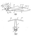
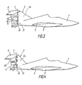
- the fast boat according to the invention has a body 1 (FIG. 1) which is elongated and streamlined, wings 2 with sponson floats 3 which are fastened to the side walls of the body and, attached to the boat stern, a motor 4, for example an outboard motor and a tailplane, consisting of a Ve tikalkiel 5 and a fin 6, the two wing halves 6a and 6 (Fig. 2), which are arranged reversely V-shaped.
- the fin 6 is rigidly attached to the vertical keel 5, which is arranged rotatably about a vertical axis 7 or close to the vertical axis (FIG. 1), which is shown as a dash-dotted line.
- a cavity 8 is provided, in which the outboard motor 4 is housed.
- a thickness of the keel 5 is 15 to 17% of the length of its tendon, whereby a covering of the engine 4 and a required streamline shape of the keel can be created. So that boat stability at a berth and when traveling with small ones Speeds (a displacement) ensured, and the draft is reduced at the rear, is in the lower part of the vertical keel 5 also a buoyancy block 9, the z. B. is made of foam.
- the outboard motor 4 is attached to the transom 10 of the body 1 with the aid of a fastening unit 11 and with the vertical keel 5 by an easily detachable connection 12 (FIG. 2), for. B. bolt, connected so that the axis of rotation 7 (Fig. 1) of the keel is also the axis of rotation of the engine 4.
- the motor axis of rotation does not have to coincide with the axis of rotation of the vertical keel 5, but an additional device is to be installed, with the aid of which rotational movements of the keel and the motor are synchronized.
- the boat construction is simplified.
- the boat also contains a rowing device consisting of a steering wheel 13, which is arranged in the cockpit 14, and rowing lines 15, by means of which the steering wheel 13 is connected to the outboard motor 4 and the vertical keel 5 via openings 16 in the side walls of the body 1.
- the rudder lines are supported against supports 17.
- the angle of the inverted V-shape of the fin 6 is in a relatively wide range from 2 ° to 25 °, preferably from 10 ° to 20 °. Its value is determined by specific aerodynamic characteristics of the speedboat, in particular by the area ratio of the wings 2 and the fin 6, the trim position of the boat, the angle of the V-shape of the wing 2, etc.
- the fin 6 has an arrow shape in plan view, ie ends of its wing halves 6a and 6b are shifted towards the stern with respect to their fastening points on the vertical keel 5.
- this is not a mandatory execution condition of the invention and the wing halves of the fin can be different, e.g. B. be arranged with a zero arrow shape.
- the arrow shape enables an improvement in the operating conditions of the fin and an extension of its power arm, which has a favorable effect on the stability of the boat.
- the cavity 8 in the vertical keel 5 is also not absolutely necessary. In the case when the body 1 in the rear section is sufficiently large and its vertical dimension is comparable to the vertical dimension of the motor, the motor can be mounted under the vertical keel.
- Fig. 3 shows another embodiment variant of the fiction. moderate boat, which differs from the one discussed above in that the vertical keel 5 consists of two parts - an immovable 5a and a 5b rotatable about the axis 7 - the fin 6 being rigidly attached to the rotatable part 5b of the vertical keel.
- This version of the keel 5, in which it is only partially rotatable, is expedient at a high cruising speed of the boat, since then the rotation of only part of the vertical keel ensures the required maneuverability.
- the rotatable part 5b of the vertical keel 5 is hollow in the lower part and the outboard motor 4 is accommodated in this cavity 18.
- the engine 4 can be placed under the rotatable part 5b of the keel (Fig. 4) can be arranged, which is designed without a larger cavity.
- This arrangement of the outboard motor 4 is expedient if the body 1 is at a sufficient height in the stern when the body completely or partially shields the motor from the incoming flow.
- Fig. 5 shows a further embodiment of the boat according to the invention, in which the vertical keel consists of two elements 5c and 5d, which are symmetrical to the central longitudinal plane arranged and attached to side surfaces of the outboard motor 4 by means of easily detachable connections 19.
- the wing half 6a of the fin is connected to the element 5c and the wing half 6b is connected to the element 5d.
- the attachment of the keel elements 5c and 5d to the side surfaces of the engine 4 ensures its good accessibility, although the aerodynamic drag of the boat is increased a little.
- the ⁇ construction shown in Fig. 5 enables the dimensions of the tail unit to be reduced and its control to be facilitated.
- the keel elements 5c and 5d are arranged at an angle to the median longitudinal plane of the boat so that the angle between each of these elements 5c and 5d and the corresponding wing half 6a and 6b of the fin is close to 90 °.
- This arrangement of the keel elements 5c and 5d at an angle to the median longitudinal plane of the boat firstly improves the aerodynamic operating conditions of the vertical keel by ensuring its flow around it by an undisturbed flow, and secondly simplifies the manufacturing technology. of the tail unit and ensures the strength and rigidity of the fin.
- the angle of inclination of the elements 5c and 5d of the keel with respect to the central longitudinal plane of the boat is usually in a range up to 30 °. When the angle of inclination is increased above said value, the aerodynamic effectiveness of the vertical keel decreases.
- sections of the wing halves 6a and 6b of the fin which lie between the elements 5c and 5d of the keel in the region of the central longitudinal plane of the boat, are out solid transparent material, e.g. made of organic glass.
- Another way of making the outboard motor more accessible is to make a longitudinal slot 20 (FIG. 6) in the fin 6.
- the elements 5c and 5d of the vertical keel can also not be attached to the outboard motor, but on a specially designed rotatable element, but this construction is significantly more complicated than that shown in FIGS. 5 and 6 and its use is only expedient, if the boat is equipped with a stationary engine.
- the fin 6 is attached directly to the body 1 so as to be rotatable about the vertical axis 7. If, however, the outboard motor 4 is provided with a flow hood 21 (FIG. 8), the fin 6 is fastened on the flow hood 21. In both cases, the elements 5c and 5d of the vertical keel are attached to the ends of the wing halves 6a and 6b of the fin.
- the fin contains an additional element 6c, which is arranged between the wing halves 6a and 6b.
- This design of the fin helps to prevent the boat from becoming unstable to vibrations.
- the fin with the additional element is attached to a vertical keel consisting of two elements 5c and 5d, it is obvious that this fin is on a keel, which is designed as an element arranged in the central longitudinal plane, on the hull or at the flow hood of ußenbordmotors A, ie in Fig. 1, 3, 4, 7 and 8 illustrated constructions may be appropriate.
- Fig. 1 Fig.
- the motor 4 is a stationary motor which is housed in the body 1 and the boat has an additional hydrodynamic rudder 23 which is arranged in the stern section of the floor and is connected to the rowing device.
- the shaft of the aerodynamic rudder is aligned with the axis of rotation 6 of the vertical keel 5 and the fin 6.
- a buoyancy P (FIG. 12) acts on it, which is the sum of the buoyancy P k acting on the wings 2 and the buoyancy P a , P b acting on the wing halves 6a or 6b the fin act is the same.
- the buoyancy P c balances the weight of the boat and the boat is no longer in contact with water due to sliding surfaces of the body 1 and the sponson float 3.
- the propeller of the motor 4 remains in the water and ensures the required speed.
- the boat according to the invention consequently has that its fin is designed with an inverted V-shape, and in particular when the hydrofoils also have an inverted V-shape, has no such disadvantage because on its windward wing 2 and on the windward wing half of the fin , e.g. the wing half 6a an output and on the leeward wing half 6b an additional lift occurs.
- a heeling moment that arises in the process and acts counter to the wind direction compensates for a large part of the heeling moment that arises as a result of the occurrence of forces on the vertical keel and other boat elements.
- the heeling force acts not only on the inner wing half of the fin relative to the curve, the Wing half 6a, but also the corresponding element 5c of the vertical keel. This additionally increases the heeling moment and improves the maneuverability accordingly of the boat.
- the elements 5c and 5d of the vertical keel of the boat shown in FIGS. 7 and 8 act as aerodynamic end plates, which prevent an overflow of air from the pressure surface of the fin 6 on its suction surface and increase the effectiveness of the fin.
- the optimal size of the inner heel and consequently the required lateral stability and the maneuverability of the boat are determined by appropriate dimensioning of the element surfaces of the tailplane and the wing, their angle of attack, the angle of the V-shape of the fin, the trim position of the boat, etc. when projecting the Bootes ensured.
- the invention can be used in several classes of sports, racing and excursion boats, especially boats with aerodynamic relief (ie those in which the weight of the hull is compensated not only by hydrostatic and hydrodynamic forces but also by air forces during a fast journey) , as well as for the so-called wing-in-ground-effect boats.
- Boats with aerodynamic relief include racing gliding boats and scooters e.g. of classes Rl, R2, OA, OB, OC, OD, ON etc.
Landscapes
- Physics & Mathematics (AREA)
- Fluid Mechanics (AREA)
- Chemical & Material Sciences (AREA)
- Engineering & Computer Science (AREA)
- Combustion & Propulsion (AREA)
- Mechanical Engineering (AREA)
- Ocean & Marine Engineering (AREA)
- Toys (AREA)
- Nitrogen And Oxygen Or Sulfur-Condensed Heterocyclic Ring Systems (AREA)
- Structures Of Non-Positive Displacement Pumps (AREA)
Abstract
Un navire à grande vitesse comporte une coque (1) portant des ailes (2) avec des nageoires à flotteurs (3) et une empennage comprenant une quille verticale (5) et un stabilisateur (6) en forme de V inversé monté avec la possibilité de rotation autour d'un axe vertical (7) au moyen d'un gouvernail (13, 15). Quand le navire tourne, les forces appliquées aux demi-ailes du stabilisateur créent un couple qui fait tourner le navire vers l'intérieur par rapport au virage du navire, par suite de quoi la composante transversale de la force portante aérodynamique empêche la dérive latérale provoquée par les forces centrifuges appliquées sur le navire.
Applications Claiming Priority (2)
| Application Number | Priority Date | Filing Date | Title |
|---|---|---|---|
| SU884450873A SU1756199A1 (ru) | 1988-05-23 | 1988-05-23 | Судно |
| SU4450873 | 1988-05-23 |
Publications (2)
| Publication Number | Publication Date |
|---|---|
| EP0392019A1 true EP0392019A1 (fr) | 1990-10-17 |
| EP0392019A4 EP0392019A4 (en) | 1991-01-09 |
Family
ID=21385672
Family Applications (1)
| Application Number | Title | Priority Date | Filing Date |
|---|---|---|---|
| EP19890906494 Withdrawn EP0392019A4 (en) | 1988-05-23 | 1989-04-20 | High-speed vessel |
Country Status (8)
| Country | Link |
|---|---|
| US (1) | US5029548A (fr) |
| EP (1) | EP0392019A4 (fr) |
| JP (1) | JPH02504379A (fr) |
| AU (1) | AU3739789A (fr) |
| FI (1) | FI900333A7 (fr) |
| GR (1) | GR890100336A (fr) |
| SU (1) | SU1756199A1 (fr) |
| WO (1) | WO1989011414A1 (fr) |
Cited By (1)
| Publication number | Priority date | Publication date | Assignee | Title |
|---|---|---|---|---|
| US6116180A (en) * | 1993-12-16 | 2000-09-12 | Paragon Mann Limited | Boat |
Families Citing this family (6)
| Publication number | Priority date | Publication date | Assignee | Title |
|---|---|---|---|---|
| IT1236113B (it) * | 1989-10-05 | 1993-01-08 | Idroscafo per alte velocita' | |
| US5566775A (en) * | 1992-08-10 | 1996-10-22 | Schoell; Harry | Skirted surface effect vehicle |
| IL121396A (en) | 1997-07-25 | 2000-01-31 | Gaber Benny | Stabilizer for watercraft |
| US7188580B1 (en) * | 2004-07-21 | 2007-03-13 | Borman David L | Variable-geometry graduated surface-foil for wing-in-ground effect vehicles |
| USD713859S1 (en) | 2013-11-15 | 2014-09-23 | Ascento Russell | Boat motor cowling |
| RU2650342C1 (ru) * | 2017-03-29 | 2018-04-11 | Александр Степанович Юнкерт | Летающая лодка (катер-самолет) |
Family Cites Families (10)
| Publication number | Priority date | Publication date | Assignee | Title |
|---|---|---|---|---|
| US3182623A (en) * | 1963-10-28 | 1965-05-11 | Lehmann Guenther Wolfgang | Structure for submarine jet propulsion |
| US3190582A (en) * | 1964-01-02 | 1965-06-22 | Collins Radio Co | Ground effects utilizing and transition aircraft |
| US3288096A (en) * | 1965-09-16 | 1966-11-29 | Armand D Swenson | Hydroplane capable of making stable turns at high speeds |
| FR1591017A (fr) * | 1968-11-08 | 1970-04-20 | ||
| DE1813311B1 (de) * | 1968-12-07 | 1970-07-23 | Lippisch Dr Alexander M | Tragfluegelanordnung fuer ein Fahrzeug zur Bewegung auf dem Lande bzw. dem Wasser und in der Luft |
| GB1450247A (en) * | 1974-02-08 | 1976-09-22 | Dynafoil | Hydrofoil watercraft |
| US3918382A (en) * | 1974-06-24 | 1975-11-11 | Austin Aeromarine Inc | Fixed wing surface effect craft |
| US4237810A (en) * | 1978-12-05 | 1980-12-09 | Westfall Kirk M | Hydrodynamically and aerodynamically designed boat |
| NO150392C (no) * | 1982-05-28 | 1984-10-10 | Paul Kjoelseth | Overflateeffektfartoey |
| US4705234A (en) * | 1985-04-10 | 1987-11-10 | Bourn Ronald L | Ram wing surface effect vehicle |
-
1988
- 1988-05-23 SU SU884450873A patent/SU1756199A1/ru active
-
1989
- 1989-04-20 EP EP19890906494 patent/EP0392019A4/ru not_active Withdrawn
- 1989-04-20 WO PCT/SU1989/000105 patent/WO1989011414A1/fr not_active Ceased
- 1989-04-20 AU AU37397/89A patent/AU3739789A/en not_active Abandoned
- 1989-04-20 US US07/458,673 patent/US5029548A/en not_active Expired - Fee Related
- 1989-04-20 FI FI900333A patent/FI900333A7/fi not_active IP Right Cessation
- 1989-04-20 JP JP1506233A patent/JPH02504379A/ja active Pending
- 1989-05-22 GR GR890100336A patent/GR890100336A/el unknown
Cited By (1)
| Publication number | Priority date | Publication date | Assignee | Title |
|---|---|---|---|---|
| US6116180A (en) * | 1993-12-16 | 2000-09-12 | Paragon Mann Limited | Boat |
Also Published As
| Publication number | Publication date |
|---|---|
| SU1756199A1 (ru) | 1992-08-23 |
| WO1989011414A1 (fr) | 1989-11-30 |
| JPH02504379A (ja) | 1990-12-13 |
| GR890100336A (el) | 1990-03-12 |
| FI900333A0 (fi) | 1990-01-22 |
| EP0392019A4 (en) | 1991-01-09 |
| US5029548A (en) | 1991-07-09 |
| AU3739789A (en) | 1989-12-12 |
| FI900333A7 (fi) | 1990-01-22 |
Similar Documents
| Publication | Publication Date | Title |
|---|---|---|
| EP1313642B1 (fr) | Dispositif de commande pour un cerf-volant de direction sur un bateau | |
| DE69706674T2 (de) | Vortriebs-und steuerelement für schiffe | |
| DE3332868A1 (de) | Bootsschraubenantriebseinheit | |
| EP2161194B1 (fr) | Entrainement d'hélice motorisé pour un bateau | |
| EP1626897A1 (fr) | Gouvernail pour navires | |
| DE3319127A1 (de) | Luftkissenfahrzeug | |
| DE2626422A1 (de) | Schiffs- oder bootssteuerung mit hydrodynamischer servoeinrichtung | |
| DE8237096U1 (de) | Selbsttrimmende segelanordnung | |
| DE68915575T2 (de) | Segler mit einer Anti-Kenter-Hebevorrichtung. | |
| DE2500008C3 (fr) | ||
| DE1039868B (de) | Wasserfahrzeug mit Unterwasser-Laengstragflaechen | |
| DE19624159A1 (de) | Bodeneffektfahrzeug | |
| DE60029767T2 (de) | Antriebsanordnung | |
| DE102019206795B4 (de) | Unterwasserfahrzeug | |
| DE19752170C2 (de) | Im Bugbereich eines mehrrumpfigen Wasserfahrzeugs angeordnete Auftriebsvorrichtung | |
| DE10018573A1 (de) | Wasserfahrzeug | |
| EP0300520B1 (fr) | Bateau rapide | |
| DE19746853C2 (de) | Hochleistungs-Vollschweberuder | |
| DE2848785C2 (de) | Ruderpropeller mit einer Kortdüse für Schiffsantriebe | |
| DE3404588A1 (de) | Vorrichtung zur stabilisierung der wasserlage von segelbooten | |
| AT367696B (de) | Ruder fuer wasserfahrzeuge und schwimmendes geraet | |
| DE10311577A1 (de) | Bugsteuervorrichtung für einen Schubverband | |
| DE3011642C2 (de) | Segelfahrzeug | |
| DE9200773U1 (de) | Tragflächenboot | |
| DE8717355U1 (de) | Einrichtung zur Aufrechterhaltung der Schwimmstabilität von Wasserflugzeugen |
Legal Events
| Date | Code | Title | Description |
|---|---|---|---|
| PUAI | Public reference made under article 153(3) epc to a published international application that has entered the european phase |
Free format text: ORIGINAL CODE: 0009012 |
|
| 17P | Request for examination filed |
Effective date: 19900203 |
|
| AK | Designated contracting states |
Kind code of ref document: A1 Designated state(s): DE FR GB IT SE |
|
| A4 | Supplementary search report drawn up and despatched |
Effective date: 19901120 |
|
| AK | Designated contracting states |
Kind code of ref document: A4 Designated state(s): DE FR GB IT SE |
|
| 17Q | First examination report despatched |
Effective date: 19911212 |
|
| STAA | Information on the status of an ep patent application or granted ep patent |
Free format text: STATUS: THE APPLICATION HAS BEEN WITHDRAWN |
|
| 18W | Application withdrawn |
Withdrawal date: 19911127 |