EP0392111A2 - Bouton décoratif - Google Patents
Bouton décoratif Download PDFInfo
- Publication number
- EP0392111A2 EP0392111A2 EP89307888A EP89307888A EP0392111A2 EP 0392111 A2 EP0392111 A2 EP 0392111A2 EP 89307888 A EP89307888 A EP 89307888A EP 89307888 A EP89307888 A EP 89307888A EP 0392111 A2 EP0392111 A2 EP 0392111A2
- Authority
- EP
- European Patent Office
- Prior art keywords
- plate
- seat plate
- holes
- button
- hole
- Prior art date
- Legal status (The legal status is an assumption and is not a legal conclusion. Google has not performed a legal analysis and makes no representation as to the accuracy of the status listed.)
- Granted
Links
Images


Classifications
-
- A—HUMAN NECESSITIES
- A44—HABERDASHERY; JEWELLERY
- A44B—BUTTONS, PINS, BUCKLES, SLIDE FASTENERS, OR THE LIKE
- A44B1/00—Buttons
- A44B1/18—Buttons adapted for special ways of fastening
- A44B1/22—Buttons adapted for special ways of fastening attached by thread not visible to the front
- A44B1/24—Eye-buttons
-
- A—HUMAN NECESSITIES
- A44—HABERDASHERY; JEWELLERY
- A44B—BUTTONS, PINS, BUCKLES, SLIDE FASTENERS, OR THE LIKE
- A44B1/00—Buttons
- A44B1/04—Ornamental buttons
-
- Y—GENERAL TAGGING OF NEW TECHNOLOGICAL DEVELOPMENTS; GENERAL TAGGING OF CROSS-SECTIONAL TECHNOLOGIES SPANNING OVER SEVERAL SECTIONS OF THE IPC; TECHNICAL SUBJECTS COVERED BY FORMER USPC CROSS-REFERENCE ART COLLECTIONS [XRACs] AND DIGESTS
- Y10—TECHNICAL SUBJECTS COVERED BY FORMER USPC
- Y10T—TECHNICAL SUBJECTS COVERED BY FORMER US CLASSIFICATION
- Y10T24/00—Buckles, buttons, clasps, etc.
- Y10T24/19—Necktie fastener
- Y10T24/199—Ornamental
-
- Y—GENERAL TAGGING OF NEW TECHNOLOGICAL DEVELOPMENTS; GENERAL TAGGING OF CROSS-SECTIONAL TECHNOLOGIES SPANNING OVER SEVERAL SECTIONS OF THE IPC; TECHNICAL SUBJECTS COVERED BY FORMER USPC CROSS-REFERENCE ART COLLECTIONS [XRACs] AND DIGESTS
- Y10—TECHNICAL SUBJECTS COVERED BY FORMER USPC
- Y10T—TECHNICAL SUBJECTS COVERED BY FORMER US CLASSIFICATION
- Y10T24/00—Buckles, buttons, clasps, etc.
- Y10T24/36—Button with fastener
- Y10T24/3651—Separable
-
- Y—GENERAL TAGGING OF NEW TECHNOLOGICAL DEVELOPMENTS; GENERAL TAGGING OF CROSS-SECTIONAL TECHNOLOGIES SPANNING OVER SEVERAL SECTIONS OF THE IPC; TECHNICAL SUBJECTS COVERED BY FORMER USPC CROSS-REFERENCE ART COLLECTIONS [XRACs] AND DIGESTS
- Y10—TECHNICAL SUBJECTS COVERED BY FORMER USPC
- Y10T—TECHNICAL SUBJECTS COVERED BY FORMER US CLASSIFICATION
- Y10T24/00—Buckles, buttons, clasps, etc.
- Y10T24/36—Button with fastener
- Y10T24/3691—Eye shank type button
Definitions
- This invention relates to an ornamental button to be used on clothing, furniture or the like.
- buttons are known including those formed of shell or hard synthetic resin.
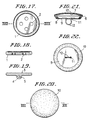
- One of the prior art ornamental buttons is shown in Figs. 17 and 18.
- the button is provided with a plurality of vertical through holes 2 through which a thread is passed.
- a depending projection 4 is formed on the undersurface of the button and the projection is provided with a thread hole 5 through which a thread is passed.
- Figs. 17 and 18 A variety of ornamental buttons are known including those formed of shell or hard synthetic resin.
- the prior art ornamental buttons is shown in Figs. 17 and 18.
- the button is provided with a plurality of vertical through holes 2 through which a thread is passed.
- a depending projection 4 is formed on the undersurface of the button and the projection is provided with a thread hole 5 through which a thread is passed.
- the button is formed of walnut material and comprises a cap-shaped surface seat plate 7 having a peripheral flange 6, a back seat plate 9 having a low upright peripheral flange 8 adapted to fit within the peripheral flange 6 of the surface seat plate 7 and holes 11, a walnut element 10 covering the surface seat plate 7 and a thread attachment ring 12 firmly fitted in the holes 11 against inadvertent detachment from the back seat plate 9.
- buttons have become gorgeous and many of the buttons have been formed of precious metals resulting in high cost buttons.
- the buttons tend to come off the clothing or the like and are lost or get damaged resulting in great loss.
- the thread which sews the button on the clothing has to be cut to remove the button from the clothing prior to cleaning and, after cleaning, the button has to be again sewn on the clothing. The thread cutting and resewing have to be repeated each time cleaning is performed.
- the invention as claimed is intended to remedy this drawback. It solves the problem of how to design an ornamental button which can be simply removed from the clothing, furniture or the like without cutting the thread which sews the button on the clothing by releasably securing the thread attachment ring to the button main body.
- the main advantage offfered by the invention is that the button main body can be detached from the attachment ring, for example prior to cleaning of the clothing on which the ornamental button is sewn, and re-attached as desired without cutting the thread securing the attachment ring.
- the button main body includes a back seat plate having a circular flat bottom with an arcuate guide slot adjacent to the peripheral edge and a holding hole extending radially outwardly from the centre of the bottom and terminating at an enlarged diameter leading end, an operation plate rotatably disposed on the bottom of the back seat plate and provided with an operation projection adjacent to the periphery of the operation seat plate to fit in the guide slot and an operation hole extending radially outwardly from the centre of the operation seat plate and terminating at an enlarged diameter leading end to be aligned with or displaced from the holding hole in the back seat plate on rotation of the operation seat plate, and a spring for urging the operation seat plate against the bottom of the back seat plate, and the thread attachment ring includes a stopper having such a diameter allowed to be inserted via said enlarged diameter leading ends of the holding and operation
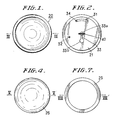
- the ornamental button shown in Figures 1 to 15 of the accompanying drawings comprises a main body 20 and a thread attachment ring 40 releasably secured to the body 20.
- the body 20 includes a back seat plate 21 having a flat circular bottom 22 formed with an arcuate guide slot 31 adjacent to the peripheral edge of the seat plate 21 and a holding hole 33 extending radially outwardly from an inner end 33a at the centre of the bottom 22 and terminating at an enlarged diameter leading or outer end 33b.
- a disc shaped operation seat plate 23 is provided within the body 20 on the bottom 22 of the seat plate 21 and provided with an upwardly extending projection 34 received in the arcuate guide slot 31.
- the operation seat plate 23 is further provided with an operation hole 36 extending radially outwardly from an inner end 36a at the centre of the plate 23 and terminating at an enlarged diameter leading or outer end 36b.
- the hole 36 corresponds to the hole 33 in the back seat plate 21 in shape and coextends with the hole 33.
- the operation seat plate 23 is rotatably disposed on the bottom 22 of the back plate 21 and a spring 24 is provided to bias the operation plate 23 against the bottom 22 to thereby provide the main body 20 of the ornamental button.
- the thread attachment ring 40 can be inserted into the button main body 20 by means of the ends 33b, 36b of the aligned holes 33, 36 in the back seat and operation seat plates 21, 23.
- the ring 40 comprises a head stopper 43 for preventing the coming of the ring 40 off the inner ends 33a, 36a of the slots 33, 36 positioned in the centre of the main body 20, a neck 45 having a thickness to be inserted in the ends 33a, 36a of the holes 33, 36, a shoulder stopper 44 fixedly secured to the neck 45 and a thread guide eye 41 through which a thread is passed.
- the bottom 22 of the back seat plate 21 is provided with a hole 32 and the operation seat plate 23 is provided with an upright projection 35 adapted to fit in the hole 32.
- Body attachment portion 42 of the thread attachment ring 40 includes stopper 43 the diameter of which is smaller than that of the outer ends 33b, 36b.
- stopper 43 of the attachment ring 40 can be inserted into the button main body 20 via the outer ends 33b, 36b of the holes 33, 36.
- the neck 45 is smaller in thickness than the diameter of the inner ends 33a, 36a of the holes 33, 36 positioned in the centres of the back plate bottom 22 and operation seat 23, when stopper 43 is inserted into the hole ends 33b, 36b, the neck 45 can be moved to the centres of the plates 21, 23.
- the button main body 20 can be attached to or detached from the thread attachment ring 40 as the case may be.
- the back seat plate 21 is provided with the hole 32 and the operation seat plate 23 is provided with the projection 35 for fitting in the hole 32.
- the arrangement of the hole 32 and the projection 35 is such that, when the outer ends of the holes 33,36 are moved a predetermined maximum distance away from (Fig. 14) the aligning position (Fig. 15), the projection 34 fits in the hole 32 so that the operation seat plate 23 is prevented from inadvertent rotation.
- the back seat plate 21 is formed of a metal and as shown in Fig. 12, the back seat plate 21 includes an upwardly extending circular flange 28 about the periphery. The lower end portion of the peripheral flange 28 is bent inwardly to provide a shoulder 29 and the above-mentioned bottom 22 is formed in a position below the shoulder 29 by the distance corresponding to the thickness of the above-mentioned operation seat plate 23. As more clearly shown in Fig. 11, the bottom 22 of the back seat plate 21 is formed with the above-mentioned arcuate slot 31 adjacent to and inwardly from the periphery and the above-mentioned small hole 32 spaced circumferentially from the guide slot 31. The hole 33 extends radially outwardly from the semi-circular inner end 33a positioned in the centre of the back seat plate bottom 22 to the semi-circular leading end 33b which has the diameter greater than the width of the hole 33.
- the operation seat plate 23 is a disc having a thickness corresponding to the distance from the upper surface of the bottom 22 to the shoulder 29 of the flange 28 and adapted to rotate on the bottom 22.
- the periphery of the operation seat plate 23 has the manually operable projection 34 arranged to fit in the guide slot 31.
- the projection 35 adapted to fit in the hole 32 is formed by punching.
- the inner end 36a of the operation hole 36 extending radially outwardly from the centre of the operation seat plate 23 has a semi-circle shape of the same diameter as that of the semi-circular end 33a of the holding hole 33 in the back seat plate 21.
- the holes 33, 36 are in the form of slots having the same length and thus, the slots can align with each other.
- the two holes may have the same shape.
- the two holes may take the shape of the hole 33 or 36, but in any case, it is necessary that the dimensions of the inner ends 33a,36a and the outer ends 33b,36b connected by the intermediate portions of the associated slots are chosen to prevent and permit respectively passage of the stopper 43 in the aligning position (Fig. 15).
- the projection 35 has been formed by punching the operation seat plate at the periphery thereof, the projection may be formed by securing a separate member to the operation seat plate 23.
- the washer 25 has been formed by punching an annular piece having a width just sufficient to straddle between the shoulder 29 and the operation seat plate 23 to hold the operation seat plate at the periphery. However, the washer 25 is not an absolutely necessary member.
- the spring 24 is provided for urging the operation seat plate 23 against the bottom 22 of the back seat plate 21 as mentioned hereinabove and in the illustrated embodiment, it is a coiled spring. The spring may be any other type spring.
- the ornamental surface member 26 is formed by warping a disc material downwardly so as to make the diameter of the periphery of the disc substantially equal to that of the inner side of the peripheral upright flange 28 and is retained by turning over the upper end portion of the flange 28.
- Surface member 26 constitutes an important member of the ornamental portion may be of any desired type provided that the size and shape of the periphery of the surface member corresponds to those of the inner side of the upright flange 28.
- the ornamental surface member 26 may bear any desired design. In the illustrated embodiment, although the ornamental surface member functions to hold the spring 24 down, the spring may be held down by another type member.
- the ornamental surface member 26 may be employed for ornamental purpose only. Furthermore, as more clearly shown in the second embodiment in Fig.
- the peripheral edge of the ornamental surface member 26 may be bent downwardly to provide a depending peripheral flange 26a to receive the upright flange 28 of the back seat plate 21 therein and the leading end of the upright flange 28 is caulked against the inner surface of the depending flange 26a of the ornamental surface member 26 to secure the latter.
- the operation seat plate 23 is allowed to rotate within the range wherein the operation projection 34 moves in the guide slot 31.
- the rotation of the operation seat plate 23 is under control with frictional force produced between the back seat plate bottom 22 and the operation seat plate 23 because the operation seat plate 23 is biassed against the bottom 22 by the spring 24.
- the frictional force is produced by the force of the spring 24 and the force is so selected that the operation seat plate is prevented from inadvertent rotation, but allowed to rotate by imparting a certain amount of manual force to the operation projection 34.
- the projection 35 is fitted in the hole 32, the projection 35 is subjected to the force of the spring 24 to maintain the engagement and, unless a force greater than the force of the spring 24 is applied to the operation projection 34, the operation seat plate 23 does not rotate. Once released, the operation seat plate 23 can be rotated under control by the above-mentioned frictional force.
- the thread attachment ring 40 shown in Fig. 13 is detachably attached to the button main body 20 described hereinabove.
- the thread attachment ring 40 includes the thread guide eye 41 through which a thread is passed and attachment portion 42 for securing to the body 20.
- the attachment portion 42 includes the pair of disc shaped opposing stoppers 43, 44 and the neck 45 connecting between the stoppers 43, 44.
- the diameter of the stopper 43 is greater than that of the inner ends 33a, 36a of the holes 33, 36 and slightly smaller than that of the outer ends 33b, 36b of the holes 33, 36.
- the neck 45 is in the form of a bar having the diameter smaller than that of the inner ends 33a, 36a of the holes 33, 36.
- the diameter of the stopper 44 may be equal to or larger than that of the stopper 43.
- the length of the neck 45 is longer than the thickness of the combined thickness of the operation seat plate 23 and the bottom 22 of the back seat plate 21 so as to pinch the back seat and operation seat plates by the stoppers 43, 44.
- the operation seat plate 23 is rotate by moving the operation projection 34 in the guide slot 31 in one direction so as to align the holding hole 33 and operation hole 36 and more particularly align the outer ends 33b, 36b of the holes 33, 36 with each other as shown in Fig. 15.
- the stopper 43 on the body attachment portion 42 is inserted through the aligned outer ends 33b, 36b of the holes 33, 36 whereupon the ring 40 is moved to the inner ends 33a, 36a of the holes.
- the operation projection 34 is then moved in the opposite direction within the guide slot 31.
- the operation seat plate 23 rotates in the opposite direction so as to displace the operation hole 36 with respect to the holding hole 33 as shown in Fig. 14.
- the neck 45 of the thread attachment ring 40 is within the aligned inner ends 33a, 36a.
- the thread attachment ring 40 is prevented from inadvertently getting out of the holes 33, 36 because the diameter of the stopper 43 is greater than the diameter of the inner ends 33a, 36a of the holes 33, 36.
- the button main body 20 can be removed from the clothing leaving the thread attachment ring 40 sewn on the clothing. After the cleaning operation, the main body can be simply replaced to the ring 40.
- the main body 20 can be simply attached to the clothing and detached from the clothing leaving the thread attachment ring 40 sewn on the clothing.
- the cumbersome operations experienced in cleaning of the clothing on which the prior art buttons are sewn such as removing the button from the clothing by cutting off the thread which sews the button on the clothing and after the cleaning, resewing the button onto the clothing can be eliminated.
- the operation seat plate by means of which the button main body is attached to the thread attachment ring is urged against the bottom of the back seat plate under the force of the spring, the operation seat plate is always braked by the spring.
- the operation seat plate is prevented from rotating inadvertently and inadvertent detachment of the main body from the thread attachment ring is prevented.
- the possibility of inadvertent detachment of the main body can be further reduced by the provision of the projection 35 to fit in hole 32.
Landscapes
- Slide Fasteners, Snap Fasteners, And Hook Fasteners (AREA)
Applications Claiming Priority (2)
| Application Number | Priority Date | Filing Date | Title |
|---|---|---|---|
| JP89610/89 | 1989-04-11 | ||
| JP1089610A JPH02268702A (ja) | 1989-04-11 | 1989-04-11 | 飾り釦 |
Publications (3)
| Publication Number | Publication Date |
|---|---|
| EP0392111A2 true EP0392111A2 (fr) | 1990-10-17 |
| EP0392111A3 EP0392111A3 (en) | 1990-10-31 |
| EP0392111B1 EP0392111B1 (fr) | 1993-05-19 |
Family
ID=13975520
Family Applications (1)
| Application Number | Title | Priority Date | Filing Date |
|---|---|---|---|
| EP89307888A Expired - Lifetime EP0392111B1 (fr) | 1989-04-11 | 1989-08-03 | Bouton décoratif |
Country Status (4)
| Country | Link |
|---|---|
| US (1) | US4926527A (fr) |
| EP (1) | EP0392111B1 (fr) |
| JP (1) | JPH02268702A (fr) |
| DE (1) | DE68906671T2 (fr) |
Cited By (4)
| Publication number | Priority date | Publication date | Assignee | Title |
|---|---|---|---|---|
| GB2311456B (en) * | 1996-03-28 | 2000-10-18 | Michael Lawrence Mcgeary | Complementary clothing accessory |
| FR2890542A1 (fr) * | 2005-09-13 | 2007-03-16 | Estelle Ferragu | Bijoux amovibles pour textiles |
| CN105231599A (zh) * | 2015-11-09 | 2016-01-13 | 江苏红豆实业股份有限公司 | 大小可调节的纽扣 |
| CN105231598A (zh) * | 2015-11-09 | 2016-01-13 | 江苏红豆实业股份有限公司 | 可调式纽扣 |
Families Citing this family (14)
| Publication number | Priority date | Publication date | Assignee | Title |
|---|---|---|---|---|
| JPH09140413A (ja) * | 1995-11-27 | 1997-06-03 | Meiko Sangyo Kk | 釦の装着治具、装着治具の取付具および装着方法 |
| USD626231S1 (en) | 2005-06-10 | 2010-10-26 | Angio Dynamics, Inc. | Surgical button |
| USD605075S1 (en) * | 2008-11-12 | 2009-12-01 | Universal Trim Supply Co., Ltd. | Garment fastener with a surface pattern |
| USD605078S1 (en) * | 2008-11-12 | 2009-12-01 | Universal Trim Supply Co., Ltd. | Garment fastener with a surface pattern |
| USD605077S1 (en) * | 2008-11-12 | 2009-12-01 | Universal Trim Supply Co., Ltd. | Garment fastener with a surface pattern |
| USD605076S1 (en) * | 2008-11-12 | 2009-12-01 | Universal Trim Supply Co., Ltd. | Garment fastener with a surface pattern |
| USD605074S1 (en) * | 2008-11-12 | 2009-12-01 | Universal Trim Supply Co., Ltd. | Garment fastener with a surface pattern |
| USD605079S1 (en) * | 2008-11-18 | 2009-12-01 | Universal Trim Supply Co., Ltd. | Garment fastener with a surface pattern |
| US8522404B2 (en) * | 2009-03-19 | 2013-09-03 | Danny Matei | Button assembly |
| US20110056049A1 (en) * | 2009-09-08 | 2011-03-10 | Rice Jason W | Button assembly with detachable button cover |
| US10165811B2 (en) * | 2012-01-27 | 2019-01-01 | The Cozmix Inc. | Interchangeable fabric accessory and method of use |
| USD793903S1 (en) * | 2017-02-21 | 2017-08-08 | Capitol Industrial Design Llc | Button adapter |
| CN109480397A (zh) * | 2018-11-29 | 2019-03-19 | 颍上县艺豪服饰辅料有限公司 | 一种新型衣服扣 |
| CN110192694B (zh) * | 2019-07-16 | 2021-08-10 | 赵艳 | 一种旋压扣 |
Family Cites Families (15)
| Publication number | Priority date | Publication date | Assignee | Title |
|---|---|---|---|---|
| BE480356A (fr) * | ||||
| US373128A (en) * | 1887-11-15 | cables | ||
| FR506088A (fr) * | 1919-11-06 | 1920-08-13 | Ernest Vouillamoz | Système de bouton mécanique |
| US2214030A (en) * | 1939-04-08 | 1940-09-10 | Joseph L Pereles | Button |
| CH242680A (de) * | 1945-01-19 | 1946-05-31 | Wirth Paul | Mehrteiliger Knopf. |
| FR947981A (fr) * | 1947-05-12 | 1949-07-19 | Friedrich Wilhelm Schulte G M | Bouton de vêtement recouvert d'étoffe |
| FR1375507A (fr) * | 1963-11-26 | 1964-10-16 | Schmidt Staub & Co | Bouton de manchette à plaquette décorative |
| US3439439A (en) * | 1966-09-06 | 1969-04-22 | Raleigh B Stimson | Decorative button assembly |
| US3583039A (en) * | 1969-01-21 | 1971-06-08 | James W Walker | Changeable clothing button structure |
| JPS5299004U (fr) * | 1976-01-22 | 1977-07-26 | ||
| US4471510A (en) * | 1982-11-22 | 1984-09-18 | Derosa Alfred C | Two piece interchangeable button |
| NZ203886A (en) * | 1983-04-14 | 1987-04-30 | New Zealand Dev Finance | Button assembly includes washer which tapers towards its peripheral rim |
| JPS638243Y2 (fr) * | 1984-10-02 | 1988-03-12 | ||
| JPS6163909U (fr) * | 1984-10-03 | 1986-05-01 | ||
| JPH0354566Y2 (fr) * | 1985-10-22 | 1991-12-03 |
-
1989
- 1989-04-11 JP JP1089610A patent/JPH02268702A/ja active Granted
- 1989-08-02 US US07/388,466 patent/US4926527A/en not_active Expired - Fee Related
- 1989-08-03 DE DE89307888T patent/DE68906671T2/de not_active Expired - Fee Related
- 1989-08-03 EP EP89307888A patent/EP0392111B1/fr not_active Expired - Lifetime
Cited By (6)
| Publication number | Priority date | Publication date | Assignee | Title |
|---|---|---|---|---|
| GB2311456B (en) * | 1996-03-28 | 2000-10-18 | Michael Lawrence Mcgeary | Complementary clothing accessory |
| FR2890542A1 (fr) * | 2005-09-13 | 2007-03-16 | Estelle Ferragu | Bijoux amovibles pour textiles |
| CN105231599A (zh) * | 2015-11-09 | 2016-01-13 | 江苏红豆实业股份有限公司 | 大小可调节的纽扣 |
| CN105231598A (zh) * | 2015-11-09 | 2016-01-13 | 江苏红豆实业股份有限公司 | 可调式纽扣 |
| CN105231598B (zh) * | 2015-11-09 | 2017-10-27 | 江苏红豆实业股份有限公司 | 可调式纽扣 |
| CN105231599B (zh) * | 2015-11-09 | 2017-10-27 | 江苏红豆实业股份有限公司 | 大小可调节的纽扣 |
Also Published As
| Publication number | Publication date |
|---|---|
| EP0392111A3 (en) | 1990-10-31 |
| DE68906671D1 (de) | 1993-06-24 |
| EP0392111B1 (fr) | 1993-05-19 |
| JPH02268702A (ja) | 1990-11-02 |
| US4926527A (en) | 1990-05-22 |
| DE68906671T2 (de) | 1993-11-25 |
| JPH059081B2 (fr) | 1993-02-04 |
Similar Documents
| Publication | Publication Date | Title |
|---|---|---|
| EP0392111B1 (fr) | Bouton décoratif | |
| US4982581A (en) | Coupling device for ornamental piece | |
| US5501089A (en) | Key fob and attachment | |
| US7228651B1 (en) | Holder for an identification card | |
| US3141211A (en) | Ornamental button | |
| US20030098323A1 (en) | Removable belt clip | |
| US6192708B1 (en) | Finger ring insert | |
| US3500507A (en) | Button assembly | |
| US4610058A (en) | Central lock for safety belts | |
| US6079419A (en) | Non-visible clip for head covering | |
| US4283815A (en) | Button construction | |
| US4751771A (en) | Button | |
| US2764853A (en) | Mounting head for grinding polishing, and featheredging tools | |
| EP0469454A1 (fr) | Bouton à rivet | |
| HK65991A (en) | Button cover with spring means | |
| US4040148A (en) | Button for clothes | |
| US2065940A (en) | Key holder | |
| HRP20010087A2 (en) | A device for coupling an item of footwear on an item of sports equipment | |
| US6568573B2 (en) | Wristwatch case with interchangeable bracelet | |
| US2206052A (en) | Bracelet end connection | |
| US2502034A (en) | Separable button | |
| JP3040156U (ja) | 携帯電話機のホルダ | |
| US3905189A (en) | Mechanical improvement on an alarm clock | |
| KR101924194B1 (ko) | 자동버클용 벨트 고정장치 | |
| JPS6348194Y2 (fr) |
Legal Events
| Date | Code | Title | Description |
|---|---|---|---|
| PUAI | Public reference made under article 153(3) epc to a published international application that has entered the european phase |
Free format text: ORIGINAL CODE: 0009012 |
|
| PUAL | Search report despatched |
Free format text: ORIGINAL CODE: 0009013 |
|
| AK | Designated contracting states |
Kind code of ref document: A2 Designated state(s): DE FR GB |
|
| AK | Designated contracting states |
Kind code of ref document: A3 Designated state(s): DE FR GB |
|
| 17P | Request for examination filed |
Effective date: 19901228 |
|
| 17Q | First examination report despatched |
Effective date: 19920210 |
|
| GRAA | (expected) grant |
Free format text: ORIGINAL CODE: 0009210 |
|
| AK | Designated contracting states |
Kind code of ref document: B1 Designated state(s): DE FR GB |
|
| REF | Corresponds to: |
Ref document number: 68906671 Country of ref document: DE Date of ref document: 19930624 |
|
| ET | Fr: translation filed | ||
| PLBE | No opposition filed within time limit |
Free format text: ORIGINAL CODE: 0009261 |
|
| STAA | Information on the status of an ep patent application or granted ep patent |
Free format text: STATUS: NO OPPOSITION FILED WITHIN TIME LIMIT |
|
| 26N | No opposition filed | ||
| PGFP | Annual fee paid to national office [announced via postgrant information from national office to epo] |
Ref country code: GB Payment date: 19960730 Year of fee payment: 8 |
|
| PGFP | Annual fee paid to national office [announced via postgrant information from national office to epo] |
Ref country code: FR Payment date: 19960731 Year of fee payment: 8 |
|
| PGFP | Annual fee paid to national office [announced via postgrant information from national office to epo] |
Ref country code: DE Payment date: 19961015 Year of fee payment: 8 |
|
| PG25 | Lapsed in a contracting state [announced via postgrant information from national office to epo] |
Ref country code: GB Free format text: LAPSE BECAUSE OF NON-PAYMENT OF DUE FEES Effective date: 19970803 |
|
| GBPC | Gb: european patent ceased through non-payment of renewal fee |
Effective date: 19970803 |
|
| PG25 | Lapsed in a contracting state [announced via postgrant information from national office to epo] |
Ref country code: FR Free format text: LAPSE BECAUSE OF NON-PAYMENT OF DUE FEES Effective date: 19980430 |
|
| PG25 | Lapsed in a contracting state [announced via postgrant information from national office to epo] |
Ref country code: DE Free format text: LAPSE BECAUSE OF NON-PAYMENT OF DUE FEES Effective date: 19980501 |
|
| REG | Reference to a national code |
Ref country code: FR Ref legal event code: ST |