EP0392148A2 - Raccord de tuyaux - Google Patents
Raccord de tuyaux Download PDFInfo
- Publication number
- EP0392148A2 EP0392148A2 EP90102452A EP90102452A EP0392148A2 EP 0392148 A2 EP0392148 A2 EP 0392148A2 EP 90102452 A EP90102452 A EP 90102452A EP 90102452 A EP90102452 A EP 90102452A EP 0392148 A2 EP0392148 A2 EP 0392148A2
- Authority
- EP
- European Patent Office
- Prior art keywords
- pipe connection
- connection according
- pipe
- sections
- sealing elements
- Prior art date
- Legal status (The legal status is an assumption and is not a legal conclusion. Google has not performed a legal analysis and makes no representation as to the accuracy of the status listed.)
- Granted
Links
Images

Classifications
-
- F—MECHANICAL ENGINEERING; LIGHTING; HEATING; WEAPONS; BLASTING
- F16—ENGINEERING ELEMENTS AND UNITS; GENERAL MEASURES FOR PRODUCING AND MAINTAINING EFFECTIVE FUNCTIONING OF MACHINES OR INSTALLATIONS; THERMAL INSULATION IN GENERAL
- F16L—PIPES; JOINTS OR FITTINGS FOR PIPES; SUPPORTS FOR PIPES, CABLES OR PROTECTIVE TUBING; MEANS FOR THERMAL INSULATION IN GENERAL
- F16L21/00—Joints with sleeve or socket
- F16L21/002—Sleeves or nipples for pipes of the same diameter; Reduction pieces
- F16L21/005—Sleeves or nipples for pipes of the same diameter; Reduction pieces made of elastic material, e.g. partly or completely surrounded by clamping devices
Definitions
- the invention relates to a pipe connection according to the preamble of claim 1.
- Pipe connections are known in manifold forms and have a design that corresponds to the operating conditions of the pipelines. They also differ, among other things, in the respective manufacturing and assembly costs and the complexity, in particular in the handling by the customer.
- the production of a pipe connection for example by screwing, is comparatively labor-intensive and also requires the provision of pipes, the wall thickness of which, taking into account the thread to be attached, must be thicker than is required by the operating conditions of the pipeline. This point of view applies to both steel and plastic pipes. In the case of a screw connection, the required wall thickness is usually determined by the thread certainly. If, on the other hand, the pipe connection is made by welding two pipe ends, relatively thin-walled pipes can be used under otherwise unchanged conditions. However, the production of welded joints is also comparatively labor-intensive.
- the coupling consists essentially of a core tube intended for insertion into both sleeve-like expansions, which has special sealing elements on the outside, the latter, however, not only serving as a sealing function, but also serving for the form-fitting fastening of the tube ends to one another, in particular the tube connection having the necessary strength with respect to an axial one Give impingement.
- the sealing elements mentioned are provided with bulges which lead to the ela tical intervention in the bulged portions of the opposite pipe ends are determined.
- the coupling piece is formed in one piece, so that in particular the on-site handling of this pipe connection turns out to be very simple.
- the material used in the sealing elements is selected according to the operating conditions of the pipeline, the radial elasticity of the coupling piece being controllable to a certain extent via the material side in connection with the dimensioning of the sealing elements, but also of the core tube, so that even with comparatively larger ones Nominal sizes of the pipeline, the plug connection can be produced with comparatively little effort.
- the exact design of the sleeve-like widening, in particular the bulged section thereof, is basically arbitrary.
- the bulged section tapers in the direction of the front end of the respective pipe end, so that a positive connection can be produced in connection with a bulge of the sealing element corresponding to this section.
- the bulged section can have a tulip-shaped profile.
- this is a cylindrical section which has radial or conical indentations at the end.
- the features of claim 2 bring a particularly simple and clear design of the coupling piece with it.
- Said receiving pockets which are arranged in the bulges of the sealing elements, produce a certain radial elasticity of the sealing elements, which in the rest of the design are largely modeled on the inner contour of the bulged sections of the widening of the pipe ends.
- the receiving pockets mentioned can be used very advantageously as receiving spaces for filling compounds which are introduced into them during assembly are used and stabilization, in particular to increase the strength of the pipe connection.
- the coupling piece is fundamentally symmetrical with respect to a radial central plane, ie there are similar sealing elements on both end regions of the core tube, which expediently end at a distance from the aforementioned central plane.
- the sealing elements preferably consist of a rubber-elastic material.
- the features of claim 4 ensure that there are no electrochemical corrosion problems when using metallic materials within the pipe connection according to the invention.
- the core tube can very advantageously be provided with an axially continuous slot.
- the features of claims 5 to 7 relate to the detailed design or purpose of the receiving pockets.
- the filler to be introduced into this is expediently a plastic that can be connected or glued to the material of the sealing elements, the design of this plastic determining whether the resulting pipe connection is designed to be detachable, conditionally detachable or unsolvable. If, for example, a thermosetting plastic is introduced into these receiving pockets, the pipe connection can be regarded as unsolvable, since the hardened plastic due to the positive engagement between the bulges of the sealing element and the corresponding sections of the pipe ends prevents pulling apart. When using a thermoplastic, however, the connection can be released by introducing heat. A release is also possible if the plastic is comparatively soft, so that the positive engagement can be released with comparatively little effort with corresponding elastic deformation of the sealing element.
- the features of claim 8 are used to set the smoothest possible inner wall in the area of the pipe connection.
- the medium flowing within this pipeline thus does not experience any turbulence in the area of the pipe connection, so that there are no flow noises.
- areas are avoided in this area, which lead to deposits, so that the pipe connection according to the invention can be used safely, particularly from a hygienic point of view, in the context of drinking water pipes.
- claims 9 and 10 serve to further increase the strength of the pipe connection, both in the radial and in the axial direction.
- the two arched sections of the sleeve-like expansions of the pipe ends, which overlap and secure the clamping element of the pipe clamp, ensure a particularly reliable design, which is also easy to handle on site.
- the tensioning body in its inner profile is adapted at least at its front end regions to the profile of the curved sections, so that an identical one is distributed over them - and indeed over a comparatively large area moderate pressure is applied.
- the features of claim 11 serve to further increase the sealing effect of the pipe connection according to the invention, which is expedient under certain operating conditions. This is the case, for example, if increased corrosion resistance to certain influences present in the ground is required, the penetration of which into the pipe connection must be prevented in any case. Examples include buried heating oil pipes or pressurized dirty water pipes, but also compressed air pipes in aggressive indoor air, cooling water pipes or fire extinguishing pipes. In these cases, different material requirements are imposed on the sealant effective against the medium being conveyed than on the sealant acting against the environment.
- the protrusion thus provided on the inside of the tensioning body and assuming an additional sealing function is expediently glued to the inside of the tensioning body.
- the annular space closed off on the outside by the clamping body in accordance with the features of claim 12 hereafter serves as a receiving space for the volume of filling material displaced from the receiving pockets as a result of the insertion of the coupling piece into the sleeve-like widenings. This is distributed evenly in the said annular space, so that a uniform hydraulic pressure is exerted on the outer sides of the sleeve-like expansions within the annular space by tensioning the pipe clamp. In this way, a reliable seal and at the same time a high strength of the pipe connection is contributed.
- the core tube and the two tube ends can also consist of a suitable plastic.
- the pipe connection according to the invention can in principle be designed as described above.
- the basic ideas of the pipe connection according to the invention can also be applied when a pipe end is only cylindrical.
- a sealing element must be applied to this, the outer profile of which corresponds to the sealing element described above, which is provided with a corresponding ring-like receiving pocket, which in turn is open in the opposite direction to the direction of insertion and serves to accommodate a filling compound which is partially displaced during insertion .
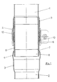
- 1, 2 in the drawings denote two pipe ends to be connected or connected, the two end regions of which are each widened in the same manner in the manner of a sleeve.
- the exemplary embodiment shown is in each case steel pipe ends.
- Each of the sleeve-like expansions mentioned consists of a first, essentially cylindrical section 3, to which - in the direction of the front end of the tube ends - a tulip-like in longitudinal section Section 4 follows. Most of the latter section 4 is expanded in diameter with respect to the cylindrical section 3, but tapers towards its free end on the end face to a diameter which essentially corresponds to the diameter of the cylindrical section 3.
- a coupling piece designated generally by reference number 5, is used.
- the latter consists of a metallic, cylindrically shaped core tube 6, which at the same time forms part of the inner wall of the coupling piece 5.
- the core tube 6 carries at both end regions, a ring-like sealing element 7 which surrounds this on the outside and which can consist of an elastic, for example rubber-like material.
- the sealing element 7 projects with its one end section 8 toward the end of the core tube 6 facing it and the core tube is integrated into the substance of the sealing element 7 such that the inner wall of the end section 8 is aligned with the inner wall of the core tube 6.
- the sealing element 7 On its end facing away from the end section 8, the sealing element 7 in turn has a tulip-like widening 9, which at its front end forms an annular receiving pocket 10 which is radially delimited by the outside of the core tube and the inside of the sealing element. This receiving pocket 10 is open at its front end.
- the sealing element 7 is glued or vulcanized to the outside of the core tube 6 in a central section 11. It is essential that the entire inner wall of the coupling piece 5 forms an essentially uniform surface, ie a surface free of joints.
- the core tube 6 is preferably provided with a longitudinal slot, not shown in the drawing, which gives it a certain radial elasticity.
- a hardenable plastic for example, is introduced into the receiving pockets 10 of the coupling piece 5, so that when the coupling piece 5 is inserted into the sleeve-like widening of the one pipe end there is a certain diameter reduction of the respective sealing element 7, which in turn has a displacement effect on the liquid plastic located in the respective ring-like receiving pocket 10, which is displaced in this way out of the receiving pocket 10 and onto the outside of the tulip-like section 4.
- Fig. 1 shows an assembly state in which the coupling piece 5 is fully inserted into the pipe end 1, the pipe end 2 is still to be pushed over the coupling piece 5.
- the sections 12 of the sealing elements 7 surrounding the receiving pockets 10 on the outside are securely pressed against the inside of the tulip-like section 4, and thus a reliable sealing effect in this area.
- the tulip-like sections 4 also form a reliable, form-fitting fixation of the pipe ends 1, 2 to one another.
- the releasability of the pipe connection according to the invention essentially depends only on the nature of the plastic introduced into the receiving pockets 10. If this is a thermoset material, a non-destructive solution of this pipe connection is not possible. If this is an elastomeric material, the pipe connection can be released using heat. If this is an easily deformable plastic, the pipe connection can also be considered in the borderline case as a pure plug-in connection, which can be detached at any time.
- a screw-operated pipe clamp known per se which, in the assembled state, overlaps both tulip-like sections 4, i.e. with sleeve-like clamping bodies 14 arranged at the ends and adapted to the profile of the sections 4 and provided with radial indentations, the diameter of which can be reduced in a manner known per se.
- this clamping body an additional safeguard against an axial pulling apart of the pipe connection can be realized, in particular with larger dimensions and larger pressures.
- annular space 15 results between the inner surface of the clamping body 14 and the outer surfaces of the sections 4, which is available as a receiving space for the plastic displaced from the receiving pockets 10 is available.
- a reduction in the diameter of the tensioning body 14 of the pipe clamp 13 thus results in a uniform radial application of pressure on the outer sides of the tulip-like sections 4 that delimit this annular space via this plastic located in the annular space 15.
- a major advantage of the pipe connection according to the invention is that there are practically no joints or other receiving spaces in the course of the inner wall between the pipe ends 1, 2, which could cause flow noises and, moreover, could involve hygienic risks when using the pipe connection as part of a drinking water pipe.
- the core tube 6, the tube ends 1, 2 and the tube clamp 13 are made of identical metallic materials.
Landscapes
- Engineering & Computer Science (AREA)
- General Engineering & Computer Science (AREA)
- Mechanical Engineering (AREA)
- Non-Disconnectible Joints And Screw-Threaded Joints (AREA)
- Joints With Sleeves (AREA)
- Rigid Pipes And Flexible Pipes (AREA)
- Extrusion Moulding Of Plastics Or The Like (AREA)
- Mutual Connection Of Rods And Tubes (AREA)
Applications Claiming Priority (2)
| Application Number | Priority Date | Filing Date | Title |
|---|---|---|---|
| DE8904526U | 1989-04-11 | ||
| DE8904526U DE8904526U1 (de) | 1989-04-11 | 1989-04-11 | Rohrverbindung |
Publications (3)
| Publication Number | Publication Date |
|---|---|
| EP0392148A2 true EP0392148A2 (fr) | 1990-10-17 |
| EP0392148A3 EP0392148A3 (fr) | 1991-04-10 |
| EP0392148B1 EP0392148B1 (fr) | 1992-10-28 |
Family
ID=6838162
Family Applications (1)
| Application Number | Title | Priority Date | Filing Date |
|---|---|---|---|
| EP90102452A Expired - Lifetime EP0392148B1 (fr) | 1989-04-11 | 1990-02-08 | Raccord de tuyaux |
Country Status (4)
| Country | Link |
|---|---|
| EP (1) | EP0392148B1 (fr) |
| AT (1) | ATE81898T1 (fr) |
| DE (2) | DE8904526U1 (fr) |
| DK (1) | DK0392148T3 (fr) |
Families Citing this family (2)
| Publication number | Priority date | Publication date | Assignee | Title |
|---|---|---|---|---|
| DE4040638C2 (de) * | 1990-01-20 | 1996-07-04 | Karl Heinz Vahlbrauk | Rohrverbindung |
| DE9308116U1 (de) * | 1993-05-29 | 1993-07-15 | Vahlbrauk, Karl Heinz, 3353 Bad Gandersheim | Rohrverbindung |
Family Cites Families (8)
| Publication number | Priority date | Publication date | Assignee | Title |
|---|---|---|---|---|
| DE453910C (de) * | 1925-05-26 | 1927-12-21 | Reginald William Spencer | Rohrkupplung |
| US2323823A (en) * | 1942-07-10 | 1943-07-06 | Pollak Mfg Company | Joint for exhaust manifold systems |
| AT178506B (de) * | 1951-01-10 | 1954-05-25 | Karl Ludwig Lanninger | Weitabwinkelbare Rohr-Schnellkupplung |
| US3633947A (en) * | 1970-02-20 | 1972-01-11 | Corning Glass Works | Coupling |
| US3656771A (en) * | 1970-12-11 | 1972-04-18 | Irrigation Accessories Co | Flexible seal assembly for spigot and bell conduit joint |
| FR2206828A5 (fr) * | 1972-11-15 | 1974-06-07 | Lepelley Robert | |
| EP0043304B1 (fr) * | 1980-06-27 | 1984-05-30 | Regie Nationale Des Usines Renault | Dispositif de filtration des vibrations du moteur |
| US4465309A (en) * | 1981-08-13 | 1984-08-14 | Umac, Inc. | Connecting or repair device |
-
1989
- 1989-04-11 DE DE8904526U patent/DE8904526U1/de not_active Expired
-
1990
- 1990-02-08 DK DK90102452.1T patent/DK0392148T3/da active
- 1990-02-08 DE DE9090102452T patent/DE59000386D1/de not_active Expired - Lifetime
- 1990-02-08 EP EP90102452A patent/EP0392148B1/fr not_active Expired - Lifetime
- 1990-02-08 AT AT90102452T patent/ATE81898T1/de not_active IP Right Cessation
Also Published As
| Publication number | Publication date |
|---|---|
| ATE81898T1 (de) | 1992-11-15 |
| EP0392148B1 (fr) | 1992-10-28 |
| DK0392148T3 (da) | 1993-02-22 |
| DE59000386D1 (de) | 1992-12-03 |
| DE8904526U1 (de) | 1989-05-18 |
| EP0392148A3 (fr) | 1991-04-10 |
Similar Documents
| Publication | Publication Date | Title |
|---|---|---|
| DE69002721T2 (de) | Rohrverbindung. | |
| DE19740144A1 (de) | Verbindung eines Metallrohres mit einer Metallhülse | |
| DE69607803T2 (de) | Rohrkupplung | |
| DE3602499A1 (de) | Kupplungsnippel | |
| EP1046855B1 (fr) | Raccord rapide | |
| DE69703431T3 (de) | Rohrpressverbindung | |
| DE60020212T2 (de) | Rohrverbindungselement, insbesondere für kunststoffrohre | |
| DE602004001133T2 (de) | Vorrichtung zur verbindung einer fluidzirkulationsleitung mit einem feuerfesten element | |
| DE2938366A1 (de) | Stossfugendichtung fuer fertigbauteile aus beton oder stahlbeton | |
| CH621646A5 (fr) | ||
| DE69602925T2 (de) | Rohrkupplung und verfahren zum verbinden eines rohres an einem verbindungsstück | |
| DE2513982C3 (de) | Rohrdichtung | |
| EP0392148B1 (fr) | Raccord de tuyaux | |
| DE2158068C3 (de) | Schlauchanschlußstück für Hochdruckschläuche | |
| DE3231858A1 (de) | Endfitting fuer schlaeuche | |
| DE20219600U1 (de) | Pressverbindungsanordnung und Halteelement für eine Pressverbindung | |
| EP1462702B1 (fr) | Raccord de tuyaux avec un tuyau déformé | |
| DE19943473B4 (de) | Dichtungsvorrichtung | |
| DE4137495C2 (de) | Rohrverbindung für Druckrohre | |
| DE10331381A1 (de) | Pressverbindung und Stützhülse für eine Pressverbindung | |
| DE2412697A1 (de) | Rohrverbindung | |
| DE1970807U (de) | Schlauchfassung. | |
| DE69912149T2 (de) | Verbindungsvorrichtung einer metallischen rohrleitung | |
| DE2234632C3 (de) | Schlaucharmatur für Hochdruckschläuche | |
| EP0472056A1 (fr) | Element de raccord pour tuyaux |
Legal Events
| Date | Code | Title | Description |
|---|---|---|---|
| PUAI | Public reference made under article 153(3) epc to a published international application that has entered the european phase |
Free format text: ORIGINAL CODE: 0009012 |
|
| AK | Designated contracting states |
Kind code of ref document: A2 Designated state(s): AT DE DK FR GB NL SE |
|
| PUAL | Search report despatched |
Free format text: ORIGINAL CODE: 0009013 |
|
| RHK1 | Main classification (correction) |
Ipc: F16L 27/04 |
|
| AK | Designated contracting states |
Kind code of ref document: A3 Designated state(s): AT DE DK FR GB NL SE |
|
| 17P | Request for examination filed |
Effective date: 19910502 |
|
| 17Q | First examination report despatched |
Effective date: 19911030 |
|
| GRAA | (expected) grant |
Free format text: ORIGINAL CODE: 0009210 |
|
| AK | Designated contracting states |
Kind code of ref document: B1 Designated state(s): AT DE DK FR GB NL SE |
|
| REF | Corresponds to: |
Ref document number: 81898 Country of ref document: AT Date of ref document: 19921115 Kind code of ref document: T |
|
| GBT | Gb: translation of ep patent filed (gb section 77(6)(a)/1977) | ||
| REF | Corresponds to: |
Ref document number: 59000386 Country of ref document: DE Date of ref document: 19921203 |
|
| ET | Fr: translation filed | ||
| REG | Reference to a national code |
Ref country code: DK Ref legal event code: T3 |
|
| PLBE | No opposition filed within time limit |
Free format text: ORIGINAL CODE: 0009261 |
|
| STAA | Information on the status of an ep patent application or granted ep patent |
Free format text: STATUS: NO OPPOSITION FILED WITHIN TIME LIMIT |
|
| 26N | No opposition filed | ||
| EAL | Se: european patent in force in sweden |
Ref document number: 90102452.1 |
|
| PGFP | Annual fee paid to national office [announced via postgrant information from national office to epo] |
Ref country code: SE Payment date: 19960118 Year of fee payment: 7 |
|
| PG25 | Lapsed in a contracting state [announced via postgrant information from national office to epo] |
Ref country code: SE Effective date: 19970209 |
|
| EUG | Se: european patent has lapsed |
Ref document number: 90102452.1 |
|
| REG | Reference to a national code |
Ref country code: GB Ref legal event code: IF02 |
|
| PGFP | Annual fee paid to national office [announced via postgrant information from national office to epo] |
Ref country code: AT Payment date: 20090219 Year of fee payment: 20 Ref country code: DK Payment date: 20090220 Year of fee payment: 20 |
|
| PGFP | Annual fee paid to national office [announced via postgrant information from national office to epo] |
Ref country code: DE Payment date: 20090227 Year of fee payment: 20 Ref country code: NL Payment date: 20090223 Year of fee payment: 20 |
|
| PGFP | Annual fee paid to national office [announced via postgrant information from national office to epo] |
Ref country code: GB Payment date: 20090223 Year of fee payment: 20 |
|
| PGFP | Annual fee paid to national office [announced via postgrant information from national office to epo] |
Ref country code: FR Payment date: 20090217 Year of fee payment: 20 |
|
| REG | Reference to a national code |
Ref country code: DK Ref legal event code: EUP |
|
| REG | Reference to a national code |
Ref country code: GB Ref legal event code: PE20 Expiry date: 20100207 |
|
| NLV7 | Nl: ceased due to reaching the maximum lifetime of a patent |
Effective date: 20100208 |
|
| PG25 | Lapsed in a contracting state [announced via postgrant information from national office to epo] |
Ref country code: GB Free format text: LAPSE BECAUSE OF EXPIRATION OF PROTECTION Effective date: 20100207 |
|
| PG25 | Lapsed in a contracting state [announced via postgrant information from national office to epo] |
Ref country code: DE Free format text: LAPSE BECAUSE OF EXPIRATION OF PROTECTION Effective date: 20100208 |