EP0392185A1 - Automatische Orbitanalyse mit Anwendung eines Neuronnetzwerkes - Google Patents
Automatische Orbitanalyse mit Anwendung eines Neuronnetzwerkes Download PDFInfo
- Publication number
- EP0392185A1 EP0392185A1 EP90104186A EP90104186A EP0392185A1 EP 0392185 A1 EP0392185 A1 EP 0392185A1 EP 90104186 A EP90104186 A EP 90104186A EP 90104186 A EP90104186 A EP 90104186A EP 0392185 A1 EP0392185 A1 EP 0392185A1
- Authority
- EP
- European Patent Office
- Prior art keywords
- shaft
- deflection
- equipment
- recited
- neural network
- Prior art date
- Legal status (The legal status is an assumption and is not a legal conclusion. Google has not performed a legal analysis and makes no representation as to the accuracy of the status listed.)
- Granted
Links
Images

Classifications
-
- G—PHYSICS
- G01—MEASURING; TESTING
- G01M—TESTING STATIC OR DYNAMIC BALANCE OF MACHINES OR STRUCTURES; TESTING OF STRUCTURES OR APPARATUS, NOT OTHERWISE PROVIDED FOR
- G01M1/00—Testing static or dynamic balance of machines or structures
- G01M1/14—Determining imbalance
- G01M1/16—Determining imbalance by oscillating or rotating the body to be tested
- G01M1/22—Determining imbalance by oscillating or rotating the body to be tested and converting vibrations due to imbalance into electric variables
Definitions
- the present invention is generally related to a system for detecting defects in equipment having a rotating shaft and, more particularly, to a system using a neural network performing orbit analysis to detect such defects.
- One type of analysis uses sensors to detect vibration of the equipment, specifically the shaft, and analyzes the vibration.
- One of the simplest analyses of this type is to detect changes in the vibration components which are harmonics of the running speed. If the shaft is rubbing, several harmonics of the running speed will be present. If there is only a high amplitude of the first harmonic, then the shaft needs balancing. More sophisticated frequency analysis can be performed to detect other defects or malfunctions in the equipment.
- orbit analysis Another known analysis technique is orbit analysis.
- orbit analysis movement of the axis of the shaft from a normal position is detected.
- the pattern of movement, when viewed from the end of the shaft can be analyzed to provide information regarding type of defect.
- the pattern is produced by mounting a pair of deflection sensors adjacent to a shaft bearing to detect deflection along X (horizontal) and Y (vertical) axes. Signals produced by the deflection sensors are used as inputs to an oscilloscope to produce an orbit plot.
- FIGs. 1A-1D Examples of some typical orbit plots which are produced by defects in equipment are illustrated in Figs. 1A-1D.
- a typical example of an orbit plot associated with a severe case of misalignment is illustrated in Fig. 1A.
- An example of an orbit plot produced by oil whirl or oil whip in a sleeve bearing is illustrated in Fig. 1B.
- the spiked circle illustrated in Fig. 1C is an example of the orbit plot produced by a rub
- the plot illustrated in Fig. 1D is an example of a bent or unbalanced shaft.
- the orientation and extent of deviation from a circle may change.
- An object of the present invention is to provide an automated system for performing orbit analysis.
- Another object of the present invention is to produce a diagnosis of malfunctions in equipment having a rotating shaft using both orbit analysis and frequency analysis.
- the invention in its broad form resides in a method and a system for automatically performing orbit analysis in equipment having a rotating shaft to detect a malfunction by way of movement in the shaft-axis, comprising: input means for inputting movement data indicative of movement of the shaft; characterized by a neural network system for processing the movement data using a trained neural network to produce a first malfunction-indication of the equipment.
- a system for automatically analyzing equipment having a rotating shaft, for defects, comprising input means for inputting movement data indicative of movement of the shaft and a neural network system for processing the movement data using a trained neural network to produce a first defect indication of the shaft bearing system.
- the movement data can be produced using deflection sensors capable of sensing deflection of the shaft along each of two axes perpendicular to each other and substantially normal to the surface of the shaft.
- deflection sensors capable of sensing deflection of the shaft along each of two axes perpendicular to each other and substantially normal to the surface of the shaft.
- at least two of the deflection sensors are preferably associated with each of the bearings.
- the same deflection sensors can be used to generate frequency data analyzed to obtain a second defect indication.
- an expert system rulebase is used to analyze the first and second defect indications to obtain a diagnosis of the equipment.
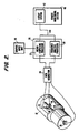
- a neural network is used for the purpose of analyzing the orbit of a rotating shaft 10 in a piece of equipment 12.
- the equipment may be of any type and is generically illustrated by the cylinder 12 in Fig. 2.
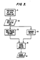
- the method used to recognize equipment malfunctions using orbit analysis will be described with reference to Fig. 3, and a specific system using this method will be described with reference to Fig. 2.
- the first step in using any neural network is to define the object or objects to be recognized. In some of the older neural networks, this was done manually in a form of programming using weights at each of the nodes in the network. Most modern neural networks have a training mode in which the data to be recognized is input and the proper output to be produced is supplied. Conceptually, this is similar to teaching a child to speak or read where an answer is given and corrected.
- the key to proper training of the neural network is in the data which is selected for training. Patterns which are easily recognized as an example of an object, or in this case a defect, should be supplied and some guidance should be provided in distinguishing between less extreme examples.
- the plots illustrated in Figs. 1A-1D might be used as part of the training for a neural network to recognize equipment malfunctions which result in the illustrated orbit plots illustrated in Figs. 1A-1D.
- a graphic input unit 20 may be used for inputting the training data to a neuro-computing processor 22 regardless of whether the source of the data is orbit plots from malfunctioning equipment or synthetic data. Use of the graphic input unit 20 is preferred to obtaining the training data directly from the X-Y probes 14, 16 via a data acquisition system 24, because there is greater control over the data which is supplied.
- the training data is preferably stored in a memory (not shown) of a computing system 26 associated with the neuro-computing processor 22. This enables the neuro-computing processor to be retrained and the same training data to be used to train other neuro-computing processors without reentering the data.
- the training data may be updated when new orbit plots are discovered or improvements to the neural network are desired.
- the neural network formed in the neuro-computing processor 22 can be used to perform orbit analysis.
- X-Y deflection data is input 28 via either the graphic input unit 20 or data acquisition system 24.
- the graphic input unit 20 may be a mouse, a digitizing tablet, or any other known device foc inputting graphical data.
- a high resolution touch screen could be mounted over an oscilloscope displaying an orbit and a stylus could be used to trace the outline of the orbit. This may be satisfactory for a relatively stationary and consistent orbit like that illustrated in Fig. 1D, but more erratic orbits, like that illustrated in Fig.
- 1C would be more difficult to input, even if the oscilloscope stores a plot corresponding to a single rotation of the shaft.
- a similar technique would be to use a camera to obtain a photograph of the oscilloscope display from conventional orbit analysis equipment and then input the photographed orbit using a digitizing tablet or mouse.
- the neuro-computing processor 22 is connected on-line to the data acquisition system 24 which obtains movement data from the X-Y probes or deflection sensors 14, 16.
- the data acquisition system 24 obtains movement data from the X-Y probes or deflection sensors 14, 16.
- a typical piece of equipment has several bearings and deflection sensors may be mounted near each of the bearings or at alternative locations along the shaft.
- the deflection sensors may be of any known type, such as proximity sensors or vibration sensors.
- a key phasor sensor 30 is preferably used to allow determination of phase angle during rotation of the shaft 10. This enables the deflection data output by the deflection sensors 14, 16 to be referenced to the rotation of the shaft 10.
- the key phasor sensor 30 can also be used to provide speed information in addition to timing for the deflection data.
- the data obtained by the data acquisition system 24 indicates deflection of the axis of the shaft 10 from a normal position.
- This movement data is processed by the neuro-computing processor 22 which performs orbit analysis 32 using the neural network created by the training data.
- the result of the orbit analysis will be termed a defect indication.
- This indication may, of course, be that no defect has been detected. This would correspond to an orbit plot of a dot or small circle, indicating that the axis of the shaft 10 remains substantially centered.
- the defect indication may represent a defect in the shaft, such as being bent or unbalanced, or a malfunction elsewhere in the equipment which, e.g., has caused a rub.
- the size of the plot e.g., along the major and minor axes of an ellipse like that illustrated in Fig. 1D; the orientation of the orbit, e.g., the angle between the major axes of an ellipse and the X axis; and the shape of the orbit are some of the distinguishing features, as illustrated in Figs. 1A-1D.
- the direction of the orbit in comparison to the direction of rotation of the shaft is also a factor which must be considered by the neuro-computing processor 22. Therefore, data supplied to the neuro-computing processor 22 must include not only the pattern produced by the orbit, but also orientation information, scaling information and whether the center of the shaft moves in the same direction as the surface of the shaft, or counter to it. In other words, if the shaft when viewed from one end is rotating clockwise, data must be provided indicating whether the axis of the shaft, when viewed from the same end, appears to move in a clockwise or counterclockwise direction.
- orbit analysis used alone is a powerful tool for diagnosing defects or malfunctions in a piece of equipment
- orbit analysis is used in combination with frequency analysis 34.
- deflection data 28 is inputted to a frequency analysis processor 38, e.g., via the data acquisition system 24.
- a separate vibration sensor is not illustrated in Fig. 2. It may be mounted on the exterior of the equipment 12, e.g., where the phase sensor 30 is illustrated, or in the interior of the equipment 12, in any conventional manner.
- the frequency analysis processor 38 may perform conventional analysis, including overall vibration (amplitude and phase) and variation in the harmonics of the running speed of the equipment 12.
- the frequency analysis 34 results in a second indication of defects or malfunctions which can be compared with the indication produced by the orbit analysis. Thus, it can be determined whether the defect indications produced by the orbit analysis and the frequency analysis are cumulative or contradictory.
- expert system analysis 40 performed by an expert system 42.
- An example of an expert system which has been used for diagnosing indications generated by on line sensors is provided in U.S. Patent No. 4,644,479.
- the output from the expert system analysis 40 is a diagnosis 44 of the operating conditions in the equipment 12.
- the neuro-computing processor 22 and frequency analysis processor 38 are closely associated in computing system 26 and may share some devices, such as memory, input/output ports, operator interface, etc.
- the computing system 26 is preferably connected on-line to the sensors 14, 16, 30 via the data acquisition system 24 at the same site as the equipment 12 which is being monitored. Relatively close proximity of the computing system 26 and equipment 12 is desirable, since a relatively large amount of high frequency data is required for the analyses 32 and 34.
- the defect indications generated by the processors 22 and 30 may be transmitted via a communication link 46 to a remote monitoring system 48 which includes the expert system 42.
- the expert system 42 may be included in the computing system 26. If expert system analysis 40 is considered unnecessary, the defect indications produced by orbit analysis 32 may be used with or without additional frequency analysis 34.
- the neuro-computing processor 22 is not connected on-line to the equipment 12. Instead, deflection data is input via the graphic input unit 20 and another man/machine interface, such as a keyboard (not shown) which is used to provide, e.g., scaling information.
- the orbit plot input via the graphic input unit 20 may be generated as a sketch from an oscilloscope screen or by digitizing a photograph, as discussed above with reference to the input of training data. It should be noted that some neuro-computing processors are capable of generating a compiled program which can be executed in a conventional computer which could then be used to perform the orbit analysis 32.
Landscapes
- Physics & Mathematics (AREA)
- General Physics & Mathematics (AREA)
- Testing Of Devices, Machine Parts, Or Other Structures Thereof (AREA)
- Measurement Of Mechanical Vibrations Or Ultrasonic Waves (AREA)
Applications Claiming Priority (2)
| Application Number | Priority Date | Filing Date | Title |
|---|---|---|---|
| US32213789A | 1989-03-13 | 1989-03-13 | |
| US322137 | 1989-03-13 |
Publications (2)
| Publication Number | Publication Date |
|---|---|
| EP0392185A1 true EP0392185A1 (de) | 1990-10-17 |
| EP0392185B1 EP0392185B1 (de) | 1993-01-13 |
Family
ID=23253596
Family Applications (1)
| Application Number | Title | Priority Date | Filing Date |
|---|---|---|---|
| EP90104186A Expired - Lifetime EP0392185B1 (de) | 1989-03-13 | 1990-03-05 | Automatische Orbitanalyse mit Anwendung eines Neuronnetzwerkes |
Country Status (4)
| Country | Link |
|---|---|
| EP (1) | EP0392185B1 (de) |
| CN (1) | CN1047387A (de) |
| DE (1) | DE69000749T2 (de) |
| ES (1) | ES2036856T3 (de) |
Cited By (2)
| Publication number | Priority date | Publication date | Assignee | Title |
|---|---|---|---|---|
| EP0628798A1 (de) * | 1993-06-07 | 1994-12-14 | SCHENCK RoTec GmbH | Verfahren zum Ausblenden nicht relevanter Messwerte bei einem Unwuchtmesssignal |
| DE19506471A1 (de) * | 1995-02-24 | 1996-08-29 | Roland Schuehle | Verfahren und Vorrichtung zur elektronischen Bestimmung und Kontrolle der Güte der Ausrichtung aneinandergekuppelter Wellen |
Families Citing this family (3)
| Publication number | Priority date | Publication date | Assignee | Title |
|---|---|---|---|---|
| NL1024372C2 (nl) * | 2003-09-24 | 2005-03-29 | Skf Ab | Werkwijze en sensoropstelling voor belastingmeting op een lager met rollend element gebaseerd op modale vervorming. |
| CN106197851B (zh) * | 2016-07-19 | 2018-12-14 | 江苏大学 | 一种悬臂式多级离心泵轴心轨迹测量装置及方法 |
| EP3795975B1 (de) * | 2018-06-14 | 2023-08-02 | Mitsubishi Electric Corporation | Anomalieerfassungsvorrichtung, anomalieerfassungsverfahren und anomalieerfassungsprogramm |
Citations (2)
| Publication number | Priority date | Publication date | Assignee | Title |
|---|---|---|---|---|
| EP0066494A1 (de) * | 1981-05-21 | 1982-12-08 | Societe Nationale Elf Aquitaine | Analytisches System mit optischer Anzeige von Vibrationsbewegungen einer Maschine mit rotierendem Teil |
| US4453407A (en) * | 1980-04-17 | 1984-06-12 | Hitachi, Ltd. | Vibration diagnosis method and apparatus for rotary machines |
-
1990
- 1990-03-05 EP EP90104186A patent/EP0392185B1/de not_active Expired - Lifetime
- 1990-03-05 ES ES90104186T patent/ES2036856T3/es not_active Expired - Lifetime
- 1990-03-05 DE DE1990600749 patent/DE69000749T2/de not_active Expired - Fee Related
- 1990-03-07 CN CN 90101207 patent/CN1047387A/zh active Pending
Patent Citations (2)
| Publication number | Priority date | Publication date | Assignee | Title |
|---|---|---|---|---|
| US4453407A (en) * | 1980-04-17 | 1984-06-12 | Hitachi, Ltd. | Vibration diagnosis method and apparatus for rotary machines |
| EP0066494A1 (de) * | 1981-05-21 | 1982-12-08 | Societe Nationale Elf Aquitaine | Analytisches System mit optischer Anzeige von Vibrationsbewegungen einer Maschine mit rotierendem Teil |
Non-Patent Citations (4)
| Title |
|---|
| APPLIED OPTICS * |
| MACHINE DESIGN * |
| MEASUREMENT CONTROL * |
| NATURE * |
Cited By (3)
| Publication number | Priority date | Publication date | Assignee | Title |
|---|---|---|---|---|
| EP0628798A1 (de) * | 1993-06-07 | 1994-12-14 | SCHENCK RoTec GmbH | Verfahren zum Ausblenden nicht relevanter Messwerte bei einem Unwuchtmesssignal |
| DE19506471A1 (de) * | 1995-02-24 | 1996-08-29 | Roland Schuehle | Verfahren und Vorrichtung zur elektronischen Bestimmung und Kontrolle der Güte der Ausrichtung aneinandergekuppelter Wellen |
| DE19506471C2 (de) * | 1995-02-24 | 1999-10-21 | Roland Schuehle | Verfahren zur elektronischen Bestimmung und Kontrolle der Güte der Ausrichtung aneinandergekuppelter Wellen und Vorrichtung zu dessen Durchführung |
Also Published As
| Publication number | Publication date |
|---|---|
| DE69000749T2 (de) | 1993-04-29 |
| CN1047387A (zh) | 1990-11-28 |
| DE69000749D1 (de) | 1993-02-25 |
| ES2036856T3 (es) | 1993-06-01 |
| EP0392185B1 (de) | 1993-01-13 |
Similar Documents
| Publication | Publication Date | Title |
|---|---|---|
| CA1159562A (en) | Vibration diagnosing method and apparatus for a rotary machine | |
| KR101748559B1 (ko) | 회전체 진단 장치 및 방법 | |
| JPH10176949A5 (de) | ||
| Uhlmann et al. | Condition monitoring in the cloud | |
| US7079959B2 (en) | High-resolution intelligent rotor machine diagnostic system and method | |
| CN111912361A (zh) | 表面测量仪 | |
| JP2002268728A (ja) | 同期診断監視システム、同期診断監視装置、および同期診断監視プログラム | |
| EP0392185B1 (de) | Automatische Orbitanalyse mit Anwendung eines Neuronnetzwerkes | |
| CN111521259B (zh) | 磨机检测方法、装置与设备 | |
| EP2597437A1 (de) | Verfahren zur Beurteilung des technischen Zustands einer Drehwelle | |
| CN117740242A (zh) | 动力涡轮机动平衡测试系统 | |
| Murty et al. | Compressor Health monitoring using IOT | |
| RU2123923C1 (ru) | Способ диагностики токарных станков по параметрам точности и устройство для его осуществления | |
| KR100220084B1 (ko) | 다축포터블스캐너를 이용한 간이 자동초음파 탐상장치구조 | |
| KR102858044B1 (ko) | 베어링의 결함 진단 방법 | |
| US4393690A (en) | Force balancing techniques for complex cyclically moving planar linkages | |
| Alekseev et al. | Data measurement system of compressor units defect diagnosis by vibration value | |
| JPS63167222A (ja) | 回転機械の異常診断装置 | |
| CN118981668B (zh) | 一种便携式旋转类设备故障诊断仪及诊断方法 | |
| RU2803036C1 (ru) | Прибор для автоматической поверки индикаторов часового типа и измерительных головок с применением машинного зрения | |
| JP2657172B2 (ja) | 水車発電機の軸振れ測定方法及び測定装置 | |
| JP2010169421A (ja) | ジンバルのマスアンバランス測定装置および方法 | |
| JPH0450731A (ja) | 回転機故障診断システム | |
| CN107966176A (zh) | 基于数据挖掘算法的机电液混合设备实时故障诊断装置 | |
| JPH07260564A (ja) | 回転機器の異常診断装置及び方法 |
Legal Events
| Date | Code | Title | Description |
|---|---|---|---|
| PUAI | Public reference made under article 153(3) epc to a published international application that has entered the european phase |
Free format text: ORIGINAL CODE: 0009012 |
|
| AK | Designated contracting states |
Kind code of ref document: A1 Designated state(s): CH DE ES GB IT LI SE |
|
| 17P | Request for examination filed |
Effective date: 19901228 |
|
| 17Q | First examination report despatched |
Effective date: 19910925 |
|
| ITF | It: translation for a ep patent filed | ||
| GRAA | (expected) grant |
Free format text: ORIGINAL CODE: 0009210 |
|
| AK | Designated contracting states |
Kind code of ref document: B1 Designated state(s): CH DE ES GB IT LI SE |
|
| PG25 | Lapsed in a contracting state [announced via postgrant information from national office to epo] |
Ref country code: SE Effective date: 19930113 |
|
| REF | Corresponds to: |
Ref document number: 69000749 Country of ref document: DE Date of ref document: 19930225 |
|
| REG | Reference to a national code |
Ref country code: ES Ref legal event code: FG2A Ref document number: 2036856 Country of ref document: ES Kind code of ref document: T3 |
|
| PLBE | No opposition filed within time limit |
Free format text: ORIGINAL CODE: 0009261 |
|
| STAA | Information on the status of an ep patent application or granted ep patent |
Free format text: STATUS: NO OPPOSITION FILED WITHIN TIME LIMIT |
|
| 26N | No opposition filed | ||
| PGFP | Annual fee paid to national office [announced via postgrant information from national office to epo] |
Ref country code: GB Payment date: 19980209 Year of fee payment: 9 |
|
| PGFP | Annual fee paid to national office [announced via postgrant information from national office to epo] |
Ref country code: ES Payment date: 19980323 Year of fee payment: 9 |
|
| PGFP | Annual fee paid to national office [announced via postgrant information from national office to epo] |
Ref country code: DE Payment date: 19980330 Year of fee payment: 9 |
|
| PGFP | Annual fee paid to national office [announced via postgrant information from national office to epo] |
Ref country code: CH Payment date: 19980415 Year of fee payment: 9 |
|
| PG25 | Lapsed in a contracting state [announced via postgrant information from national office to epo] |
Ref country code: GB Free format text: LAPSE BECAUSE OF NON-PAYMENT OF DUE FEES Effective date: 19990305 |
|
| PG25 | Lapsed in a contracting state [announced via postgrant information from national office to epo] |
Ref country code: ES Free format text: LAPSE BECAUSE OF EXPIRATION OF PROTECTION Effective date: 19990306 |
|
| PG25 | Lapsed in a contracting state [announced via postgrant information from national office to epo] |
Ref country code: LI Free format text: LAPSE BECAUSE OF NON-PAYMENT OF DUE FEES Effective date: 19990331 Ref country code: CH Free format text: LAPSE BECAUSE OF NON-PAYMENT OF DUE FEES Effective date: 19990331 |
|
| GBPC | Gb: european patent ceased through non-payment of renewal fee |
Effective date: 19990305 |
|
| REG | Reference to a national code |
Ref country code: CH Ref legal event code: PL |
|
| PG25 | Lapsed in a contracting state [announced via postgrant information from national office to epo] |
Ref country code: DE Free format text: LAPSE BECAUSE OF NON-PAYMENT OF DUE FEES Effective date: 20000101 |
|
| REG | Reference to a national code |
Ref country code: ES Ref legal event code: FD2A Effective date: 20010601 |
|
| PG25 | Lapsed in a contracting state [announced via postgrant information from national office to epo] |
Ref country code: IT Free format text: LAPSE BECAUSE OF NON-PAYMENT OF DUE FEES;WARNING: LAPSES OF ITALIAN PATENTS WITH EFFECTIVE DATE BEFORE 2007 MAY HAVE OCCURRED AT ANY TIME BEFORE 2007. THE CORRECT EFFECTIVE DATE MAY BE DIFFERENT FROM THE ONE RECORDED. Effective date: 20050305 |