EP0392303A1 - Dispositif d'éclairage chirurgical - Google Patents
Dispositif d'éclairage chirurgical Download PDFInfo
- Publication number
- EP0392303A1 EP0392303A1 EP90106245A EP90106245A EP0392303A1 EP 0392303 A1 EP0392303 A1 EP 0392303A1 EP 90106245 A EP90106245 A EP 90106245A EP 90106245 A EP90106245 A EP 90106245A EP 0392303 A1 EP0392303 A1 EP 0392303A1
- Authority
- EP
- European Patent Office
- Prior art keywords
- arm
- operating
- spring arm
- boom
- light according
- Prior art date
- Legal status (The legal status is an assumption and is not a legal conclusion. Google has not performed a legal analysis and makes no representation as to the accuracy of the status listed.)
- Withdrawn
Links
- 125000006850 spacer group Chemical group 0.000 claims abstract description 10
- 238000010276 construction Methods 0.000 abstract 1
- 230000003287 optical effect Effects 0.000 abstract 1
- 239000000725 suspension Substances 0.000 description 3
- 230000005611 electricity Effects 0.000 description 1
Images


Classifications
-
- F—MECHANICAL ENGINEERING; LIGHTING; HEATING; WEAPONS; BLASTING
- F21—LIGHTING
- F21V—FUNCTIONAL FEATURES OR DETAILS OF LIGHTING DEVICES OR SYSTEMS THEREOF; STRUCTURAL COMBINATIONS OF LIGHTING DEVICES WITH OTHER ARTICLES, NOT OTHERWISE PROVIDED FOR
- F21V21/00—Supporting, suspending, or attaching arrangements for lighting devices; Hand grips
- F21V21/14—Adjustable mountings
- F21V21/26—Pivoted arms
- F21V21/28—Pivoted arms adjustable in more than one plane
-
- F—MECHANICAL ENGINEERING; LIGHTING; HEATING; WEAPONS; BLASTING
- F21—LIGHTING
- F21W—INDEXING SCHEME ASSOCIATED WITH SUBCLASSES F21K, F21L, F21S and F21V, RELATING TO USES OR APPLICATIONS OF LIGHTING DEVICES OR SYSTEMS
- F21W2131/00—Use or application of lighting devices or systems not provided for in codes F21W2102/00-F21W2121/00
- F21W2131/20—Lighting for medical use
- F21W2131/205—Lighting for medical use for operating theatres
Definitions
- the invention relates to an operating room lamp comprising a flange tube and at least one arm rotatable about its longitudinal axis, a spacer, a spring arm, a bracket and a lamp body with at least one lamp and associated optics.
- the structure and size of surgical lights are determined by the intended use and the spatial conditions. In order to cover the demand, the manufacturers have to stock a large number of surgical light variants, which are manufactured individually. This can result in unnecessary inventory or bottlenecks in the delivery of certain surgical light configurations.
- Constructional difficulties can also arise if e.g. luminaire bodies that are not constructed symmetrically are used to ensure that they are easily placed in the desired position for illuminating an operating field.
- an inclined arm can run between the spring arm and the extension arm. This is horizontal and the spring arm can be pivoted in a vertical plane containing the longitudinal axis of the inclined arm. This results in a large space requirement.
- the object of the present invention is, inter alia, to design an operating light of the type mentioned at the outset in such a way that a There is a high degree of variation without the number of desired variants having to have a corresponding number of surgical light types. Easy positioning is also possible, in particular in the case of multi-light operating lights, without the suspension having a disruptive effect. Finally, a small space requirement should be required, in particular in the case of multi-light operating lights comprising an inclined arm.
- the object is essentially achieved in that at least the flange tube, the boom, the spacer and the spring arm each consist of pre-assembled parts of element groups in order to achieve a desired structure of the operating light.
- a plurality of identically constructed connecting pieces which in turn have different lengths, can optionally be arranged on the flange tube.
- an interchangeable stop ring interacting with the flange tube can be used in the connection piece to limit the rotation of the boom. This means that one and the same boom, depending on the presence of the stop ring, is limited in its rotation or is endlessly rotatable.
- the vertically running plane in which the spring arm can only be pivoted, intersects a further vertically running plane, in which the longitudinal axis of the inclined arm runs, which in turn is pivotable about a vertical axis.
- This allows the spring arm to a extent be raised so that it can be pivoted into a horizontal plane receiving the inclined arm. Inclined arm and spring arm can therefore be arranged side by side.
- the spring arm has an end section which is angled to its longitudinal axis.
- the lamp body can be rotated by more than 360 ° to the 1/4 bracket leading to this, so that any desired positioning and thus a close approach of the lamp body to the Operation field is possible without having to move the entire suspension.
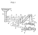
- FIG. 1 shows an operating light arrangement (10) which comprises two operating lights (10) and (12) and a light guide arrangement (14) which is aligned with an operating field.
- Both the operating lights (10) and (12) and the light guide arrangement (14) together with a flange tube (18) extending from a ceiling (16) consist of prefabricated and stocked element groups.
- Booms (20), (22) and (24) extend from the flange tube (18) and, with respect to the operating light (12) and the light guide arrangement (14), via intermediate pieces (26) and (28) with spring arms (30 ) or (32) are connected, which in turn are connected to the light guide (40) or the lamp bodies (42) via a 1/4 bracket or two 1/4 brackets (36) and (38).
- the multi-light operating light (10) also has an inclined arm (48).
- a 1/4 bracket (52) leads from the spring arm, which has an angled end section (50), to the lamp body (54).
- the essential parts are pre-assembled so that they would be interchangeable with regard to the element groups.
- the spring arms (30) and (32) or the intermediate pieces (26) and (28) are interchangeable due to the same connecting elements.
- the boom (22) can also replace the boom (20) if it is completely removed from the arrangement according to FIG. 1.
- Fig. 2 is a plan view of an operating light (56) is shown, the one extending from a flange tube, not shown, in the drawing plane pivotable arm (58), a pivotable perpendicular to this spacer, also tiltable in the drawing plane (60), a vertical comprises a spring arm (62) which can be pivoted about the axis (76), a 1/4 bracket (64) which can be pivoted perpendicular to the plane and a lamp body (68) which can be pivoted about the axis (66).
- the above-described elements consequently provide a gimbal-mounted suspension of the lamp body (68). This results in an optimal range of motion and easy mobility in any direction.
- the longitudinal axis (70) of the spring arm (62) which is not pivotable about a vertical axis, does not run parallel to the longitudinal axis of the inclined arm (16) provided with the reference symbol (72). Rather, they describe an angle so that the spring arm (62) can be pivoted in a horizontal plane receiving the inclined arm (60). The latter results in a space saving, which in turn means that the operating light (56) does not impair the movement space of an operating team.
- the longitudinal axis (70) of the spring arm (62) can be seen to run in a first vertical plane which intersects the vertical plane in which the longitudinal axis (72) of the inclined arm (60) runs.
- the spring arm (62) has an end section (74) which is angled outwards with respect to the inclined arm (60).
- FIG 3 and 4 are sectional views of a flange tube (78), which is connected on the ceiling side via a bushing (80) to an outer tube (82), one of which is connected to e.g. a flange connectable flange (84).
- brackets (86) and (88) are arranged on the flange tube (78), which extend the flange tube (78) have surrounding identically constructed connectors (90) and (92). The same applies to the diameter of the arms (86) and (88). These themselves are supported against the flange tube (78) by means of bearings (94) and (96), for example.
- the electrical connections are made via electrical connections (98) and (100) running within the flange tube (78), which in turn are connected to slip rings (102) and (104) present in the brackets (86) and (88), and from there to supply the operating lights with electricity within the outriggers, spacers, inclined arms, spring arms and 1/4 brackets.
- annular recesses are provided in each connection piece (106) or (108) towards the flange tube (78), one of which two are provided by way of example with the reference numbers (110) and (112).
- a stop ring (114) which is connected to the flange tube (78) can be inserted into the cutout (110) or (112).
- a projection extends from the stop ring (114) in the direction of the section of the connecting piece receiving the stop ring (114) and can interact with a projection extending from the section and running in the direction of the stop ring (114). The section can be rotated around the flange tube and thus the stop ring in one circumference until the projections abut one another.
- a connection between a 1/4 bracket (116) and a lamp body (118) is shown, through which this can be rotated by more than 360 °.
- a pin (120) extends from the 1/4 bracket (116) and extends into a sleeve (122) extending from the lamp body (118). The sleeve and bolt are supported against each other by bearings (124) and (126).
- a stop ring (132) is arranged between the inner end face (128) of the pin (120) and the facing bottom face (130) of the sleeve, which faces (134) and (()) in the end face (128) and the bottom face (130) 136) one each Circular section has the following recess (138) or (140) into which a protruding from the pin (120) or the sleeve (122) protrudes such as bolts (142) or (144).
- the recesses (138) and (140) are offset from one another, so that this results in a rotation of the lamp body (118) to the pin (120) by more than 360 °, provided that the recesses (138) and (140) one Circle segment follows, which is larger than ⁇ .
Landscapes
- Engineering & Computer Science (AREA)
- General Engineering & Computer Science (AREA)
- Fastening Of Light Sources Or Lamp Holders (AREA)
- Non-Portable Lighting Devices Or Systems Thereof (AREA)
Applications Claiming Priority (2)
| Application Number | Priority Date | Filing Date | Title |
|---|---|---|---|
| DE8903956U DE8903956U1 (de) | 1989-03-31 | 1989-03-31 | Operationsleuchte |
| DE8903956U | 1989-03-31 |
Publications (1)
| Publication Number | Publication Date |
|---|---|
| EP0392303A1 true EP0392303A1 (fr) | 1990-10-17 |
Family
ID=6837713
Family Applications (1)
| Application Number | Title | Priority Date | Filing Date |
|---|---|---|---|
| EP90106245A Withdrawn EP0392303A1 (fr) | 1989-03-31 | 1990-03-31 | Dispositif d'éclairage chirurgical |
Country Status (2)
| Country | Link |
|---|---|
| EP (1) | EP0392303A1 (fr) |
| DE (1) | DE8903956U1 (fr) |
Cited By (10)
| Publication number | Priority date | Publication date | Assignee | Title |
|---|---|---|---|---|
| WO2002014735A1 (fr) * | 2000-08-17 | 2002-02-21 | Mavig Gmbh | Dispositif de fixation |
| WO2003072989A1 (fr) * | 2002-02-25 | 2003-09-04 | Steris Inc. | Systeme de freinage a articulation, progressif et reglable |
| EP2060844A1 (fr) | 2007-11-15 | 2009-05-20 | Ingolf Diez, Medizintechnik | Dispositif de support d'appareils médicaux |
| DE102008011129A1 (de) * | 2008-02-26 | 2009-08-27 | Berchtold Holding Gmbh | Aufhängung |
| CN102032424A (zh) * | 2009-10-01 | 2011-04-27 | 德拉格医疗股份两合公司 | 悬挂装置及其安装方法 |
| CN105003797A (zh) * | 2014-04-24 | 2015-10-28 | 欧达尔医疗系统有限责任公司 | 旋转角度受限的可旋转连接装置 |
| EP2937617A1 (fr) * | 2014-04-24 | 2015-10-28 | Ondal Medical Systems GmbH | Liaison rotative doté d'une limitation d'angle de rotation |
| EP2937619A1 (fr) * | 2014-04-24 | 2015-10-28 | Ondal Medical Systems GmbH | Liaison rotative doté d'une limitation d'angle de rotation |
| US10253806B2 (en) | 2014-04-24 | 2019-04-09 | Ondal Medical Systems Gmbh | Rotatable connection with limited rotational angle |
| DE102024105813A1 (de) * | 2024-02-29 | 2025-09-04 | Sennheiser Electronic Se & Co. Kg | Mikrofonhalter |
Families Citing this family (3)
| Publication number | Priority date | Publication date | Assignee | Title |
|---|---|---|---|---|
| DK0834038T3 (da) * | 1996-01-24 | 2003-04-07 | Heraeus Med Gmbh | Operationslygte med drejeleje til fastgørelse af en svingarm |
| DE19620194A1 (de) * | 1996-05-20 | 1997-11-27 | Gunter Dipl Ing Langer | Anordnung zur Reduzierung der elektromagnetischen Abstrahlung bei Leiterkarten und integrierten Schaltkreisen |
| DE102008009502B4 (de) * | 2008-02-15 | 2009-12-24 | Schott Ag | Gelenk für eine Leseleuchte |
Citations (2)
| Publication number | Priority date | Publication date | Assignee | Title |
|---|---|---|---|---|
| FR1341061A (fr) * | 1962-11-20 | 1963-10-25 | Quarzlampen Gmbh | Scialytique à bras articulés |
| EP0257299A2 (fr) * | 1986-08-13 | 1988-03-02 | Kreuzer GmbH + Co. OHG | Support de plafond |
-
1989
- 1989-03-31 DE DE8903956U patent/DE8903956U1/de not_active Expired - Lifetime
-
1990
- 1990-03-31 EP EP90106245A patent/EP0392303A1/fr not_active Withdrawn
Patent Citations (2)
| Publication number | Priority date | Publication date | Assignee | Title |
|---|---|---|---|---|
| FR1341061A (fr) * | 1962-11-20 | 1963-10-25 | Quarzlampen Gmbh | Scialytique à bras articulés |
| EP0257299A2 (fr) * | 1986-08-13 | 1988-03-02 | Kreuzer GmbH + Co. OHG | Support de plafond |
Non-Patent Citations (1)
| Title |
|---|
| MEDIZIN TECHNIK, Band 28, Nr. 1, 1988, Seiten 31-32, Berlin, DE; H. TARGIEL: "Operationsleuchten BH-500 und BH-1000" * |
Cited By (28)
| Publication number | Priority date | Publication date | Assignee | Title |
|---|---|---|---|---|
| WO2002014735A1 (fr) * | 2000-08-17 | 2002-02-21 | Mavig Gmbh | Dispositif de fixation |
| US6698704B2 (en) | 2000-08-17 | 2004-03-02 | Mavig Gmbh | Fixing device |
| WO2003072989A1 (fr) * | 2002-02-25 | 2003-09-04 | Steris Inc. | Systeme de freinage a articulation, progressif et reglable |
| US6793380B2 (en) | 2002-02-25 | 2004-09-21 | Steris Inc. | Adjustable progressive joint-brake system |
| AU2003219861B2 (en) * | 2002-02-25 | 2006-03-16 | American Sterilizer Company | Adjustable progressive joint-brake system |
| CN100402922C (zh) * | 2002-02-25 | 2008-07-16 | 斯特里斯公司 | 可调节的渐进式接头制动装置 |
| EP2060844A1 (fr) | 2007-11-15 | 2009-05-20 | Ingolf Diez, Medizintechnik | Dispositif de support d'appareils médicaux |
| US8876075B2 (en) | 2007-11-15 | 2014-11-04 | Frowein Ezh Gmbh | Apparatus for supporting medical equipment |
| DE102008011129A1 (de) * | 2008-02-26 | 2009-08-27 | Berchtold Holding Gmbh | Aufhängung |
| US8070331B2 (en) | 2008-02-26 | 2011-12-06 | Berchtold Holding Gmbh | Suspension |
| EP2096349A3 (fr) * | 2008-02-26 | 2012-01-18 | Berchtold Holding GmbH | Suspension pour lampe d'opération |
| CN102032424A (zh) * | 2009-10-01 | 2011-04-27 | 德拉格医疗股份两合公司 | 悬挂装置及其安装方法 |
| CN102032424B (zh) * | 2009-10-01 | 2013-09-25 | 德尔格医疗有限责任公司 | 悬挂装置及其安装方法 |
| EP2937617A1 (fr) * | 2014-04-24 | 2015-10-28 | Ondal Medical Systems GmbH | Liaison rotative doté d'une limitation d'angle de rotation |
| US10260673B2 (en) | 2014-04-24 | 2019-04-16 | Ondal Medical Systems Gmbh | Rotatable connection with rotational angle limitation |
| EP2937619A1 (fr) * | 2014-04-24 | 2015-10-28 | Ondal Medical Systems GmbH | Liaison rotative doté d'une limitation d'angle de rotation |
| CN105020549A (zh) * | 2014-04-24 | 2015-11-04 | 欧达尔医疗系统有限责任公司 | 具有旋转角度限制装置的可旋转连接装置 |
| CN105020548A (zh) * | 2014-04-24 | 2015-11-04 | 欧达尔医疗系统有限责任公司 | 具有旋转角度限制装置的可旋转连接装置 |
| US10247352B2 (en) | 2014-04-24 | 2019-04-02 | Ondal Medical Systems Gmbh | Rotatable connection with a rotational angle limitation |
| US10253806B2 (en) | 2014-04-24 | 2019-04-09 | Ondal Medical Systems Gmbh | Rotatable connection with limited rotational angle |
| CN105003797A (zh) * | 2014-04-24 | 2015-10-28 | 欧达尔医疗系统有限责任公司 | 旋转角度受限的可旋转连接装置 |
| CN105020548B (zh) * | 2014-04-24 | 2019-05-14 | 欧达尔医疗系统有限责任公司 | 具有旋转角度限制装置的可旋转连接装置 |
| CN105003797B (zh) * | 2014-04-24 | 2019-05-31 | 欧达尔医疗系统有限责任公司 | 旋转角度受限的可旋转连接装置 |
| US10760611B2 (en) | 2014-04-24 | 2020-09-01 | Ondal Medical Systems Gmbh | Rotatable connection having rotational angle limitation |
| US10883535B2 (en) | 2014-04-24 | 2021-01-05 | Ondal Medical Systems Gmbh | Rotatable connection with limited rotational angle |
| US11512809B2 (en) | 2014-04-24 | 2022-11-29 | Ondal Medical Systems Gmbh | Rotatable connection with rotational angle limitation |
| DE102024105813A1 (de) * | 2024-02-29 | 2025-09-04 | Sennheiser Electronic Se & Co. Kg | Mikrofonhalter |
| DE102024105813B4 (de) * | 2024-02-29 | 2025-12-04 | Sennheiser Electronic Se & Co. Kg | Mikrofonhalter |
Also Published As
| Publication number | Publication date |
|---|---|
| DE8903956U1 (de) | 1990-10-18 |
Similar Documents
| Publication | Publication Date | Title |
|---|---|---|
| EP0257299B1 (fr) | Support de plafond | |
| EP0392303A1 (fr) | Dispositif d'éclairage chirurgical | |
| EP0217086A2 (fr) | Chaîne de guidage de conducteurs d'énergie | |
| DE4415632A1 (de) | Überverbinderanordnung | |
| EP0021305A1 (fr) | Armature d'éclairage à orientation universelle | |
| WO1997027421A1 (fr) | Lampe scialytique a coussinet de pivotement pour la fixation d'un bras pivotant | |
| DE69110689T2 (de) | Kardangelenk für spielzeugkonstruktion. | |
| DE19804360B4 (de) | Rückblickspiegel für ein Kraftfahrzeug | |
| DE10253878B4 (de) | Operationstisch | |
| WO1988005514A1 (fr) | Systeme de supports | |
| DE69305523T2 (de) | Vorrichtung zur bestimmung des lenkungsspiels und zur messung von lenkwinkeln von motorfahrzeugen | |
| DE69803981T2 (de) | Vorrichtung zum fernmanipulieren von steckern und kupplungen | |
| AT526098A2 (de) | Befestigungseinrichtung zum Befestigen einer Leuchtbaugruppe sowie Beleuchtungsanordnung mit mindestens einer derartigen Befestigungseinrichtung | |
| DE19955072B4 (de) | Adapter zur Umrüstung von Leuchten mit induktiven Vorschaltgeräten auf elektronischen Betrieb | |
| EP0078251A1 (fr) | Robot industriel articulé | |
| EP2138763B1 (fr) | Projecteur et système rail conducteur pour un tel projecteur | |
| DE9218100U1 (de) | Biegsamer Gliederschlauch zur Führung und zum Schutz von medizinischen, insbesondere zahnmedizinischen Medienleitungen | |
| EP0903534B1 (fr) | Lampe de signalisation | |
| EP0954705A2 (fr) | Groupe d'elements de construction | |
| EP0392385B1 (fr) | Appareil pour la correction de distortions de perspective | |
| EP0976001A1 (fr) | Dispositif de pivotement sur deux axes | |
| DE3612961A1 (de) | Gelenkelement fuer manipulatoren | |
| EP1201495A1 (fr) | Système pour le chargement et le déchargement de véhicules | |
| DE3713619A1 (de) | Greiferwechselkupplung fuer handhabungsgeraete | |
| DE212021000355U1 (de) | Lampe und Photovoltaikmodul |
Legal Events
| Date | Code | Title | Description |
|---|---|---|---|
| PUAI | Public reference made under article 153(3) epc to a published international application that has entered the european phase |
Free format text: ORIGINAL CODE: 0009012 |
|
| AK | Designated contracting states |
Kind code of ref document: A1 Designated state(s): AT BE CH DE DK ES FR GB GR IT LI LU NL SE |
|
| STAA | Information on the status of an ep patent application or granted ep patent |
Free format text: STATUS: THE APPLICATION IS DEEMED TO BE WITHDRAWN |
|
| 18D | Application deemed to be withdrawn |
Effective date: 19910418 |