EP0392414A2 - Essieu à suspension primaire et à orientation variable - Google Patents
Essieu à suspension primaire et à orientation variable Download PDFInfo
- Publication number
- EP0392414A2 EP0392414A2 EP90106743A EP90106743A EP0392414A2 EP 0392414 A2 EP0392414 A2 EP 0392414A2 EP 90106743 A EP90106743 A EP 90106743A EP 90106743 A EP90106743 A EP 90106743A EP 0392414 A2 EP0392414 A2 EP 0392414A2
- Authority
- EP
- European Patent Office
- Prior art keywords
- axle
- primary suspension
- blocks
- variable orientation
- orientation
- Prior art date
- Legal status (The legal status is an assumption and is not a legal conclusion. Google has not performed a legal analysis and makes no representation as to the accuracy of the status listed.)
- Granted
Links
Images

Classifications
-
- B—PERFORMING OPERATIONS; TRANSPORTING
- B61—RAILWAYS
- B61F—RAIL VEHICLE SUSPENSIONS, e.g. UNDERFRAMES, BOGIES OR ARRANGEMENTS OF WHEEL AXLES; RAIL VEHICLES FOR USE ON TRACKS OF DIFFERENT WIDTH; PREVENTING DERAILING OF RAIL VEHICLES; WHEEL GUARDS, OBSTRUCTION REMOVERS OR THE LIKE FOR RAIL VEHICLES
- B61F5/00—Constructional details of bogies; Connections between bogies and vehicle underframes; Arrangements or devices for adjusting or allowing self-adjustment of wheel axles or bogies when rounding curves
- B61F5/38—Arrangements or devices for adjusting or allowing self- adjustment of wheel axles or bogies when rounding curves, e.g. sliding axles, swinging axles
- B61F5/386—Arrangements or devices for adjusting or allowing self- adjustment of wheel axles or bogies when rounding curves, e.g. sliding axles, swinging axles fluid actuated
Definitions
- the present invention relates to a railway vehicle axle, this axle being mounted between two axle boxes connected to a body or bogie chassis by means of a primary suspension.
- This primary suspension is often produced by two elastomer blocks with metal frames, arranged on either side of the axle box and bearing on the chassis.
- axles Under certain operating conditions, and especially in curves, it is useful for the axles to be steerable so that they fit correctly in the curve, thus avoiding excessive wear of the wheels.
- Axle orientation is therefore possible, due to the flexibility of the primary suspension.
- An object of the invention is to produce an axle having a primary suspension and provided with reliable, simple and space-saving orientation means.
- the subject of the invention is a railway vehicle axle with primary suspension and variable orientation, rotating between two axle boxes and mounted on a chassis, comprising a primary suspension comprising, for each of the axle boxes, two elastic blocks arranged on either side of the axle box, characterized in that said blocks have an internal cavity connected, by a distribution system, to a source of fluid at adjustable pressure.
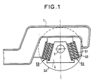
- Figure 1 schematically shows a bogie chassis 1 and an axle box 4 connected to the chassis by a primary suspension formed by two blocks 5A, and 5B, formed of an elastomer such as rubber 50 reinforced by means of metal reinforcements 51.
- FIG. 2 In FIG. 2 are shown only a chassis 1 and a single axle 2 provided with its two wheels 3.
- the axle 2 can therefore be oriented by turning around a vertical axis 2 of a value + a or - a by relative to a rest position corresponding to an axis Y perpendicular to the longitudinal axis X of the chassis.
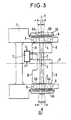
- Figure 3 are shown the frame 1, the axle 2 and its two wheels 3, but also two axle boxes 4 in which the axle rotates, four elastic blocks 5A, 5B, carrying the two boxes.
- the blocks 5A, 5B constituting the primary suspension of the axle are each provided with a cavity 6, and with a distribution system 7 ensuring the supply of fluid to the cavities 6 by lines 8 and 9.
- the two pipes 8 supply the cavities 6 of the two blocks 5B and the two pipes 9 supply the cavities 6 of the two blocks 5A.
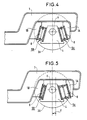
- Figure 4 shows in partially cut elevation, an axle box 4, two elastic elements 5A, 5B and their cavity 6, the element 5A being connected to a frame element 1A and the element 5B being connected to a chassis 1B.
- the orienta tion of the axle is zero.
- Figure 5 is a view similar to that of Figure 4, but in which the axle is inclined at an angle + a (see Figure 3) which corresponds to a displacement d of the axle box.
- the axle is tilted as follows:
- the railway comprises, at the entrance of a curve, a transmitter which sends a signal giving the radius of curvature.
- the vehicle includes a sensor which records this signal and processing means which transforms it into information i.
- the distribution system 7 is connected to a hydraulic source delivering a fluid under pressure P and it is controlled by the information i to supply either the pipes 8 or the pipes 9.
- the cavities 6 of the blocks 5A are then under pressure and they deform the blocks 5A in extension, while the blocks 5B are compressed (see FIG. 5).
- the axle then tilts at an angle a varying between 0 and + a which represents a maximum inclination, and this as a function of the pressure delivered by the distribution system 7, this pressure being a function of the radius of curvature of the track . It is therefore possible to modulate the orientation angle of the axle as a function of the radius of curvature of the track.
- the signal can come from external signals other than the radius of curvature of the railway.
- the invention makes it possible to produce an easily and securely orientable axle, remaining reliable over time, without significantly encumbering the usual environment of the axle.
Landscapes
- Engineering & Computer Science (AREA)
- Mechanical Engineering (AREA)
- Vehicle Body Suspensions (AREA)
- Transition And Organic Metals Composition Catalysts For Addition Polymerization (AREA)
- Supporting Of Heads In Record-Carrier Devices (AREA)
- Springs (AREA)
Abstract
Description
- La présente invention est relative à un essieu de véhicule ferroviaire, cet essieu étant monté entre deux boîtes d'essieu reliées à un châssis de caisse ou de bogie au moyen d'une suspension primaire.
- Cette suspension primaire est souvent réalisée par deux blocs en élastomère à armatures métalliques, disposés de part et d'autre de la boîte d'essieu et prenant appui sur le châssis.
- Dans certaines conditions d'exploitation, et notamment en courbe, il est utile que les essieux soient orientables, afin qu'ils s'inscrivent correctement dans la courbe évitant ainsi une usure trop importante des roues.
- On connait, notamment par le document FR-A-2 530 267, des dispositifs d'orientation entièrement mécaniques permettant d'orienter les essieux. Ces dispositifs comportent des palonniers et des bielles actionnant directement les boîtes d'essieu.
- L'orientation des essieux est donc possible, en raison de la flexibilité de la suspension primaire.
- Mais ces dispositifs sont complexes et de fiabilité incertaine. Par ailleurs, ces dispositifs sont encombrants et difficiles à loger à l'intérieur d'un bogie déjà bien encombré.
- Un but de l'invention est de réaliser un essieu possédant une suspension primaire et muni de moyens d'orientation fiables, simples et peu emcombrants.
- L'invention a pour objet un essieu de véhicule ferroviaire à suspension primaire et orientation variable, tournant entre deux boîtes d'essieu et monté sur un châssis, comportant une suspension primaire comprenant, pour chacune des boîtes d'essieu, deux blocs élastiques disposés de part et d'autre de la boîte d'essieu, caractérisé en ce que lesdits blocs possèdent une cavité intérieure reliée, par un système de distribution, à une source de fluide à pression réglable.
- Il est décrit ci-après, exemple d'essieu selon l'invention, en référence au dessin annexé dans lequel :
- - la figure 1 est une vue partielle schématique d'un essieu selon l'invention,
- - la figure 2 est un schéma de principe qui montre l'orientation possible d'un essieu par rapport à un châssis quelconque,
- - la figure 3 est une vue de dessus d'un essieu selon l'invention,
- - la figure 4 est une vue selon la ligne IV-IV de la figure 3, l'essieu étant en position d'orientation nulle,
- - la figure 5 est une vue analogue, l'essieu étant orienté d'un angle + a.
- La figure 1 montre schématiquement un châssis de bogie 1 et une boîte d'essieu 4 reliée au châssis par une suspension primaire formée de deux blocs 5A, et 5B, formés d'un élastomère tel que le caoutchouc 50 armé au moyen d'armatures métalliques 51.
- Dans la figure 2 sont représentés uniquement un châssis 1 et un seul essieu 2 muni de ses deux roues 3. L'essieu 2 peut donc s'orienter en tournant autour d'un axe vertical 2 d'une valeur + a ou - a par rapport à une position de repos correspondant à un axe Y perpendiculaire à l'axe longitudinal X du châssis.
- Bien entendu, en courbe, l'autre essieu d'un bogie ou d'un véhicule doit être orienté d'une valeur - a quand l'essieu 2 est orienté d'une valeur + a, et inversement.
- Dans la figure 3 sont représentés le châssis 1, l'essieu 2 et ses deux roues 3, mais aussi deux boîtes d'essieu 4 dans lesquelles tourne l'essieu, quatre blocs élastiques 5A, 5B, portant les deux boîtes. Selon la caractéristique principale de l'invention, les blocs 5A, 5B constituant la suspension primaire de l'essieu sont munis chacun d'une cavité 6, et d'un système de distribution 7 assurant l'alimentation en fluide des cavités 6 par des canalisations 8 et 9.
- Les deux canalisations 8 assurent l'alimentation des cavités 6 des deux blocs 5B et les deux canalisations 9 assurent l'alimentation des cavités 6 des deux blocs 5A.
- La figure 4 montre en élévation partiellement coupée, une boîte d'essieu 4, deux éléments élastiques 5A, 5B et leur cavité 6, l'élément 5A étant relié à un élément de châssis 1A et l'élément 5B étant relié à un élément de châssis 1B. Dans cette figure, l'orienta tion de l'essieu est nulle.
- La figure 5 est une vue analogue à celle de la figure 4, mais dans laquelle l'essieu est incliné d'un angle + a (voir figure 3) ce qui correspond à un déplacement d de la boîte d'essieu.
- Une inclinaison de l'essieu s'effectue de la manière suivante :
- La voie ferrée comporte, à l'entrée d'une courbe, un émetteur qui envoie un signal donnant le rayon de courbure. Le véhicule comporte un capteur qui enregistre ce signal et des moyens de traitement qui le transforme en une information i.
- Le système de distribution 7 est connecté à une source hydraulique délivrant un fluide sous pression P et il est commandé par l'information i pour alimenter soit les canalisations 8, soit les canalisations 9.
- Si les canalisations 8 soit alimentées, les cavités 6 des blocs 5A sont alors sous pression et elles déforment les blocs 5A en extension, tandis que les blocs 5B sont comprimés (voir figure 5).
- L'essieu s'incline alors d'un angle a variant entre 0 et + a qui représente une inclinaison maximale, et ceci en fonction de la pression délivrée par le système de distribution 7, cette pression étant fonction du rayon de courbure de la voie. On peut donc moduler l'angle d'orientation de l'essieu en fonction du rayon de courbure de la voie.
- Bien entendu le signal peut provenir de signaux extérieurs autres que le rayon de courbure de la voie ferrée.
- L'invention permet de réaliser un essieu orientable facilement et de manière sûre, restant fiable dans le temps, sans encombrer de manière notable l'environnement habituel de l'essieu.
Claims (2)
Applications Claiming Priority (2)
| Application Number | Priority Date | Filing Date | Title |
|---|---|---|---|
| FR8904680 | 1989-04-10 | ||
| FR8904680A FR2645483B1 (fr) | 1989-04-10 | 1989-04-10 | Dispositif d'orientation d'un essieu d'un vehicule ferroviaire |
Publications (3)
| Publication Number | Publication Date |
|---|---|
| EP0392414A2 true EP0392414A2 (fr) | 1990-10-17 |
| EP0392414A3 EP0392414A3 (en) | 1990-12-05 |
| EP0392414B1 EP0392414B1 (fr) | 1994-03-02 |
Family
ID=9380538
Family Applications (1)
| Application Number | Title | Priority Date | Filing Date |
|---|---|---|---|
| EP90106743A Expired - Lifetime EP0392414B1 (fr) | 1989-04-10 | 1990-04-09 | Essieu à suspension primaire et à orientation variable |
Country Status (8)
| Country | Link |
|---|---|
| EP (1) | EP0392414B1 (fr) |
| JP (1) | JPH072463B2 (fr) |
| AT (1) | ATE102135T1 (fr) |
| CA (1) | CA2014168C (fr) |
| DE (1) | DE69006886T2 (fr) |
| DK (1) | DK0392414T3 (fr) |
| ES (1) | ES2050865T3 (fr) |
| FR (1) | FR2645483B1 (fr) |
Cited By (5)
| Publication number | Priority date | Publication date | Assignee | Title |
|---|---|---|---|---|
| US5199359A (en) * | 1992-05-20 | 1993-04-06 | Innotermodal Inc. | Steerable rail-bogie |
| WO2016131688A1 (fr) * | 2015-02-17 | 2016-08-25 | Siemens Ag Österreich | Ressort primaire pour véhicule ferroviaire |
| EP3241716A1 (fr) * | 2016-04-28 | 2017-11-08 | Siemens AG Österreich | Bogie de véhicule ferroviaire |
| WO2018095961A1 (fr) * | 2016-11-24 | 2018-05-31 | Siemens Ag Österreich | Système de commande de roues pour bogie |
| GB2579344A (en) * | 2018-11-05 | 2020-06-24 | Bombardier Transp Gmbh | Wheel axle guiding assembly with load-dependent pressurising means |
Families Citing this family (3)
| Publication number | Priority date | Publication date | Assignee | Title |
|---|---|---|---|---|
| JP2008247173A (ja) * | 2007-03-30 | 2008-10-16 | Railway Technical Res Inst | 軸箱支持装置 |
| DE102013224933B4 (de) | 2013-12-04 | 2022-05-19 | DB Systemtechnik GmbH | Vorrichtung zur Führung eines Radsatzes im Fahrwerk eines Schienenfahrzeuges |
| FR3034391B1 (fr) * | 2015-04-01 | 2017-03-17 | Sncf Mobilites | Systeme de detection de l'entree en courbe d'une structure de caisse de vehicule ferroviaire |
Family Cites Families (5)
| Publication number | Priority date | Publication date | Assignee | Title |
|---|---|---|---|---|
| FR1273155A (fr) * | 1959-11-11 | 1961-10-06 | Maschf Augsburg Nuernberg Ag | Dispositif pour inscrire dans les courbes les bogies à un ou plusieurs essieux des véhicules ferroviaires |
| DE3123858A1 (de) * | 1981-06-16 | 1982-12-30 | Fried. Krupp Gmbh, 4300 Essen | Laufwerk fuer ein schienenfahrzeug |
| FR2530567A1 (fr) * | 1982-07-26 | 1984-01-27 | Anf Ind | Bogie a essieux orientables pour vehicules ferroviaires |
| JPS59201113A (ja) * | 1983-04-28 | 1984-11-14 | Hitachi Ltd | 車両の操舵制御装置 |
| DE3427952A1 (de) * | 1984-07-28 | 1986-01-30 | Gebr. Happich Gmbh, 5600 Wuppertal | Sonnenblende fuer fahrzeuge |
-
1989
- 1989-04-10 FR FR8904680A patent/FR2645483B1/fr not_active Expired - Fee Related
-
1990
- 1990-04-09 DK DK90106743.9T patent/DK0392414T3/da active
- 1990-04-09 EP EP90106743A patent/EP0392414B1/fr not_active Expired - Lifetime
- 1990-04-09 CA CA002014168A patent/CA2014168C/fr not_active Expired - Fee Related
- 1990-04-09 ES ES90106743T patent/ES2050865T3/es not_active Expired - Lifetime
- 1990-04-09 AT AT90106743T patent/ATE102135T1/de not_active IP Right Cessation
- 1990-04-09 DE DE69006886T patent/DE69006886T2/de not_active Expired - Fee Related
- 1990-04-10 JP JP2094914A patent/JPH072463B2/ja not_active Expired - Fee Related
Cited By (7)
| Publication number | Priority date | Publication date | Assignee | Title |
|---|---|---|---|---|
| US5199359A (en) * | 1992-05-20 | 1993-04-06 | Innotermodal Inc. | Steerable rail-bogie |
| WO2016131688A1 (fr) * | 2015-02-17 | 2016-08-25 | Siemens Ag Österreich | Ressort primaire pour véhicule ferroviaire |
| EP3241716A1 (fr) * | 2016-04-28 | 2017-11-08 | Siemens AG Österreich | Bogie de véhicule ferroviaire |
| AT518699A1 (de) * | 2016-04-28 | 2017-12-15 | Siemens Ag Oesterreich | Fahrwerk für ein Schienenfahrzeug |
| WO2018095961A1 (fr) * | 2016-11-24 | 2018-05-31 | Siemens Ag Österreich | Système de commande de roues pour bogie |
| GB2579344A (en) * | 2018-11-05 | 2020-06-24 | Bombardier Transp Gmbh | Wheel axle guiding assembly with load-dependent pressurising means |
| GB2579344B (en) * | 2018-11-05 | 2021-04-07 | Bombardier Transp Gmbh | Rail vehicle wheel axle guiding assembly with load-dependent pressurising means |
Also Published As
| Publication number | Publication date |
|---|---|
| JPH02293252A (ja) | 1990-12-04 |
| DE69006886T2 (de) | 1994-06-09 |
| FR2645483A1 (fr) | 1990-10-12 |
| ATE102135T1 (de) | 1994-03-15 |
| JPH072463B2 (ja) | 1995-01-18 |
| DE69006886D1 (de) | 1994-04-07 |
| CA2014168C (fr) | 1994-07-19 |
| ES2050865T3 (es) | 1994-06-01 |
| EP0392414B1 (fr) | 1994-03-02 |
| CA2014168A1 (fr) | 1990-10-10 |
| DK0392414T3 (da) | 1994-05-24 |
| EP0392414A3 (en) | 1990-12-05 |
| FR2645483B1 (fr) | 1993-04-30 |
Similar Documents
| Publication | Publication Date | Title |
|---|---|---|
| EP0392414B1 (fr) | Essieu à suspension primaire et à orientation variable | |
| CA2611970C (fr) | Dispositif de direction a encombrement reduit pour atterrisseur d'aeronef | |
| EP0210879A1 (fr) | Dispositif de suspension pour un bras support de roue de véhicule et système de couplage avant-arrière pour une telle suspension | |
| FR2705620A1 (fr) | Véhicule formé d'une suite de modules reliés entre eux par une liaison composite articulée. | |
| EP0072328B1 (fr) | Bogie à essieux orientables | |
| EP0692421A1 (fr) | Procédé de réglage de l'orientation des dispositifs de roulement à roues orientables d'un ensemble roulant sur rail et ensemble roulant utilisant ce procédé | |
| MA31659B1 (fr) | Roue pour vehicule ferroviaire de transport de marchandises ayant une capacite de freinage elevee. | |
| FR2700501A1 (fr) | Véhicule de franchissement d'obstacles. | |
| FR2715624A1 (fr) | Liaison de commande directionnelle d'un train routier directeur arrière. | |
| EP3222485A1 (fr) | Bogie de vehicule ferroviaire comprenant un dispositif de suspension primaire decale | |
| EP3571466B1 (fr) | Procédé et dispositif autonomes de détermination d'une assiette d'un véhicule automobile | |
| EP3222486B1 (fr) | Bogie de véhicule ferroviaire comprenant un châssis abaissé | |
| EP0358563A1 (fr) | Machine à recolter les baies et notamment à vendanger | |
| BE1001489A5 (fr) | Dispositif de reglage de rapprochement d'une remorque par rapport au vehicule tracteur. | |
| FR2474967A1 (fr) | Dispositif de suspension independante pour roues de vehicule | |
| FR2862022A1 (fr) | Dispositif d'ecartement des deux roues d'un meme essieu | |
| EP0394898B1 (fr) | Bogie à deux essieux orientables, monté pivotant sous une caisse d'un véhicule ferroviaire | |
| FR2617788A1 (fr) | Dispositif de commande d'un essieu directeur de vehicule tracte | |
| EP3395640B1 (fr) | Bogie de véhicule ferroviaire comportant un système de freinage comprenant trois disques de frein agencés entre les boîtes d'essieu | |
| EP1712442B1 (fr) | Dispositif de suspension d'un moteur sur un chassis de bogie | |
| FR2739595A1 (fr) | Systeme de suspension, notamment pour vehicule automobile | |
| FR2587961A2 (fr) | Bloc de direction de vehicule automobile comportant un coussin central fixe | |
| EP3309039B1 (fr) | Dispositif de commande pour un véhicule ferroviaire et véhicule ferroviaire comportant ce dispositif de commande | |
| BE1009082A6 (fr) | Guidage d'un vehicule ferroviaire. | |
| WO1993002761A1 (fr) | Vehicule jouet a roues directrices |
Legal Events
| Date | Code | Title | Description |
|---|---|---|---|
| PUAI | Public reference made under article 153(3) epc to a published international application that has entered the european phase |
Free format text: ORIGINAL CODE: 0009012 |
|
| AK | Designated contracting states |
Kind code of ref document: A2 Designated state(s): AT BE CH DE DK ES FR GB GR IT LI LU NL SE |
|
| PUAL | Search report despatched |
Free format text: ORIGINAL CODE: 0009013 |
|
| AK | Designated contracting states |
Kind code of ref document: A3 Designated state(s): AT BE CH DE DK ES FR GB GR IT LI LU NL SE |
|
| 17P | Request for examination filed |
Effective date: 19910603 |
|
| 17Q | First examination report despatched |
Effective date: 19920803 |
|
| GRAA | (expected) grant |
Free format text: ORIGINAL CODE: 0009210 |
|
| AK | Designated contracting states |
Kind code of ref document: B1 Designated state(s): AT BE CH DE DK ES FR GB GR IT LI LU NL SE |
|
| REF | Corresponds to: |
Ref document number: 102135 Country of ref document: AT Date of ref document: 19940315 Kind code of ref document: T |
|
| GBT | Gb: translation of ep patent filed (gb section 77(6)(a)/1977) |
Effective date: 19940225 |
|
| REF | Corresponds to: |
Ref document number: 69006886 Country of ref document: DE Date of ref document: 19940407 |
|
| EPTA | Lu: last paid annual fee | ||
| ITF | It: translation for a ep patent filed | ||
| REG | Reference to a national code |
Ref country code: DK Ref legal event code: T3 |
|
| REG | Reference to a national code |
Ref country code: ES Ref legal event code: FG2A Ref document number: 2050865 Country of ref document: ES Kind code of ref document: T3 |
|
| REG | Reference to a national code |
Ref country code: GR Ref legal event code: FG4A Free format text: 3011592 |
|
| PLBE | No opposition filed within time limit |
Free format text: ORIGINAL CODE: 0009261 |
|
| STAA | Information on the status of an ep patent application or granted ep patent |
Free format text: STATUS: NO OPPOSITION FILED WITHIN TIME LIMIT |
|
| EAL | Se: european patent in force in sweden |
Ref document number: 90106743.9 |
|
| 26N | No opposition filed | ||
| REG | Reference to a national code |
Ref country code: GB Ref legal event code: IF02 |
|
| PGFP | Annual fee paid to national office [announced via postgrant information from national office to epo] |
Ref country code: SE Payment date: 20070412 Year of fee payment: 18 Ref country code: DK Payment date: 20070412 Year of fee payment: 18 Ref country code: LU Payment date: 20070412 Year of fee payment: 18 |
|
| PGFP | Annual fee paid to national office [announced via postgrant information from national office to epo] |
Ref country code: AT Payment date: 20070413 Year of fee payment: 18 Ref country code: CH Payment date: 20070413 Year of fee payment: 18 Ref country code: NL Payment date: 20070413 Year of fee payment: 18 |
|
| PGFP | Annual fee paid to national office [announced via postgrant information from national office to epo] |
Ref country code: DE Payment date: 20070423 Year of fee payment: 18 |
|
| PGFP | Annual fee paid to national office [announced via postgrant information from national office to epo] |
Ref country code: ES Payment date: 20070427 Year of fee payment: 18 |
|
| PGFP | Annual fee paid to national office [announced via postgrant information from national office to epo] |
Ref country code: BE Payment date: 20070502 Year of fee payment: 18 |
|
| PGFP | Annual fee paid to national office [announced via postgrant information from national office to epo] |
Ref country code: GB Payment date: 20070426 Year of fee payment: 18 |
|
| PGFP | Annual fee paid to national office [announced via postgrant information from national office to epo] |
Ref country code: IT Payment date: 20070626 Year of fee payment: 18 |
|
| PGFP | Annual fee paid to national office [announced via postgrant information from national office to epo] |
Ref country code: FR Payment date: 20070416 Year of fee payment: 18 |
|
| PGFP | Annual fee paid to national office [announced via postgrant information from national office to epo] |
Ref country code: GR Payment date: 20070420 Year of fee payment: 18 |
|
| BERE | Be: lapsed |
Owner name: S.A. *GEC ALSTHOM Effective date: 20080430 |
|
| REG | Reference to a national code |
Ref country code: CH Ref legal event code: PL |
|
| REG | Reference to a national code |
Ref country code: DK Ref legal event code: EBP |
|
| EUG | Se: european patent has lapsed | ||
| GBPC | Gb: european patent ceased through non-payment of renewal fee |
Effective date: 20080409 |
|
| NLV4 | Nl: lapsed or anulled due to non-payment of the annual fee |
Effective date: 20081101 |
|
| PG25 | Lapsed in a contracting state [announced via postgrant information from national office to epo] |
Ref country code: DE Free format text: LAPSE BECAUSE OF NON-PAYMENT OF DUE FEES Effective date: 20081101 Ref country code: CH Free format text: LAPSE BECAUSE OF NON-PAYMENT OF DUE FEES Effective date: 20080430 Ref country code: LI Free format text: LAPSE BECAUSE OF NON-PAYMENT OF DUE FEES Effective date: 20080430 Ref country code: NL Free format text: LAPSE BECAUSE OF NON-PAYMENT OF DUE FEES Effective date: 20081101 |
|
| REG | Reference to a national code |
Ref country code: FR Ref legal event code: ST Effective date: 20081231 |
|
| PG25 | Lapsed in a contracting state [announced via postgrant information from national office to epo] |
Ref country code: AT Free format text: LAPSE BECAUSE OF NON-PAYMENT OF DUE FEES Effective date: 20080409 |
|
| PG25 | Lapsed in a contracting state [announced via postgrant information from national office to epo] |
Ref country code: BE Free format text: LAPSE BECAUSE OF NON-PAYMENT OF DUE FEES Effective date: 20080430 |
|
| PG25 | Lapsed in a contracting state [announced via postgrant information from national office to epo] |
Ref country code: FR Free format text: LAPSE BECAUSE OF NON-PAYMENT OF DUE FEES Effective date: 20080430 Ref country code: DK Free format text: LAPSE BECAUSE OF NON-PAYMENT OF DUE FEES Effective date: 20080430 |
|
| REG | Reference to a national code |
Ref country code: ES Ref legal event code: FD2A Effective date: 20080410 |
|
| PG25 | Lapsed in a contracting state [announced via postgrant information from national office to epo] |
Ref country code: GB Free format text: LAPSE BECAUSE OF NON-PAYMENT OF DUE FEES Effective date: 20080409 Ref country code: GR Free format text: LAPSE BECAUSE OF NON-PAYMENT OF DUE FEES Effective date: 20081104 |
|
| PG25 | Lapsed in a contracting state [announced via postgrant information from national office to epo] |
Ref country code: ES Free format text: LAPSE BECAUSE OF NON-PAYMENT OF DUE FEES Effective date: 20080410 |
|
| PG25 | Lapsed in a contracting state [announced via postgrant information from national office to epo] |
Ref country code: IT Free format text: LAPSE BECAUSE OF NON-PAYMENT OF DUE FEES Effective date: 20080409 |
|
| PG25 | Lapsed in a contracting state [announced via postgrant information from national office to epo] |
Ref country code: LU Free format text: LAPSE BECAUSE OF NON-PAYMENT OF DUE FEES Effective date: 20080409 |
|
| PG25 | Lapsed in a contracting state [announced via postgrant information from national office to epo] |
Ref country code: SE Free format text: LAPSE BECAUSE OF NON-PAYMENT OF DUE FEES Effective date: 20080410 |