EP3241716A1 - Bogie de véhicule ferroviaire - Google Patents
Bogie de véhicule ferroviaire Download PDFInfo
- Publication number
- EP3241716A1 EP3241716A1 EP17164979.1A EP17164979A EP3241716A1 EP 3241716 A1 EP3241716 A1 EP 3241716A1 EP 17164979 A EP17164979 A EP 17164979A EP 3241716 A1 EP3241716 A1 EP 3241716A1
- Authority
- EP
- European Patent Office
- Prior art keywords
- chassis
- actuator unit
- actuator
- swing arm
- wheel
- Prior art date
- Legal status (The legal status is an assumption and is not a legal conclusion. Google has not performed a legal analysis and makes no representation as to the accuracy of the status listed.)
- Granted
Links
Images

Classifications
-
- B—PERFORMING OPERATIONS; TRANSPORTING
- B61—RAILWAYS
- B61F—RAIL VEHICLE SUSPENSIONS, e.g. UNDERFRAMES, BOGIES OR ARRANGEMENTS OF WHEEL AXLES; RAIL VEHICLES FOR USE ON TRACKS OF DIFFERENT WIDTH; PREVENTING DERAILING OF RAIL VEHICLES; WHEEL GUARDS, OBSTRUCTION REMOVERS OR THE LIKE FOR RAIL VEHICLES
- B61F5/00—Constructional details of bogies; Connections between bogies and vehicle underframes; Arrangements or devices for adjusting or allowing self-adjustment of wheel axles or bogies when rounding curves
- B61F5/38—Arrangements or devices for adjusting or allowing self- adjustment of wheel axles or bogies when rounding curves, e.g. sliding axles, swinging axles
- B61F5/386—Arrangements or devices for adjusting or allowing self- adjustment of wheel axles or bogies when rounding curves, e.g. sliding axles, swinging axles fluid actuated
Definitions
- the invention relates to a chassis for a rail vehicle, comprising at least one landing gear frame, at least one pair of wheels or at least one wheelset and with an active wheel control or Radsatz facedung having at least one actuator and at least one designed as a hydraulic jack elastic bearing.
- Landing gears for rail vehicles must have a high driving safety. This can be improved, for example, by the arrangement of an active wheel control or wheel set control.
- the targeted placement of wheels or wheelsets by actively rotating the same about their vertical axes is used in a known manner to prevent unstable driving conditions.
- the ride comfort is increased by avoiding disturbing vibrations in a rail vehicle.
- the active wheel control or Radsatz tortureung causes a reduction in the wear of wheels and rails.
- An installation of an active wheel control or wheelset control brings with it the requirement to have to arrange additional components (eg actuators) in the chassis. This often leads to conflicts with limited space budgets. Furthermore, these additional components must be protected from environmental influences.
- the prior art describes, for example, the DE 10 2009 041 110 A1 fluidic actuators and their arrangement in a chassis for rail vehicles.
- the interaction of two actuators is shown, which among other things adjust the steering angle of wheelsets about their vertical axes.
- a first actuator impresses a first wheel set quasi-static, a second actuator a second wheel set dynamic steering angle deflections.
- the actuators are connected via handlebars with the wheelsets.
- Said approach has in its known form the disadvantage that the actuators are exposed to the surroundings of the chassis and exposed to the influence of environmental conditions such as weather, rockfall, vandalism, etc. are exposed.
- the EP 0 870 664 B1 shows a method and a device for wheelset management of rail vehicles.
- a device is shown in which the setting angle of wheelsets is generated by a two-chamber fluid bushing.
- a swing arm connects the wheel set with a chassis frame.
- the fluid sleeve is disposed between the swing arm and the chassis frame. Their chambers are mutually acted upon by fluid via corresponding connections, whereby a relative movement between the swing arm and the chassis frame is generated.
- an embodiment is shown with a double spring leaf-Radsatzscher for the change of Radsatz adjustment angles.
- the mentioned approach has in its known form the disadvantage that the embodiments shown exposed to the environment of the chassis and the influence of environmental conditions such as weather, rockfall, vandalism, etc. are exposed or that provided their own components for the encapsulation of the facilities Need to become. Furthermore, the devices shown are less suitable for the generation of larger wheelset adjustment angle, as they are to be set, for example, for a bow travel of the rail vehicle, but rather for the generation of small wheelset adjustment angle for the compensation of dynamic disturbances.
- the invention is therefore based on the object to provide a comparison with the prior art improved chassis.
- this object is achieved with a chassis of the type mentioned, in which the at least one actuator unit is disposed within a swing arm, within a wheel bearing housing or within the chassis frame.
- a swing arm without actuator unit can be replaced by a swing arm, within which an actuator unit is arranged.
- the arrangement of the actuator within a component of the chassis continues to provide a favorable sheathing of the actuator by this component achieved.
- the actuator unit is well protected against environmental influences such as weather, rockfall, vandalism, etc. Separate means for encapsulating the actuator unit can be dispensed with.
- the at least one actuator unit is designed as a pneumatic actuator.
- the pneumatic actuator can be fed from the compressed air system of the vehicle, as it is used for brake systems, for example.
- the presence of air procurement equipment in rail vehicles is common. Additional units can therefore be dispensed with, whereby a cost advantage is achieved.
- a separation and rebuilding of the pneumatic actuator in maintenance are possible quickly and easily.
- air as the medium of the pneumatic actuator is not flammable, not environmentally hazardous and leads to leaks in no pollution.
- the actuator unit has at least one measuring device for the determination of information about kinetic states of the chassis.
- the measuring device may, for example, be connected via line paths to a control device of a wheel or wheel set controller.
- the actuator unit has a first connection and a second connection, which are separably connected to supply lines via quick-release couplings.
- a mechanical force translator is provided which is at least partially disposed within the swing arm, at least partially within the wheel bearing housing or at least partially within the chassis frame.
- the mechanical force translator By the mechanical force translator a translation of the force generated by the actuator unit and thus a favorable flexibility in the dimensioning of the actuator unit is achieved.
- Standard components can be provided; adaptation to a chassis-specific actuating force level can take place via a corresponding dimensioning and arrangement of the mechanical force translator.
- the mechanical force translator enables the bridging of a local distance between the installation location of the actuator unit, a chassis frame and pairs of wheels or wheelsets. This results in an advantageous flexibility for the arrangement of the actuator unit in the chassis.
- the mechanical power translator is disposed within a component of the landing gear. This results in a first favorable sheathing, which protects the mechanical force translator from environmental influences. On separate means for its encapsulation can be omitted. Secondly, this provides the advantage of a cheap use of a limited space budget.
- FIG. 1 Section of a first, exemplary variant of a chassis according to the invention shown in side view comprises a section of a chassis frame 1 and a pair of wheels 2, which rests on a track 11. Furthermore, a wheel bearing 6, a swing arm 3 in a sectional view and a wheel bearing housing 7 are shown.
- the pair of wheels 2 comprises two wheels, which are connected to each other via a mechanical coupling, not shown.
- the chassis frame 1 is part of a primary sprung plane of the chassis and the pair of wheels 2, the wheel bearing 6, the swing arm 3 and the wheel bearing housing 7 belong to a non-sprung plane of the chassis.
- the swing arm 3 is connected to the wheel bearing housing 7 and supported rotatably together about a wheel axle 8.
- a passive elastic bearing 5 with frequency and amplitude-dependent static and increased dynamic stiffness is provided for generating a dynamic stiffness for guiding the pair of wheels 2, which is connected to the swing arm 3.
- the elastic bearing 5 is designed as a cylindrical, hydraulic bush whose circular base is arranged parallel to a plane spanned by the directions of a chassis longitudinal axis 9 and a landing gear 10 axis.
- the hydraulic bushing has a stabilizing, resilient and damping effect primarily in the plane of its base, ie in the direction of the chassis longitudinal axis 9 and in the direction of the chassis vertical axis 10.
- a vibration-mechanical decoupling the two levels achieved from each other is a vibration-mechanical decoupling the two levels achieved from each other.
- An actuator unit 4 is connected in parallel to the elastic bearing 5 with respect to its mechanical action.
- the actuator unit 4 is designed as a pneumatic actuator or as a double-acting pneumatic cylinder and comprises a cylindrical piston 12 with a piston seal, not shown, and a piston rod 13. These components are guided within the swing arm 3.
- a cylindrical recess is formed, which acts as a housing 14 of the piston 12 and the piston rod 13.
- Via a first port 19 the first air chamber 17 is supplied with compressed air, via a second port 20, the second air chamber 18th
- the piston seal prevents inadvertent pressure equalization between the first air chamber 17 and the second air chamber 18th
- the housing 14 is sealed against its surroundings.
- a pressure compensation can take place exclusively via the first port 19 and the second port 20.
- devices for processing and promotion of compressed air and for a control or regulation of the air pressure eg compressors, lines, valves, control devices, etc.
- the first terminal 19 and the second terminal 20 are separably connected via not shown quick couplings with supply lines, also not shown.
- the recess has a seal and a scraper ring, firstly to prevent inadvertent pressure equalization of the second air chamber 18 with its surroundings, and secondly, ingress of dirt into the second air chamber 18.
- the piston rod 13 has a first stop buffer 30, extends in the direction of the chassis longitudinal axis 9 and contacted via the first stop buffer 30, a second stop buffer 31 which is mounted on a cantilever 24.
- the cantilever 24 is connected to the chassis frame 1.
- the contours of the first stop buffer 30 and the second stop buffer 31 are circular arc-shaped, to allow a rolling of the piston rod 13 on the cantilever 24 and thus a compensation of relative movements between the non-sprung and the primary sprung plane of the chassis.
- an actuator force 22 is formed which, owing to the arrangement of the actuator unit 4 with respect to its position, in the direction of the chassis longitudinal axis 9 runs. Both the extension and the retraction movement of the piston 12 are controlled by means of compressed air and the actuator force 22 formed.
- the actuator unit 4 and has a measuring device, not shown, for the determination of information about kinetic states of the chassis. This is connected via lines not shown with a control device also not shown a wheel or wheelset.
- Fig. 2 shows a side view of a second, exemplary embodiment of a chassis according to the invention, wherein a section of a chassis frame 1, a pair of wheels 2 on a track 11, a wheel bearing 6 and a wheel bearing housing 7 are shown. Furthermore, a swing arm 3 is shown in sectional view, which is connected to the wheel bearing housing 7 and is rotatably mounted together with this about a wheel axle 8.
- the pair of wheels 2 comprises two wheels, which are connected to each other via a mechanical coupling, not shown.
- a passive elastic bearing 5 with frequency and amplitude-dependent static and increased dynamic stiffness is provided for generating a dynamic stiffness for guiding the pair of wheels 2, which is designed as a hydraulic jack and connected to the swing arm 3.
- an actuator unit 4 is arranged within the swing arm 3. It is designed as a pneumatic actuator or as a double-acting pneumatic cylinder.
- the actuator unit 4 has a piston 12 with a first piston surface 15 and a second piston surface 16 and a piston rod 13.
- a formed cylindrical recess which acts as a housing 14 of the actuator 4.
- the housing 14 forms, together with the first piston surface 15, a first air chamber 17 and, together with the second piston surface 16, a second air chamber 18.
- the first air chamber 17 is sealed against the second air chamber 18 to prevent inadvertent pressure equalization between these two chambers.
- a first terminal 19 is provided, on a second end face 26 of the housing 14, a second port 20.
- the first air chamber 17 is supplied with compressed air, via the second port 20, the second air chamber 18th
- devices for processing and promotion of compressed air and for a control or regulation of the air pressure eg compressors, lines, valves, control devices, etc.
- the first terminal 19 and the second terminal 20 are separably connected via not shown quick couplings with supply lines, also not shown.
- the actuator unit 4 is sealed against the swing arm 3 in order to avoid unintentional pressure compensation operations.
- a wedge 27 is connected, which, disposed within the swing arm 3, a roller 28 touches, which is rotatably mounted on a cantilever 24.
- the cantilever 24 is connected to the chassis frame 1.
- the wedge 27 and the roller 28 are components of a mechanical force translator 29.
- power translators 29 with cams, link guides, etc. are also conceivable.
- the inner contour of the swing arm 3 is designed accordingly.
- the swing arm 3 is sealed from the environment to prevent ingress of dirt.
- an actuator force 22 By acting on the first piston surface 15 with compressed air, an actuator force 22 is formed, which moves the piston 12, the piston rod 13 and the wedge 27 vertically upward and loads the roller 28.
- the Aktuatorkraft 22 is increased and changed in their direction of action on the contact between the wedge 27 and the roller 28 according to the known wedge principle. Consequently acts on the roller 28, and on the cantilever 24 on the chassis frame 1, a horizontal translator force 23rd against the translator force 23 acts a restoring force due to the rigidity of the elastic bearing. 5
- a pressurization of the second piston surface 16 with compressed air leads to a movement of said components vertically downwards and to a relief of the roller 28th
- the restoring force of the elastic bearing 5 causes the contact between the roller 28 and the wedge 27 at any time, so even when the roller 28, remains upright. Due to the translator force 23, a relative movement between the swing arm 3 and the chassis frame 1 is generated and thereby made an adjustment of position and position of the pair of wheels 2. As a result, the setting task of the actuator unit 4 with respect to the pair of wheels 2 is performed.
- the actuator unit 4 and the power booster 29 each have a, not shown measuring device for the determination of information about kinetic states of the chassis. These are connected via lines not shown with a control device also not shown a wheel or wheelset.
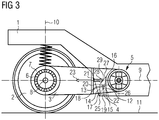
- FIG. 3 shows Fig. 3 an embodiment variant in which an actuator unit 4 is arranged vertically within a chassis frame 1.
- the actuator unit 4 is designed as a double-acting pneumatic cylinder, which has a first air chamber 17 and a second air chamber 18.
- the first air chamber 17 is supplied via a first port 19, the second air chamber 18 via a second port 20 with compressed air.
- the force acting on a piston 12 compressed air generates a vertical actuator force 22, which is transmitted to a piston rod 13 and a wedge 27.
- the piston 12 moves in a cylindrical recess in the chassis frame 1, which acts as a housing 14 of the actuator 4 and is sealed against their environment.
- the actuator force 22 is translated via the wedge 27 and a roller 28 into a horizontal translator force 23.
- the wedge 27 and the roller 28 are components of a mechanical force translator 29.
- the horizontal translator force 23 acts on the swing arm 3 via the roller 28, which is rotatably mounted on a cast rib 21 of the swing arm 3. Due to the effect of the translator force 23 and a relative movement between the swing arm 3 and the chassis frame 1, an adjustment of position and position of a pair of wheels 2 is made. As a result, the setting task of the actuator unit 4 with respect to the pair of wheels 2 is performed.
- FIG. 3 shown principle those embodiments that in Fig. 1 and Fig. 2 are shown.
- Fig. 1, Fig. 2 and Fig. 3 shown use of wheel bearings 6 and wheel bearing housings 7 is exemplary. Arrangements of wheelsets and wheelset bearing housings are also possible according to the invention.
- the adjusting movements of the individual actuator units 4 are coordinated with one another via corresponding control or regulating devices in order to generate tangential positions with respect to a track curve to be traveled, for example for all wheels in the chassis.
Landscapes
- Engineering & Computer Science (AREA)
- Mechanical Engineering (AREA)
- Vehicle Body Suspensions (AREA)
Applications Claiming Priority (1)
| Application Number | Priority Date | Filing Date | Title |
|---|---|---|---|
| ATA50379/2016A AT518699A1 (de) | 2016-04-28 | 2016-04-28 | Fahrwerk für ein Schienenfahrzeug |
Publications (3)
| Publication Number | Publication Date |
|---|---|
| EP3241716A1 true EP3241716A1 (fr) | 2017-11-08 |
| EP3241716B1 EP3241716B1 (fr) | 2019-05-29 |
| EP3241716B8 EP3241716B8 (fr) | 2019-08-07 |
Family
ID=58489607
Family Applications (1)
| Application Number | Title | Priority Date | Filing Date |
|---|---|---|---|
| EP17164979.1A Active EP3241716B8 (fr) | 2016-04-28 | 2017-04-05 | Bogie de véhicule ferroviaire |
Country Status (2)
| Country | Link |
|---|---|
| EP (1) | EP3241716B8 (fr) |
| AT (1) | AT518699A1 (fr) |
Citations (4)
| Publication number | Priority date | Publication date | Assignee | Title |
|---|---|---|---|---|
| US4519329A (en) * | 1982-07-26 | 1985-05-28 | A.N.F. Industrie | Bogie with orientable axles for railroad vehicles |
| EP0392414A2 (fr) * | 1989-04-10 | 1990-10-17 | Gec Alsthom Sa | Essieu à suspension primaire et à orientation variable |
| EP0870664A2 (fr) * | 1997-04-11 | 1998-10-14 | Deutsche Waggonbau AG | Procédé et dispositif pour le guidage des trains des roues des véhicules ferroviaires |
| JP2008247173A (ja) * | 2007-03-30 | 2008-10-16 | Railway Technical Res Inst | 軸箱支持装置 |
Family Cites Families (1)
| Publication number | Priority date | Publication date | Assignee | Title |
|---|---|---|---|---|
| DE4240098A1 (de) * | 1992-11-28 | 1994-06-01 | Krupp Verkehrstechnik Gmbh | Fahrwerk für Schienenfahrzeuge |
-
2016
- 2016-04-28 AT ATA50379/2016A patent/AT518699A1/de not_active Application Discontinuation
-
2017
- 2017-04-05 EP EP17164979.1A patent/EP3241716B8/fr active Active
Patent Citations (4)
| Publication number | Priority date | Publication date | Assignee | Title |
|---|---|---|---|---|
| US4519329A (en) * | 1982-07-26 | 1985-05-28 | A.N.F. Industrie | Bogie with orientable axles for railroad vehicles |
| EP0392414A2 (fr) * | 1989-04-10 | 1990-10-17 | Gec Alsthom Sa | Essieu à suspension primaire et à orientation variable |
| EP0870664A2 (fr) * | 1997-04-11 | 1998-10-14 | Deutsche Waggonbau AG | Procédé et dispositif pour le guidage des trains des roues des véhicules ferroviaires |
| JP2008247173A (ja) * | 2007-03-30 | 2008-10-16 | Railway Technical Res Inst | 軸箱支持装置 |
Also Published As
| Publication number | Publication date |
|---|---|
| EP3241716B1 (fr) | 2019-05-29 |
| AT518699A1 (de) | 2017-12-15 |
| EP3241716B8 (fr) | 2019-08-07 |
Similar Documents
| Publication | Publication Date | Title |
|---|---|---|
| EP3390196B1 (fr) | Train roulant pour un véhicule ferroviaire | |
| EP3046824B1 (fr) | Train de roulement d'un véhicule ferroviaire | |
| WO2014170234A1 (fr) | Châssis pourvu d'ensembles roue couplés transversalement | |
| EP3544875B1 (fr) | Châssis pour véhicules sur rails | |
| EP0870664B1 (fr) | Procédé et dispositif pour le guidage des trains de roues des véhicules ferroviaires | |
| EP4339056A1 (fr) | Véhicule ferroviaire doté d'un châssis et d'un dispositif de compensation de roulis ainsi que dispositif de compensation de roulis, en particulier pour un véhicule ferroviaire | |
| EP2065286A1 (fr) | Véhicule ferroviaire et procédé destiné au couplage des bogies d'un véhicule ferroviaire | |
| EP3239015B1 (fr) | Guidage latéral du boudin à contrôle de force pour un véhicule sur rail | |
| EP3241716B1 (fr) | Bogie de véhicule ferroviaire | |
| EP3470288B1 (fr) | Véhicule ferroviaire pourvu d'entrainement direct compact | |
| EP3529121B1 (fr) | Système de commande de roues pour bogie | |
| WO2008101903A1 (fr) | Véhicule avec un bogie intercaisse et un support antiroulis | |
| EP3978330B1 (fr) | Élément élastique et châssis | |
| EP2158114B1 (fr) | Véhicule sur rails à suspension monoétage | |
| CH616625A5 (en) | Device for guiding a bogie of a rail vehicle on the underframe of a wagon body | |
| EP0930210B1 (fr) | Train de roulement pour véhicules ferroviaires et véhicule ferroviaire avec au moins un tel train de roulement | |
| CH659803A5 (de) | Schlingerdaempfungsanordnung fuer drehgestell-schienenfahrzeuge. | |
| EP2353961A1 (fr) | Bogie pour un véhicule sur rail | |
| AT524550B1 (de) | Fahrwerk für ein Schienenfahrzeug | |
| EP3490869A1 (fr) | Articulation simple à élasticité transversale présentant un guidage rectiligne approximatif au moyen d'un timon | |
| EP3752402B1 (fr) | Train de roulement pour un véhicule ferroviaire | |
| EP0516972B1 (fr) | Dispositif d'amortisseur synchrone | |
| DE102022103096A1 (de) | Schienenfahrzeugfahrwerk mit einer Vorrichtung zum Steuern einer Radachse | |
| DE102016124839B3 (de) | Anordnung zum Dämpfen von mechanischen Schwingungen | |
| DE1771066U (de) | Achslenker in biegesteifer konstruktion fuer farhzeuge, besonders fuer schienenfahrzeuge. |
Legal Events
| Date | Code | Title | Description |
|---|---|---|---|
| PUAI | Public reference made under article 153(3) epc to a published international application that has entered the european phase |
Free format text: ORIGINAL CODE: 0009012 |
|
| STAA | Information on the status of an ep patent application or granted ep patent |
Free format text: STATUS: THE APPLICATION HAS BEEN PUBLISHED |
|
| AK | Designated contracting states |
Kind code of ref document: A1 Designated state(s): AL AT BE BG CH CY CZ DE DK EE ES FI FR GB GR HR HU IE IS IT LI LT LU LV MC MK MT NL NO PL PT RO RS SE SI SK SM TR |
|
| AX | Request for extension of the european patent |
Extension state: BA ME |
|
| STAA | Information on the status of an ep patent application or granted ep patent |
Free format text: STATUS: REQUEST FOR EXAMINATION WAS MADE |
|
| 17P | Request for examination filed |
Effective date: 20180507 |
|
| RBV | Designated contracting states (corrected) |
Designated state(s): AL AT BE BG CH CY CZ DE DK EE ES FI FR GB GR HR HU IE IS IT LI LT LU LV MC MK MT NL NO PL PT RO RS SE SI SK SM TR |
|
| RIC1 | Information provided on ipc code assigned before grant |
Ipc: B61F 5/38 20060101AFI20181012BHEP |
|
| GRAP | Despatch of communication of intention to grant a patent |
Free format text: ORIGINAL CODE: EPIDOSNIGR1 |
|
| STAA | Information on the status of an ep patent application or granted ep patent |
Free format text: STATUS: GRANT OF PATENT IS INTENDED |
|
| INTG | Intention to grant announced |
Effective date: 20181127 |
|
| GRAS | Grant fee paid |
Free format text: ORIGINAL CODE: EPIDOSNIGR3 |
|
| GRAA | (expected) grant |
Free format text: ORIGINAL CODE: 0009210 |
|
| STAA | Information on the status of an ep patent application or granted ep patent |
Free format text: STATUS: THE PATENT HAS BEEN GRANTED |
|
| AK | Designated contracting states |
Kind code of ref document: B1 Designated state(s): AL AT BE BG CH CY CZ DE DK EE ES FI FR GB GR HR HU IE IS IT LI LT LU LV MC MK MT NL NO PL PT RO RS SE SI SK SM TR |
|
| REG | Reference to a national code |
Ref country code: GB Ref legal event code: FG4D Free format text: NOT ENGLISH |
|
| REG | Reference to a national code |
Ref country code: CH Ref legal event code: EP |
|
| REG | Reference to a national code |
Ref country code: AT Ref legal event code: REF Ref document number: 1138082 Country of ref document: AT Kind code of ref document: T Effective date: 20190615 |
|
| REG | Reference to a national code |
Ref country code: DE Ref legal event code: R096 Ref document number: 502017001422 Country of ref document: DE |
|
| REG | Reference to a national code |
Ref country code: IE Ref legal event code: FG4D Free format text: LANGUAGE OF EP DOCUMENT: GERMAN |
|
| REG | Reference to a national code |
Ref country code: CH Ref legal event code: NV Representative=s name: SIEMENS SCHWEIZ AG, CH Ref country code: CH Ref legal event code: PK Free format text: BERICHTIGUNG B8 |
|
| RAP2 | Party data changed (patent owner data changed or rights of a patent transferred) |
Owner name: SIEMENS MOBILITY GMBH |
|
| REG | Reference to a national code |
Ref country code: DE Ref legal event code: R081 Ref document number: 502017001422 Country of ref document: DE Owner name: SIEMENS MOBILITY GMBH, AT Free format text: FORMER OWNER: SIEMENS AG OESTERREICH, WIEN, AT Ref country code: DE Ref legal event code: R081 Ref document number: 502017001422 Country of ref document: DE Owner name: SIEMENS MOBILITY AUSTRIA GMBH, AT Free format text: FORMER OWNER: SIEMENS AG OESTERREICH, WIEN, AT |
|
| REG | Reference to a national code |
Ref country code: NL Ref legal event code: MP Effective date: 20190529 |
|
| REG | Reference to a national code |
Ref country code: LT Ref legal event code: MG4D |
|
| PG25 | Lapsed in a contracting state [announced via postgrant information from national office to epo] |
Ref country code: FI Free format text: LAPSE BECAUSE OF FAILURE TO SUBMIT A TRANSLATION OF THE DESCRIPTION OR TO PAY THE FEE WITHIN THE PRESCRIBED TIME-LIMIT Effective date: 20190529 Ref country code: NO Free format text: LAPSE BECAUSE OF FAILURE TO SUBMIT A TRANSLATION OF THE DESCRIPTION OR TO PAY THE FEE WITHIN THE PRESCRIBED TIME-LIMIT Effective date: 20190829 Ref country code: SE Free format text: LAPSE BECAUSE OF FAILURE TO SUBMIT A TRANSLATION OF THE DESCRIPTION OR TO PAY THE FEE WITHIN THE PRESCRIBED TIME-LIMIT Effective date: 20190529 Ref country code: AL Free format text: LAPSE BECAUSE OF FAILURE TO SUBMIT A TRANSLATION OF THE DESCRIPTION OR TO PAY THE FEE WITHIN THE PRESCRIBED TIME-LIMIT Effective date: 20190529 Ref country code: HR Free format text: LAPSE BECAUSE OF FAILURE TO SUBMIT A TRANSLATION OF THE DESCRIPTION OR TO PAY THE FEE WITHIN THE PRESCRIBED TIME-LIMIT Effective date: 20190529 Ref country code: LT Free format text: LAPSE BECAUSE OF FAILURE TO SUBMIT A TRANSLATION OF THE DESCRIPTION OR TO PAY THE FEE WITHIN THE PRESCRIBED TIME-LIMIT Effective date: 20190529 Ref country code: ES Free format text: LAPSE BECAUSE OF FAILURE TO SUBMIT A TRANSLATION OF THE DESCRIPTION OR TO PAY THE FEE WITHIN THE PRESCRIBED TIME-LIMIT Effective date: 20190529 Ref country code: PT Free format text: LAPSE BECAUSE OF FAILURE TO SUBMIT A TRANSLATION OF THE DESCRIPTION OR TO PAY THE FEE WITHIN THE PRESCRIBED TIME-LIMIT Effective date: 20190930 |
|
| PG25 | Lapsed in a contracting state [announced via postgrant information from national office to epo] |
Ref country code: LV Free format text: LAPSE BECAUSE OF FAILURE TO SUBMIT A TRANSLATION OF THE DESCRIPTION OR TO PAY THE FEE WITHIN THE PRESCRIBED TIME-LIMIT Effective date: 20190529 Ref country code: RS Free format text: LAPSE BECAUSE OF FAILURE TO SUBMIT A TRANSLATION OF THE DESCRIPTION OR TO PAY THE FEE WITHIN THE PRESCRIBED TIME-LIMIT Effective date: 20190529 Ref country code: GR Free format text: LAPSE BECAUSE OF FAILURE TO SUBMIT A TRANSLATION OF THE DESCRIPTION OR TO PAY THE FEE WITHIN THE PRESCRIBED TIME-LIMIT Effective date: 20190830 Ref country code: BG Free format text: LAPSE BECAUSE OF FAILURE TO SUBMIT A TRANSLATION OF THE DESCRIPTION OR TO PAY THE FEE WITHIN THE PRESCRIBED TIME-LIMIT Effective date: 20190829 |
|
| REG | Reference to a national code |
Ref country code: DE Ref legal event code: R081 Ref document number: 502017001422 Country of ref document: DE Owner name: SIEMENS MOBILITY AUSTRIA GMBH, AT Free format text: FORMER OWNER: SIEMENS MOBILITY GMBH, WIEN, AT |
|
| REG | Reference to a national code |
Ref country code: CH Ref legal event code: PFA Owner name: SIEMENS MOBILITY AUSTRIA GMBH, AT Free format text: FORMER OWNER: SIEMENS MOBILITY GMBH, AT |
|
| RAP2 | Party data changed (patent owner data changed or rights of a patent transferred) |
Owner name: SIEMENS MOBILITY AUSTRIA GMBH |
|
| PG25 | Lapsed in a contracting state [announced via postgrant information from national office to epo] |
Ref country code: CZ Free format text: LAPSE BECAUSE OF FAILURE TO SUBMIT A TRANSLATION OF THE DESCRIPTION OR TO PAY THE FEE WITHIN THE PRESCRIBED TIME-LIMIT Effective date: 20190529 Ref country code: RO Free format text: LAPSE BECAUSE OF FAILURE TO SUBMIT A TRANSLATION OF THE DESCRIPTION OR TO PAY THE FEE WITHIN THE PRESCRIBED TIME-LIMIT Effective date: 20190529 Ref country code: DK Free format text: LAPSE BECAUSE OF FAILURE TO SUBMIT A TRANSLATION OF THE DESCRIPTION OR TO PAY THE FEE WITHIN THE PRESCRIBED TIME-LIMIT Effective date: 20190529 Ref country code: EE Free format text: LAPSE BECAUSE OF FAILURE TO SUBMIT A TRANSLATION OF THE DESCRIPTION OR TO PAY THE FEE WITHIN THE PRESCRIBED TIME-LIMIT Effective date: 20190529 Ref country code: NL Free format text: LAPSE BECAUSE OF FAILURE TO SUBMIT A TRANSLATION OF THE DESCRIPTION OR TO PAY THE FEE WITHIN THE PRESCRIBED TIME-LIMIT Effective date: 20190529 Ref country code: SK Free format text: LAPSE BECAUSE OF FAILURE TO SUBMIT A TRANSLATION OF THE DESCRIPTION OR TO PAY THE FEE WITHIN THE PRESCRIBED TIME-LIMIT Effective date: 20190529 |
|
| PG25 | Lapsed in a contracting state [announced via postgrant information from national office to epo] |
Ref country code: IT Free format text: LAPSE BECAUSE OF FAILURE TO SUBMIT A TRANSLATION OF THE DESCRIPTION OR TO PAY THE FEE WITHIN THE PRESCRIBED TIME-LIMIT Effective date: 20190529 Ref country code: SM Free format text: LAPSE BECAUSE OF FAILURE TO SUBMIT A TRANSLATION OF THE DESCRIPTION OR TO PAY THE FEE WITHIN THE PRESCRIBED TIME-LIMIT Effective date: 20190529 |
|
| REG | Reference to a national code |
Ref country code: DE Ref legal event code: R097 Ref document number: 502017001422 Country of ref document: DE |
|
| PG25 | Lapsed in a contracting state [announced via postgrant information from national office to epo] |
Ref country code: TR Free format text: LAPSE BECAUSE OF FAILURE TO SUBMIT A TRANSLATION OF THE DESCRIPTION OR TO PAY THE FEE WITHIN THE PRESCRIBED TIME-LIMIT Effective date: 20190529 |
|
| PLBE | No opposition filed within time limit |
Free format text: ORIGINAL CODE: 0009261 |
|
| STAA | Information on the status of an ep patent application or granted ep patent |
Free format text: STATUS: NO OPPOSITION FILED WITHIN TIME LIMIT |
|
| PG25 | Lapsed in a contracting state [announced via postgrant information from national office to epo] |
Ref country code: PL Free format text: LAPSE BECAUSE OF FAILURE TO SUBMIT A TRANSLATION OF THE DESCRIPTION OR TO PAY THE FEE WITHIN THE PRESCRIBED TIME-LIMIT Effective date: 20190529 |
|
| 26N | No opposition filed |
Effective date: 20200303 |
|
| PG25 | Lapsed in a contracting state [announced via postgrant information from national office to epo] |
Ref country code: SI Free format text: LAPSE BECAUSE OF FAILURE TO SUBMIT A TRANSLATION OF THE DESCRIPTION OR TO PAY THE FEE WITHIN THE PRESCRIBED TIME-LIMIT Effective date: 20190529 |
|
| PG25 | Lapsed in a contracting state [announced via postgrant information from national office to epo] |
Ref country code: MC Free format text: LAPSE BECAUSE OF FAILURE TO SUBMIT A TRANSLATION OF THE DESCRIPTION OR TO PAY THE FEE WITHIN THE PRESCRIBED TIME-LIMIT Effective date: 20190529 |
|
| PG25 | Lapsed in a contracting state [announced via postgrant information from national office to epo] |
Ref country code: LU Free format text: LAPSE BECAUSE OF NON-PAYMENT OF DUE FEES Effective date: 20200405 Ref country code: FR Free format text: LAPSE BECAUSE OF NON-PAYMENT OF DUE FEES Effective date: 20200430 |
|
| REG | Reference to a national code |
Ref country code: BE Ref legal event code: MM Effective date: 20200430 |
|
| PG25 | Lapsed in a contracting state [announced via postgrant information from national office to epo] |
Ref country code: BE Free format text: LAPSE BECAUSE OF NON-PAYMENT OF DUE FEES Effective date: 20200430 |
|
| PG25 | Lapsed in a contracting state [announced via postgrant information from national office to epo] |
Ref country code: IE Free format text: LAPSE BECAUSE OF NON-PAYMENT OF DUE FEES Effective date: 20200405 |
|
| REG | Reference to a national code |
Ref country code: AT Ref legal event code: HC Ref document number: 1138082 Country of ref document: AT Kind code of ref document: T Owner name: SIEMENS MOBILITY AUSTRIA GMBH, AT Effective date: 20211108 |
|
| GBPC | Gb: european patent ceased through non-payment of renewal fee |
Effective date: 20210405 |
|
| PG25 | Lapsed in a contracting state [announced via postgrant information from national office to epo] |
Ref country code: GB Free format text: LAPSE BECAUSE OF NON-PAYMENT OF DUE FEES Effective date: 20210405 |
|
| PG25 | Lapsed in a contracting state [announced via postgrant information from national office to epo] |
Ref country code: MT Free format text: LAPSE BECAUSE OF FAILURE TO SUBMIT A TRANSLATION OF THE DESCRIPTION OR TO PAY THE FEE WITHIN THE PRESCRIBED TIME-LIMIT Effective date: 20190529 Ref country code: CY Free format text: LAPSE BECAUSE OF FAILURE TO SUBMIT A TRANSLATION OF THE DESCRIPTION OR TO PAY THE FEE WITHIN THE PRESCRIBED TIME-LIMIT Effective date: 20190529 |
|
| PG25 | Lapsed in a contracting state [announced via postgrant information from national office to epo] |
Ref country code: MK Free format text: LAPSE BECAUSE OF FAILURE TO SUBMIT A TRANSLATION OF THE DESCRIPTION OR TO PAY THE FEE WITHIN THE PRESCRIBED TIME-LIMIT Effective date: 20190529 Ref country code: IS Free format text: LAPSE BECAUSE OF FAILURE TO SUBMIT A TRANSLATION OF THE DESCRIPTION OR TO PAY THE FEE WITHIN THE PRESCRIBED TIME-LIMIT Effective date: 20190929 |
|
| PGFP | Annual fee paid to national office [announced via postgrant information from national office to epo] |
Ref country code: DE Payment date: 20250620 Year of fee payment: 9 |
|
| PGFP | Annual fee paid to national office [announced via postgrant information from national office to epo] |
Ref country code: AT Payment date: 20250307 Year of fee payment: 9 |
|
| PGFP | Annual fee paid to national office [announced via postgrant information from national office to epo] |
Ref country code: CH Payment date: 20250709 Year of fee payment: 9 |