EP0392679A1 - Verzweigungsvorrichtung für mehradrige optische Fasern - Google Patents
Verzweigungsvorrichtung für mehradrige optische Fasern Download PDFInfo
- Publication number
- EP0392679A1 EP0392679A1 EP90303006A EP90303006A EP0392679A1 EP 0392679 A1 EP0392679 A1 EP 0392679A1 EP 90303006 A EP90303006 A EP 90303006A EP 90303006 A EP90303006 A EP 90303006A EP 0392679 A1 EP0392679 A1 EP 0392679A1
- Authority
- EP
- European Patent Office
- Prior art keywords
- core optical
- optical fiber
- branch
- branch portion
- resin
- Prior art date
- Legal status (The legal status is an assumption and is not a legal conclusion. Google has not performed a legal analysis and makes no representation as to the accuracy of the status listed.)
- Granted
Links
- 239000013307 optical fiber Substances 0.000 title claims abstract description 99
- 230000001012 protector Effects 0.000 claims abstract description 31
- 239000011347 resin Substances 0.000 claims description 19
- 229920005989 resin Polymers 0.000 claims description 19
- 230000037431 insertion Effects 0.000 claims description 13
- 238000003780 insertion Methods 0.000 claims description 13
- 238000000576 coating method Methods 0.000 claims description 4
- 239000000853 adhesive Substances 0.000 claims description 3
- 230000001070 adhesive effect Effects 0.000 claims description 3
- 230000003287 optical effect Effects 0.000 abstract description 6
- 230000004308 accommodation Effects 0.000 description 4
- 238000005452 bending Methods 0.000 description 1
Images


Classifications
-
- G—PHYSICS
- G02—OPTICS
- G02B—OPTICAL ELEMENTS, SYSTEMS OR APPARATUS
- G02B6/00—Light guides; Structural details of arrangements comprising light guides and other optical elements, e.g. couplings
- G02B6/44—Mechanical structures for providing tensile strength and external protection for fibres, e.g. optical transmission cables
- G02B6/4439—Auxiliary devices
- G02B6/4471—Terminating devices ; Cable clamps
- G02B6/4472—Manifolds
-
- G—PHYSICS
- G02—OPTICS
- G02B—OPTICAL ELEMENTS, SYSTEMS OR APPARATUS
- G02B6/00—Light guides; Structural details of arrangements comprising light guides and other optical elements, e.g. couplings
- G02B6/24—Coupling light guides
- G02B6/36—Mechanical coupling means
- G02B6/38—Mechanical coupling means having fibre to fibre mating means
- G02B6/3807—Dismountable connectors, i.e. comprising plugs
- G02B6/3873—Connectors using guide surfaces for aligning ferrule ends, e.g. tubes, sleeves, V-grooves, rods, pins, balls
- G02B6/3874—Connectors using guide surfaces for aligning ferrule ends, e.g. tubes, sleeves, V-grooves, rods, pins, balls using tubes, sleeves to align ferrules
- G02B6/3878—Connectors using guide surfaces for aligning ferrule ends, e.g. tubes, sleeves, V-grooves, rods, pins, balls using tubes, sleeves to align ferrules comprising a plurality of ferrules, branching and break-out means
-
- G—PHYSICS
- G02—OPTICS
- G02B—OPTICAL ELEMENTS, SYSTEMS OR APPARATUS
- G02B6/00—Light guides; Structural details of arrangements comprising light guides and other optical elements, e.g. couplings
- G02B6/44—Mechanical structures for providing tensile strength and external protection for fibres, e.g. optical transmission cables
- G02B6/4439—Auxiliary devices
Definitions
- the present invention relates to a branch device for a multi-core optical fiber tape, a multi-core optical fiber cord or a multi-core optical fiber cable constituted by plurality of single-core optical fibers collected with together, at which the multi-core optical fiber branches into the plurality of single-core optical fibers.
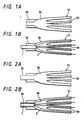
- Figs. 1A and 1B show views for explaining an example of the branch portion of a conventional multi-core optical fiber tape.
- Fig. 1A illustrates the configuration of a multi-branch tube used to form the branch portion and
- Fig. 1B illustrates the configuration of the branch portion.
- a multi-branch tube 31 is constituted by a optical fiber fixing portion 32 which receives and fixes a multi-core optical fiber tape 1, a plurality of single-core optical fiber protection tubes 33 which are disposed on the side opposite to the optical fiber fixing portion 32 so that branched single-core optical fibers 2 are passed therethrough respectively, and a branch portion accommodation space 34 which is formed between the optical fiber fixing portion 32 and the single-core optical fiber protection tubes 33, those portions 32, 33 and 34 being formed integrally with each other.
- the multi-core optical fiber tape 1 is fixed at the vicinity of an end portion thereof in the optical fiber fixing portion 32 of the multi-branch tube 31, and the single-core optical fibers 2 branched from the optical fiber tape 1 are inserted through and protected by the single-core optical fiber protection tubes 33 of the multi-branch tube 31.
- the branch portion is formed.
- Figs. 2A and 2B show views for explaining another example of the branch portion of a conventional multi-core optical fiber tape.
- Fig. 2A illustrates the configuration of a multi-branch tube used to form the branch portion and
- Fig. 2B illustrates the configuration of the branch portion.
- This example is different from the example of Fig. 1A in that a multi-branch tube 31 has no portion for fixing a multi-core optical fiber tape 1 and a protection tube 35 for protecting the multi-core optical fiber tape 1 is integrally formed. Accordingly, the optical fiber tape 1 inserted into the protection tube 35 is not fixed thereat.
- the foregoing conventional branch portion of the multi-core optical fiber tape 1 is a result of contrivance as to a manner how to make the multi-core optical fiber tape 1 branch into plurality of the single-core optical fibers 2 not to be too extreme, and the branch portion is designed in consideration of the arrangement of the single-core optical fiber protection tubes 33 so that no force is exerted on the single-core optical fibers 2 in the respective single-core optical fiber protection tubes 33.
- the branch portion is however ineffective in protection of the branching out single-core optical fibers 2 in the branch portion accommodation space 34 between the end portion of the optical fiber tape 1 and the single-core optical fiber protection tubes 33.
- a portion of a multi-core optical fiber which is characterized in that a branch portion protector constituted by a perforated member having a plurality of insertion holes formed at the same circumference and a substantially spindle-shaped protector formed integrally with and disposed coaxially with the perforated member is arranged between an end portion of the multi-core optical fiber and the single-core optical fiber protection tubes, and in that the single-core optical fibers branching out from the multi-core optical fiber are passed over the spindle-shaped protector along an outer surface thereof and passed through the insertion holes of the perforated member so as to be inserted through the single-core optical fiber protection tubes respectively.
- a branch portion protector constituted by a perforated member having a plurality of insertion holes formed at the same circumference and a substantially spindle-shaped protector formed integrally with and disposed coaxially with the perforated member is arranged between an end portion of the multi-core optical fiber and the single-core optical fiber protection tubes, and the single-core optical fibers branching out from the multi-core optical fiber are passed over the spindle-shaped protector along an outer surface thereof and passed through the insertion holes of the perforated member so as to be inserted through the single-core optical fiber protection tubes respectively. Accordingly, no excessive bending force or the like is exerted on the branching-out single-core optical fibers.
- branching-out single-core optical fibers and the spindle-shaped protector are fixed to each other with resin or the like, so that it is possible to obtain a branch portion which is more stable with reduced optical loss.
- a plurality of grooves are longitudinally formed in the outer surface of the spindle-shaped protector so as to accommodate the branching-out single-core optical fibers therein, it is possible to obtain a branch portion which is further more stable with reduced optical loss.
- Fig. 3 is a longitudinal sectional view showing an embodiment of the branch portion of the multi-core optical fiber according to the present invention.
- Figs. 4A and 4B show the configuration of the branch portion protector constituted by a spindle-shaped protector and a perforated member formed integrally with the spindle-shaped protector according to the present invention.
- Fig. 4A is a longitudinal sectional view
- Fig. 4B is a side view in the direction of the arrows X - X of Fig. 4A.
- a branch portion protector 10 is arranged between an end portion of a multi-core optical fiber 1 such as a multi-core optical fiber tape, a multi-core optical fiber cord, or the like, and single-core optical fiber protection tubes 15 for protecting single-core optical fibers 2 which branch out from the optical fiber 1 and are inserted through the protection tubes 15.
- a multi-core optical fiber 1 such as a multi-core optical fiber tape, a multi-core optical fiber cord, or the like
- single-core optical fiber protection tubes 15 for protecting single-core optical fibers 2 which branch out from the optical fiber 1 and are inserted through the protection tubes 15.
- the branch portion protector 10 is constituted by a substantially spindle-shaped protector 11 and a perforated member 12 integrally formed with each other, as shown in Figs. 4A and 4B.
- the perforated member 12 has pairs of two kinds of large and small insertion holes 13 and 14 formed on the same circumference, each pair having the small insertion hole 13 and the large insertion hole 14 which communicate with each other axially.
- the substantially spindle-shaped protector 11 is disposed coaxially with the perforated member 12 and has a plurality of grooves 11a formed in the outer surface thereof, if necessary, so as to accommodate therein the branching-out single-core optical fibers 2.
- the small insertion holes 13 are provided to insert the single- core optical fibers 2 therethrough and the large insertion holes 14 are provided to insert the respective ends of the single-core optical fiber protection tubes 15 therein and to fix them thereat.
- the plurality of single-core optical fibers 2 branching out from the multi-core optical fiber 1 are respectively led into the small insertion holes13 of the perforated member 12 along the outer surface of the spindle-shaped protector 11 of the branch portion protector 10 or along the grooves 11a of the outer surface of the spindle-shaped protector 11, and respectively inserted through the single-core optical fiber protection tubes 15 fixed in the respective large insertion holes 14.
- a protection tube 17 is provided so as to envelop the vicinity of the end portion of the multi-core optical fiber 1 and the spindle-shaped protector 11 of the branch portion protector 10.
- the inside of the protection tube 17 is filled with resin 20 so that the single-core optical fibers 2 and the spindle-shaped protector 11 are fixed.
- resin formal resin, UV-setting resin, one-component or two-component resin, or the like, may be used.
- a heat-shrinkable tube may be used as the protection tube such that the inside thereof is filled with a heat-fusible adhesive.
- an external protection tube 19 is provided outside the protection tube 17.
- the multi-core optical fiber 1 is inserted through a protection tube 16 for protection thereof, and one end of the external protection tube 19 is located over a portion of the protection tube 16 and fixed thereat.
- a rubber boot 18 is attached onto the other end of the external protection tube 19 so as to protect the single-core optical fiber protection tubes 15.
- Fig. 5 is a longitudinal sectional view showing another embodiment of the multi-core optical fiber branch portion according to the present invention.
- This embodiment shows the case where fibrous anti-tensile bodies 23 and external coatings 21 and 22 are provided over the single-core optical fiber protection tubes 15 and the multi-core optical fiber protection tube 16 so as to reinforce them.
- the fibrous anti-tensile bodies 23 are led into between the protection tube 17 and the external protection tube 19, and the inside of the external protection tube 19 is filled with resin so that the fibrous anti-tensile bodies 23 are fixed thereat.
- a branch portion durable to tensile force is obtained.
- Fig. 6 is a longitudinal sectional view showing a third embodiment of the multi-core optical fiber branch portion according to the present invention.
- the single-core optical fiber protection tubes 15 and the multi-core optical fiber protection tube 16 are reinforced by the fibrous anti-tensile bodies 23 and the external coatings 21 and 22.
- the fibrous anti-tensile bodies 23 are led onto the protection tube 17, and then a layer of a heat-shrinkable tube 24 or a heat-shrinkable tube 24 having a heat-fusible adhesive 25 in the inside thereof is provided over the protection tube 17 so as to fix the fibrous anti-tensile bodies 23 on the protection tube 17.
- a branch portion durable to tensile force is obtained. Further, it is not necessary to wait till resin is hardened because no resin is poured into the inside unlike the embodiment of Fig. 5. Accordingly, the working time is shortened.
- the branch portion protector constituted by the spindle-shaped protector and the perforated member which are integrally formed with each other is provided between the end portion of the multi-core optical fiber and the single-core optical fiber protection tubes so that no excessive force is exerted on the branching-out single-core optical fibers and the optical loss is stable. Therefore, the multi-core optical fiber branch portion according to the present invention is exceedingly effective when it is used as a branch portion of a optical fiber tape or the like which is introduced into an optical fiber cable to reduce the diameter thereof.
Landscapes
- Physics & Mathematics (AREA)
- General Physics & Mathematics (AREA)
- Optics & Photonics (AREA)
- Mechanical Coupling Of Light Guides (AREA)
- Light Guides In General And Applications Therefor (AREA)
- Cable Accessories (AREA)
Applications Claiming Priority (4)
| Application Number | Priority Date | Filing Date | Title |
|---|---|---|---|
| JP9594389 | 1989-04-14 | ||
| JP95943/89 | 1989-04-14 | ||
| JP217039/89 | 1989-08-22 | ||
| JP1217039A JPH0339911A (ja) | 1989-04-14 | 1989-08-22 | 多心光ファイバ心線の分岐部 |
Publications (2)
| Publication Number | Publication Date |
|---|---|
| EP0392679A1 true EP0392679A1 (de) | 1990-10-17 |
| EP0392679B1 EP0392679B1 (de) | 1995-06-07 |
Family
ID=26437110
Family Applications (1)
| Application Number | Title | Priority Date | Filing Date |
|---|---|---|---|
| EP90303006A Expired - Lifetime EP0392679B1 (de) | 1989-04-14 | 1990-03-20 | Verzweigungsvorrichtung für mehradrige optische Fasern |
Country Status (4)
| Country | Link |
|---|---|
| US (1) | US4989945A (de) |
| EP (1) | EP0392679B1 (de) |
| JP (1) | JPH0339911A (de) |
| AU (1) | AU628515B2 (de) |
Cited By (2)
| Publication number | Priority date | Publication date | Assignee | Title |
|---|---|---|---|---|
| FR2678077A1 (fr) * | 1991-06-24 | 1992-12-24 | Cortaillod Cables Sa | Dispositif d'extremite pour cable optique. |
| WO1995032445A3 (de) * | 1994-05-25 | 1996-01-25 | Klaus Wolter | Kupplungsvorrichtung für lichtwellenleiter |
Families Citing this family (18)
| Publication number | Priority date | Publication date | Assignee | Title |
|---|---|---|---|---|
| DE4024835A1 (de) * | 1990-08-04 | 1992-02-06 | Basf Lacke & Farben | Waessrige beschichtungszusammensetzung, insbesondere zur beschichtung von finish-folien und endloskanten sowie verfahren zum beschichten von finish-folien und endloskanten |
| AU1325292A (en) * | 1991-03-01 | 1992-10-06 | Fibernet Research Pty. Ltd. | Fibre separator |
| US5185840A (en) * | 1991-05-06 | 1993-02-09 | Computer Crafts, Inc. | Branching method for a multi-fiber fiberoptic cable |
| DE4341481C2 (de) * | 1993-12-02 | 1997-09-04 | Siemens Ag | Verzweigungseinrichtung |
| WO1995015509A1 (de) * | 1993-12-02 | 1995-06-08 | Siemens Aktiengesellschaft | Verbindungseinrichtung und verzweigungseinrichtung für lichtwellenleiterkabel |
| US5593310A (en) * | 1993-12-27 | 1997-01-14 | Nihon Plast Co., Ltd. | Cable type electric connector |
| US6442322B1 (en) | 2000-12-22 | 2002-08-27 | Jds Uniphase Corporation | Optical fiber management device |
| WO2006106759A1 (ja) | 2005-04-01 | 2006-10-12 | Nissha Printing Co., Ltd. | 車両用透明アンテナおよびアンテナ付き車両用ガラス |
| KR101025054B1 (ko) | 2005-04-01 | 2011-03-25 | 니폰샤신인사츠가부시키가이샤 | 디스플레이용 투명 안테나 및 안테나 부착 디스플레이용투광성 부재 및 안테나 부착 하우징용 부품 |
| US7270485B1 (en) | 2006-06-23 | 2007-09-18 | Carlyle, Inc. | Device for furcating fiber optic cables |
| US8172465B2 (en) * | 2008-10-17 | 2012-05-08 | Netig Llc | Devices and associated methods for furcating fiber optic cables |
| GB2472014B (en) * | 2009-07-20 | 2011-10-05 | Fibrefab Ltd | Connector device and method for producing a furcated fibre optic cable |
| JP2011237782A (ja) * | 2010-04-13 | 2011-11-24 | Sumitomo Electric Ind Ltd | 光分岐素子及びそれを含む光通信システム |
| US9069152B2 (en) * | 2013-02-28 | 2015-06-30 | Corning Optical Communications LLC | Furcating fiber optic cables without direct coupling of optical fibers to strength members, and related assemblies and methods |
| CN103901567B (zh) * | 2014-04-18 | 2016-05-11 | 四川飞阳科技有限公司 | 光分路器的封装结构及其封装方法 |
| EP3001231B1 (de) | 2014-09-26 | 2018-02-28 | CCS Technology, Inc. | Vorrichtung und Verfahren zur Einführung von Glasfasern in Rohre |
| US10175430B2 (en) | 2016-05-05 | 2019-01-08 | Belden Canada Inc. | Overmoulded furcation assembly with strain relief |
| JP6609577B2 (ja) * | 2017-01-10 | 2019-11-20 | 株式会社フジクラ | 光ファイバコードの製造方法 |
Citations (5)
| Publication number | Priority date | Publication date | Assignee | Title |
|---|---|---|---|---|
| FR2534700A1 (fr) * | 1982-10-19 | 1984-04-20 | Silec Liaisons Elec | Dispositif de separation et de protection de fibres optiques a partir d'un cable optique |
| GB2154760A (en) * | 1984-02-21 | 1985-09-11 | American Telephone & Telegraph | Optical packages including fiber seals |
| DE3531693A1 (de) * | 1985-09-05 | 1987-03-12 | Licentia Gmbh | Adapter zum anpassen von glasfaserkabeln in buendelkonstruktion an solche mit sternstruktur |
| US4737010A (en) * | 1985-10-16 | 1988-04-12 | Les Cables De Lyon | Spreader head for an optical fiber cable |
| US4773726A (en) * | 1985-10-31 | 1988-09-27 | Alps Electric Co., Ltd. | Pusher device for plastic optical fiber |
Family Cites Families (15)
| Publication number | Priority date | Publication date | Assignee | Title |
|---|---|---|---|---|
| US4172746A (en) * | 1976-03-31 | 1979-10-30 | Noane Georges Le | Method for on-site connection of cables with optical fibres |
| FR2346731A1 (fr) * | 1976-03-31 | 1977-10-28 | Lenoane Georges | Procede et appareillage de raccordement sur chantier de cables a fibres optiques |
| US4047797A (en) * | 1976-06-09 | 1977-09-13 | International Telephone And Telegraph Corporation | Fiber optic connector |
| US4339171A (en) * | 1978-02-21 | 1982-07-13 | Bunker Ramo Corporation | Fiber optic cable retainer member |
| US4217028A (en) * | 1978-07-24 | 1980-08-12 | International Telephone And Telegraph Corporation | Fiber optic electromechanical submarine cable termination |
| US4184742A (en) * | 1978-10-26 | 1980-01-22 | International Telephone And Telegraph Corporation | Hermaphroditic fiber optic connector |
| DE3260519D1 (en) * | 1981-04-03 | 1984-09-13 | Lignes Telegraph Telephon | Protection device for open optical fibres at the end of a cable element, cable element with said device, and application of such a cable element |
| FR2520516A1 (fr) * | 1982-01-27 | 1983-07-29 | Silec Liaisons Elec | Dispositif de preparation en nappe des extremites de fibres optiques reparties autour d'une structure a symetrie axiale |
| US4626067A (en) * | 1982-07-29 | 1986-12-02 | Cooper Industries, Inc. | Method of breaking out and terminating fiber optic elements from a multifiber cable |
| JPS59109012A (ja) * | 1982-12-14 | 1984-06-23 | Seiko Instr & Electronics Ltd | マルチ光コネクタ |
| US4589727A (en) * | 1983-08-29 | 1986-05-20 | Thomas & Betts Corporation | Optical fiber retainer |
| US4699462A (en) * | 1985-10-09 | 1987-10-13 | Rca Corporation | Fiber optic cable termination and method for forming same |
| FR2597616B1 (fr) * | 1986-04-17 | 1988-08-05 | Telecommunications Sa | Dispositif et procede d'epanouissement de fibres optiques sortant d'un cable a raccorder |
| US4799760A (en) * | 1988-02-29 | 1989-01-24 | Siecor Corporation | Strain relief apparatus |
| US4884862A (en) * | 1988-10-17 | 1989-12-05 | Minnesota Mining And Manufacturing Company | Fiber optic fan-out module |
-
1989
- 1989-08-22 JP JP1217039A patent/JPH0339911A/ja active Pending
-
1990
- 1990-03-20 EP EP90303006A patent/EP0392679B1/de not_active Expired - Lifetime
- 1990-04-12 US US07/507,995 patent/US4989945A/en not_active Expired - Lifetime
- 1990-04-12 AU AU53250/90A patent/AU628515B2/en not_active Ceased
Patent Citations (5)
| Publication number | Priority date | Publication date | Assignee | Title |
|---|---|---|---|---|
| FR2534700A1 (fr) * | 1982-10-19 | 1984-04-20 | Silec Liaisons Elec | Dispositif de separation et de protection de fibres optiques a partir d'un cable optique |
| GB2154760A (en) * | 1984-02-21 | 1985-09-11 | American Telephone & Telegraph | Optical packages including fiber seals |
| DE3531693A1 (de) * | 1985-09-05 | 1987-03-12 | Licentia Gmbh | Adapter zum anpassen von glasfaserkabeln in buendelkonstruktion an solche mit sternstruktur |
| US4737010A (en) * | 1985-10-16 | 1988-04-12 | Les Cables De Lyon | Spreader head for an optical fiber cable |
| US4773726A (en) * | 1985-10-31 | 1988-09-27 | Alps Electric Co., Ltd. | Pusher device for plastic optical fiber |
Cited By (4)
| Publication number | Priority date | Publication date | Assignee | Title |
|---|---|---|---|---|
| FR2678077A1 (fr) * | 1991-06-24 | 1992-12-24 | Cortaillod Cables Sa | Dispositif d'extremite pour cable optique. |
| EP0520946A1 (de) * | 1991-06-24 | 1992-12-30 | Cables Cortaillod S.A. | Abschlussvorrichtung für ein optisches Kabel |
| WO1995032445A3 (de) * | 1994-05-25 | 1996-01-25 | Klaus Wolter | Kupplungsvorrichtung für lichtwellenleiter |
| US5768459A (en) * | 1994-05-25 | 1998-06-16 | Wolter; Klaus | Optical waveguide coupling device |
Also Published As
| Publication number | Publication date |
|---|---|
| JPH0339911A (ja) | 1991-02-20 |
| EP0392679B1 (de) | 1995-06-07 |
| US4989945A (en) | 1991-02-05 |
| AU628515B2 (en) | 1992-09-17 |
| AU5325090A (en) | 1990-10-18 |
Similar Documents
| Publication | Publication Date | Title |
|---|---|---|
| US4989945A (en) | Branch device for multi-core optical fiber | |
| US4626067A (en) | Method of breaking out and terminating fiber optic elements from a multifiber cable | |
| US5649042A (en) | Pre-connectorized loose tube cable | |
| CN102576135B (zh) | 接头装置及制造分叉纤维光缆的方法 | |
| ES2710111T3 (es) | Recubrimiento de tracción mejorado para jalar un cable de fibra óptica a lo largo de un conducto | |
| US4826277A (en) | Transition of a multiple fiber cable to single fiber cable | |
| US20180031784A1 (en) | Fiber optic connectors and sub-assemblies with strength member retention | |
| KR890004179A (ko) | 광파이버의 스플라이싱 방법 | |
| US7093984B2 (en) | Anchor for fiber optic cable | |
| JP2575383B2 (ja) | テープ状多心光ファイバの接続構造 | |
| JPH06103364B2 (ja) | 光ファイバケーブル用屈曲制限装置 | |
| EP0137667B1 (de) | Halter für optische Fibern | |
| US6101303A (en) | Junction configuration for a multi-conductor optical cable | |
| JP2003322727A (ja) | コネクタ付きケーブルおよび通線方法 | |
| JP3967228B2 (ja) | 光ファイバコードの分岐補強部 | |
| KR100393606B1 (ko) | 팬아웃 블럭용 분기 장치 | |
| JPH01137208A (ja) | テープ状光ファイバ心線 | |
| ES2372821T3 (es) | Anclaje para cable de fibra óptica. | |
| JP2661960B2 (ja) | 多心光コード分岐部 | |
| JPS60185907A (ja) | 光フアイバ保護部材 | |
| JP3885477B2 (ja) | 多心光テープファイバコードの分岐部 | |
| JP2004085704A (ja) | 光ファイバコードの分岐補強部 | |
| JP3006595B1 (ja) | 金属管型光ファイバケーブルの光コネクタ付き端末部 | |
| JP4928220B2 (ja) | 光ファイバ用擬似コードの端末処理構造、及び当該擬似コードの保持体並びに光ファイバ接続用簡易端末処理構造体 | |
| JP2003185896A (ja) | 光ファイバテープ心線の変換部構造 |
Legal Events
| Date | Code | Title | Description |
|---|---|---|---|
| PUAI | Public reference made under article 153(3) epc to a published international application that has entered the european phase |
Free format text: ORIGINAL CODE: 0009012 |
|
| AK | Designated contracting states |
Kind code of ref document: A1 Designated state(s): FR GB IT SE |
|
| 17P | Request for examination filed |
Effective date: 19901031 |
|
| 17Q | First examination report despatched |
Effective date: 19920316 |
|
| GRAA | (expected) grant |
Free format text: ORIGINAL CODE: 0009210 |
|
| RIN1 | Information on inventor provided before grant (corrected) |
Inventor name: OHKURA, TOSHIHIKO, C/O YOKOHAMA WORKS OF SUMITOMO |
|
| AK | Designated contracting states |
Kind code of ref document: B1 Designated state(s): FR GB IT SE |
|
| ITF | It: translation for a ep patent filed | ||
| ET | Fr: translation filed | ||
| PLBE | No opposition filed within time limit |
Free format text: ORIGINAL CODE: 0009261 |
|
| STAA | Information on the status of an ep patent application or granted ep patent |
Free format text: STATUS: NO OPPOSITION FILED WITHIN TIME LIMIT |
|
| 26N | No opposition filed | ||
| REG | Reference to a national code |
Ref country code: GB Ref legal event code: IF02 |
|
| PGFP | Annual fee paid to national office [announced via postgrant information from national office to epo] |
Ref country code: SE Payment date: 20030306 Year of fee payment: 14 |
|
| PGFP | Annual fee paid to national office [announced via postgrant information from national office to epo] |
Ref country code: FR Payment date: 20030310 Year of fee payment: 14 |
|
| PGFP | Annual fee paid to national office [announced via postgrant information from national office to epo] |
Ref country code: GB Payment date: 20030319 Year of fee payment: 14 |
|
| PG25 | Lapsed in a contracting state [announced via postgrant information from national office to epo] |
Ref country code: GB Free format text: LAPSE BECAUSE OF NON-PAYMENT OF DUE FEES Effective date: 20040320 |
|
| PG25 | Lapsed in a contracting state [announced via postgrant information from national office to epo] |
Ref country code: SE Free format text: LAPSE BECAUSE OF NON-PAYMENT OF DUE FEES Effective date: 20040321 |
|
| EUG | Se: european patent has lapsed | ||
| GBPC | Gb: european patent ceased through non-payment of renewal fee |
Effective date: 20040320 |
|
| PG25 | Lapsed in a contracting state [announced via postgrant information from national office to epo] |
Ref country code: FR Free format text: LAPSE BECAUSE OF NON-PAYMENT OF DUE FEES Effective date: 20041130 |
|
| REG | Reference to a national code |
Ref country code: FR Ref legal event code: ST |
|
| PG25 | Lapsed in a contracting state [announced via postgrant information from national office to epo] |
Ref country code: IT Free format text: LAPSE BECAUSE OF NON-PAYMENT OF DUE FEES;WARNING: LAPSES OF ITALIAN PATENTS WITH EFFECTIVE DATE BEFORE 2007 MAY HAVE OCCURRED AT ANY TIME BEFORE 2007. THE CORRECT EFFECTIVE DATE MAY BE DIFFERENT FROM THE ONE RECORDED. Effective date: 20050320 |