EP0392702A1 - Druckeinrichtung mit Druckversatz-Korrekturfunktion beim bidirektionalen Drucken - Google Patents
Druckeinrichtung mit Druckversatz-Korrekturfunktion beim bidirektionalen Drucken Download PDFInfo
- Publication number
- EP0392702A1 EP0392702A1 EP90303369A EP90303369A EP0392702A1 EP 0392702 A1 EP0392702 A1 EP 0392702A1 EP 90303369 A EP90303369 A EP 90303369A EP 90303369 A EP90303369 A EP 90303369A EP 0392702 A1 EP0392702 A1 EP 0392702A1
- Authority
- EP
- European Patent Office
- Prior art keywords
- printing
- head member
- during
- printing head
- movement
- Prior art date
- Legal status (The legal status is an assumption and is not a legal conclusion. Google has not performed a legal analysis and makes no representation as to the accuracy of the status listed.)
- Withdrawn
Links
- 238000007639 printing Methods 0.000 title claims abstract description 212
- 230000033001 locomotion Effects 0.000 claims abstract description 74
- 230000005284 excitation Effects 0.000 claims description 30
- 238000000034 method Methods 0.000 claims description 24
- 230000008569 process Effects 0.000 claims description 7
- 230000007246 mechanism Effects 0.000 claims description 4
- 230000005540 biological transmission Effects 0.000 abstract description 10
- 238000010586 diagram Methods 0.000 description 7
- 238000012545 processing Methods 0.000 description 4
- 230000001105 regulatory effect Effects 0.000 description 4
- 230000001276 controlling effect Effects 0.000 description 3
- 238000012937 correction Methods 0.000 description 2
- 230000003111 delayed effect Effects 0.000 description 2
- 230000002457 bidirectional effect Effects 0.000 description 1
- 230000008859 change Effects 0.000 description 1
- 239000002131 composite material Substances 0.000 description 1
- 238000001514 detection method Methods 0.000 description 1
- 230000006870 function Effects 0.000 description 1
- 239000011159 matrix material Substances 0.000 description 1
- 238000005259 measurement Methods 0.000 description 1
- 238000012986 modification Methods 0.000 description 1
- 230000004048 modification Effects 0.000 description 1
- 238000011179 visual inspection Methods 0.000 description 1
Images


Classifications
-
- B—PERFORMING OPERATIONS; TRANSPORTING
- B41—PRINTING; LINING MACHINES; TYPEWRITERS; STAMPS
- B41J—TYPEWRITERS; SELECTIVE PRINTING MECHANISMS, i.e. MECHANISMS PRINTING OTHERWISE THAN FROM A FORME; CORRECTION OF TYPOGRAPHICAL ERRORS
- B41J19/00—Character- or line-spacing mechanisms
- B41J19/18—Character-spacing or back-spacing mechanisms; Carriage return or release devices therefor
- B41J19/20—Positive-feed character-spacing mechanisms
- B41J19/202—Drive control means for carriage movement
Definitions
- the present invention relates to a printing device, for example, a so-called serial printer which performs printing operations on movement of its reciprocal carriage having a printing head, and more particularly to a printer capable of reciprocal printing.
- the unidirectional printing method comprises the steps of printing letters while moving, i.e., scanning, a carriage in a direction along a printing line of a printing sheet on which printing operations are executed, returning the carriage and feeding up the printing sheet by one line and printing the succeeding printing line of the sheet while moving the carriage likewise in the direction of this line so as to print, e.g. a plurality of printing lines.
- the printing operations during only a forward movement of the carriage out of its reciprocal movement is repeated and the disadvantage is consequently that the printing speed becomes low.
- the carriage has to be reciprocated twice to execute a printing operation for one printing line.
- the printing velocity is accordingly slowed down further.
- the reciprocal printing method for printing letters during the forward and reverse movements of the carriage is such that letters are printed during the reverse movement of the carriage at the same velocity as during the forward movement thereof.
- the printing velocity becomes twice as high as that in the unidirectional printing method.
- the backlash of the driving force transmission system can be understood as a composite of backlash resulting from a loose engagement between the output gears of the carriage driving motor (hereinafter referred to as the carriage motor), an elongation of the drive wire, the lag of the rotor relative to the excitation phase of the carriage motor, for example, stepping motor, etc. in the drive system as a whole.
- the lag of the rotor relative to the excitation phase of the carriage motor causes, as conceptually illustrated in FIGs. 2A and 2B, the actual printing position A.P. to lag by ⁇ L behind an ideal printing position I.P. during the forward movement, as illustrated in FIG. 2A, whereas the lag of the rotor relative to the excitation phase causes the printing position to lag by ⁇ L to the right-hand side during the backward movement when the carriage motor reverses. For this reason, the shifting of the printing position during the reciprocal printing operation is doubled. As for the elongation of the drive wire, the tensile force applied to the carriage during the forward movement is reversed during the backward movement as illustrated in FIGs.
- a first known method comprises the steps of detecting the actual position of the carriage at all times and supplying a printing command when the carriage arrives at the same position during the forward and backward movements in order to make the printing positions coincide with each other during the reciprocal printing operation. More specifically, this method is realised with a printer equipped with a circuit for detecting the carriage position, the circuit comprising a timing fence having a line of minute slits for detecting the moving position of the carriage at all times, and a photo encoder for detecting the moving amount of the carriage relative to the timing fence, whereby letters are printed synchronously with clock pulses produced therefrom.
- a second known method employs programs or the like for use in measuring or computing the backlash of the driving force transmission system of a printer beforehand to make printing timing lagged by the amount of backlash thus uniformly obtained. This method premises that overall backlashes of driving force transmission systems in individual products of printers are substantially the same.
- a third known method employs a means for manually regulating printing timing during either forward or backward printing operations. The manually regulating means is so controlled on the part of the manufacturer to correct any shift in printing position at a point of time a printer is set up after it has been assembled and before it is shipped. An operator is otherwise expected to control the means for regulating the printing timing at the time of its use to visually ensure that a shift in printing position has been corrected before actually printing letters. The user will have to make such an adjustment frequently to secure utmost precision.
- the method introduced as the first example is disadvantageous in that the continuous detection of the actual position of the carriage tends to become costly as it requires the provision of the means for detecting the carriage position including the timing fence, the photo encoder, etc.
- the method of manually controlling the means for regulating printing timing on the part of user, when necessary, in order to visually correct the shifting of the printing position is troublesome as the operator is compelled to perform the complicated adjusting operation.
- a printing device comprising a printing head member movable along a platen member for supporting a printing sheet on which a printing operation is to be executed, said printing head member being capable of executing printing operations during both forward movement and reverse movement thereof and said platen member being drivable to feed the printing sheet by a predetermined amount, said printing device further comprising: driving means for driving said printing head member reciprocally; calculating means for calculating a certain value, during one reciprocal travel of said printing head member, relating to a deflection between two periods respectively required for a forward and a reverse movement of said printing head member; and controlling means for controlling said printing head member, in accordance with said value calculated by said calculating means, so as to execute a printing operation in such a manner that a pair of printing positions, adjacently located along a vertical direction, at which the printing operations are respectively executed during the forward movement and the reverse movement are made near each other in a horizontal direction.
- the invention also provides a correcting device for use in such a printing device and a printing process.
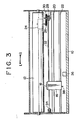
- FIG. 3 is a schematic top view of a printer embodying the present invention.
- a platen 12 is fitted to a frame 10 and driven to rotate by a platen motor 14 shown in FIG. 4.
- a carriage 16 is provided opposite to the platen 12 and loaded with a dot matrix printing head 15. The carriage 16 is supported so that it is movable in parallel to the platen 12 while guided by a pair of guide bars 20, 22.
- a stepping motor as a carriage motor 24 is used for driving the carriage 16 and a gear 26 fixed to the output shaft of the motor 24 is engaged with a gear 30 incorporating a drive pulley 28.
- a drive wire 32 for use in driving the carriage 16 is wound on the drive pulley 28.
- One end of the drive wire 32 is directly fixed to the carriage 16, whereas the other is turned around an auxiliary pulley 34 and fixed to the carriage 16.
- the carriage motor 24 rotates clockwise or counterclockwise, the driving force thereof is transmitted via the gears 26, 30 to the drive pulley 28 and further transmitted from the drive pulley 28 via the wire 32 to the carriage 16.
- the carriage 16 is accordingly reciprocated in the directions of "L” and "R", of FIG. 3. While the carriage 16 is moved by the carriage motor 24 in the direction of "L” or "R" at uniform velocity, the printing head 18 is driven to print a line of letters.
- the platen 12 then feeds up a printing sheet, not shown, so as to make the next line of letters ready for printing.
- a photo-interrupter 36 which functions as a means for detecting the carriage position is fixed to the frame 10 and placed within the shuttle movement of the carriage 16. Although a detailed description of the photo-interrupter 36 is omitted since it is well known, it is an element for detecting the presence or absence of an object between a pair of light-emitting and light-receiving parts set opposite to each other therein.
- a shield 38 is fixed to the carriage 16 and disposed so that it passes between the light-emitting and light-receiving parts of the photo-interrupter 36.
- the shield 38 intercepts the light from the light-emitting part to the light-receiving part, the carriage 16 is detected as being located at the photo-interrupter 36.
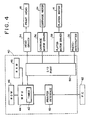
- FIG. 4 is a block diagram illustrating a control system of the printer. What forms the nucleus of this control system is a microcomputer 40, which comprises a MPU (microprocessor unit) 44 having a built-in timer 42, a ROM (Read Only Memory) 46 prestored with programs for use in operating the printer as a whole and correcting a shift in printing position, a RAM (Random Access Memory) 48 for working and data-recording, and an I/O (Input/Output) port 50 for inputting and outputting corresponding control signals.
- MPU microprocessor unit
- ROM Read Only Memory
- RAM Random Access Memory
- I/O Input/Output
- a head drive 54, a carriage motor driver 56 and a platen motor driver 58 in addition to the photo-interrupter 36 are connected to the I/O port 50, whereas the printing head 18, the carriage motor 24 and the platen motor 24 are respectively connected thereto.
- a printer interface 60 is connected to the MPU 44, the printer interface being used for receiving printing data from external equipment such as a P.C. (Personal Computer) 62, a wordprocessor or the like. Even in the case of a wordprocessor or a personal computer in which a printer and a keyboard have been combined together, its control system configuration is substantially the same as what has been referred to above.
- a printing mechanism with the printing head 18 as a principal component in the embodiment shown is arranged so that, as shown in FIG. 5A, a vertical dot train having a pitch of "L" may be printed at a time.
- the printing mechanism is continuously driven while it selects dots and prints characters, figures, etc. composed of dot matrices.
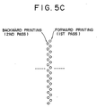
- the printing mechanism is capable of so-called two-pass printing.
- the two-pass printing denotes a printing technique comprising the steps of feeding up paper by an L/2 pitch after printing a dot string once and further printing a dot string to fill up the gap between the dots in order to double the dot density.
- the double printing operation intended to print a line of letters is achieved by giving the first pass during the forward movement and the second pass during the backward one.
- the shifting of the printing position attributed to the backlash of the driving force transmission system e.g. the lag of the rotor relative to the excitation phase of the carriage motor 24, the elongation of the drive wire 32, loose connection between the gears 26, 30, etc.
- the printing position in forward letter-printing at the first pass may not be superposed on that in backward letter-printing at the second pass as shown in FIG. 5C.
- FIG. 6 illustrates the excitation phase of the carriage motor 24 (a stepping motor of four phases ranging from “A" to "D” in this example) and the actual printing position corresponding to the position of the carriage 16.
- the carriage motor 24 a stepping motor of four phases ranging from "A" to "D” in this example
- the actual printing position corresponding to the position of the carriage 16.
- printing of only two lines of dots in tiers is considered and, to simplify the description further, printing of one dot per corresponding step is also considered, though a plurality of dots are normally vertically printed at one step of the carriage motor 24.
- the shifting ⁇ L of the printing position is taken out as time ⁇ t and the printing timing is delayed by that ⁇ ?t during the backward printing operation, whereby it is intended to cancel the shifting of the printing position by printing the dot n on the first dot line and the dot "n" on the second dot line at the vertically corresponding position, i.e. at the same linear position.
- the abscissa axis represents the excitation phase (four phases of "A" - "D") of the carriage motor 24, whereas the ordinate axis represents a position at which the carriage 16 should stop when a given excitation phase is excited.
- an ideal stop position (absolute position) of the carriage 16 is indicated by means of a symbol corresponding to the excitation phase of the carriage motor 24.
- a curve 11 in FIG. 7 shows the relation between the position of the carriage 16 and the motor excitation phase when the carriage motor 24 is driven from the leftmost excitation phase "A" up to the excitation phase "A" (rightmost therein) 8 steps ahead in order to forwardly move the carriage 16 that has been stopped at the leftmost excitation phase "A” therein.
- the reason for the non-correspondence of the carriage position to the excitation phase on that curve is mainly ascribed to the backlash of the driving force transmission system and this is a view of the aforementioned follow-up lag of the carriage 16 from a different angle.
- a curve 12 shows the relation between the motor excitation phase and the actual carriage position when the carriage that has been stopped at the rightmost excitation phase "A" is backwardly moved through a section equivalent to what is to be moved forward.
- the hysteresis of the locus 11 of the carriage during the forward movement and the locus 12 during the backward movement are said to constitute the backlash of the drive system as a whole and the hysteretic range may be considered constant within the range of uniform motion of the carriage 16.
- the aforementioned hysteretic range can be taken out as time data by measuring the hysteretic range in distance as time ⁇ t.
- the hysteretic range may be given as a distance if it is taken in the ordinate direction, it is given as time ⁇ t if it is taken in the abscissa direction.
- a reference drive control point of the carriage motor 24 is set at a point "S", for instance, as shown in FIG. 7.
- the reference drive control point "S” is a point of time at which the phase "D” three steps ahead starts being excited with the leftmost phase “A” as a reference during the forward movement, whereas it is a point of time at which the phase "C” six steps ahead starts being excited with the rightmost phase “A” as a reference during the backward movement.
- the time required t L during the backward movement is smaller than t R during the forward movement and this is because the excitation phase moves to the preceding step while the backlash of the drive system is absorbed.
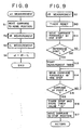
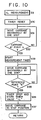
- FIGs. 8 through 10 are flowcharts showing the specific procedures of measuring the t R , t L and computing ⁇ t in the embodiment shown.
- the MPU 44 supplies the carriage driver 56 with a control signal in Step 1 (hereinafter referred to as simply S1 and similar abbreviations shall apply to other steps) when power is turned on and causes the carriage 16 to move up to a home position to the left of the photo-interrupter 36 in FIG. 3 and to stop thereat.
- Step 1 hereinafter referred to as simply S1 and similar abbreviations shall apply to other steps
- S2 and S3 t R , t L are subsequently measured respectively and the difference in transit time therebetween is computed in S4.
- FIG. 9 illustrates a routine in S2 further. More specifically, the timer 42 is reset in S10 after the carriage 16 is moved to the home position on the "L" side in FIG. 3 and the carriage motor 24 is driven at the same constant pulse rate as the printing velocity to move the carriage 16 up to the fixed position on the "R" side in FIG. 3 beyond the photo-interrupter 36.
- the MPU 44 checks up to see if each step position falls on the reference drive control point "S" on a step basis, i.e. on the basis of initial excitation in each excitation phase and, if the step falls on the reference drive control point "S", starts the timer 42 for measuring time in S13 and continues the process of driving the carriage 16 in S14.
- the output of the photo-interrupter 36 is simultaneously checked in S15 and, when the output varies, i.e. when either edge of the shield 38 of the carriage 16 is detected as the output of the photo-interrupter 36 has a pulse-like waveform with a given width, a decision made in S15 becomes "YES".
- the timer 42 is then stopped and the value t R of the timer is stored in the RAM 48.
- the carriage 16 subsequently comes to the fixed position to the "R" of the photo-interrupter 36 of FIG. 3 in S17, the driving of the carriage is stopped and it remains stationary thereat.
- FIG. 10 illustrates a routine for use in measuring the time t L during the forward movement and the processing flow is substantially similar to that of measuring t R .
- the MPU 44 resets the timer 42 in S30 and starts driving the carriage motor 24 at a pulse rate in constantly proportional to the printing velocity in order to move the carriage 16 from the stationary position on the "R" side in FIG. 3 up to what is to the "L" beyond the photo-interrupter 36.
- the output of the photo-interrupter 36 is checked in parallel to the driving of the carriage motor 42 at this time in S32.
- the timer 42 is started in S33 when the edge of the shield 38 on the same side as that during the forward movement at the output pulse is detected and the driving process is continued in S34.
- the shift in printing position is corrected according to the data ⁇ t as a difference in time and, in the embodiment shown in FIG. 6, there is arranged a program for use in delaying the timing of driving the printing head during the backward printing operation by ⁇ t from the head point of time of the phase "C" excitation as the reference drive control point "S".
- the time lag ⁇ t is set to the timer 42 in order that the issuance of a printing command is delayed by the time set to the timer 42 during the backward printing operation.
- the n printing point on the first dot line coincides with that on the second dot line, whereby high-density precision printing can be achieved as shown in FIG. 5B.
- the carriage motor 24 is mainly used as the means for reciprocating the carriage 16 and the timer 42 is mainly used as the means for measuring the transit time
- the programs stored in the ROM 46 and used for correcting shifts in printing position and the MPU 44 for executing the programs are mainly used as means for computing the difference in transit time and correcting the printing timing in the embodiment shown.
Landscapes
- Character Spaces And Line Spaces In Printers (AREA)
- Dot-Matrix Printers And Others (AREA)
Applications Claiming Priority (2)
| Application Number | Priority Date | Filing Date | Title |
|---|---|---|---|
| JP82816/89 | 1989-03-31 | ||
| JP8281689A JPH02261678A (ja) | 1989-03-31 | 1989-03-31 | 往復印字の印字位置ずれ補正機能を有するプリンタ |
Publications (1)
| Publication Number | Publication Date |
|---|---|
| EP0392702A1 true EP0392702A1 (de) | 1990-10-17 |
Family
ID=13784931
Family Applications (1)
| Application Number | Title | Priority Date | Filing Date |
|---|---|---|---|
| EP90303369A Withdrawn EP0392702A1 (de) | 1989-03-31 | 1990-03-29 | Druckeinrichtung mit Druckversatz-Korrekturfunktion beim bidirektionalen Drucken |
Country Status (2)
| Country | Link |
|---|---|
| EP (1) | EP0392702A1 (de) |
| JP (1) | JPH02261678A (de) |
Cited By (3)
| Publication number | Priority date | Publication date | Assignee | Title |
|---|---|---|---|---|
| DE4314904A1 (de) * | 1993-02-26 | 1994-09-01 | Samsung Electronics Co Ltd | Verfahren zum optimalen Steuern eines Wagens für einen seriellen Drucker |
| WO2002009947A1 (en) * | 2000-08-01 | 2002-02-07 | Inca Digital Printers Limited | Timer device for a digital printer and method of printing |
| US7374543B2 (en) | 2003-10-24 | 2008-05-20 | Nihon Seimitsu Sokki Co., Ltd. | Wrist sphygmomanometer and cuff spring for the same |
Families Citing this family (2)
| Publication number | Priority date | Publication date | Assignee | Title |
|---|---|---|---|---|
| JP3248169B2 (ja) * | 1990-05-15 | 2002-01-21 | セイコーエプソン株式会社 | 印字制御装置 |
| EP1287992B1 (de) * | 2001-08-27 | 2009-01-07 | Canon Kabushiki Kaisha | Tintenstrahldruckvorrichtung und Tintenstrahldruckverfahren |
Citations (3)
| Publication number | Priority date | Publication date | Assignee | Title |
|---|---|---|---|---|
| EP0263688A1 (de) * | 1986-10-09 | 1988-04-13 | Oki Electric Industry Company, Limited | Verfahren zum Korrigieren der Druckposition bei einem Punktmatrixseriendrucker |
| US4752144A (en) * | 1984-03-30 | 1988-06-21 | Nec Home Electronics Ltd. | Reciprocative typing control system |
| EP0291099A1 (de) * | 1987-05-15 | 1988-11-17 | Brother Kogyo Kabushiki Kaisha | Apparat zum Markieren einer Ausgangsstellung eines beweglichen Elementes |
-
1989
- 1989-03-31 JP JP8281689A patent/JPH02261678A/ja active Pending
-
1990
- 1990-03-29 EP EP90303369A patent/EP0392702A1/de not_active Withdrawn
Patent Citations (3)
| Publication number | Priority date | Publication date | Assignee | Title |
|---|---|---|---|---|
| US4752144A (en) * | 1984-03-30 | 1988-06-21 | Nec Home Electronics Ltd. | Reciprocative typing control system |
| EP0263688A1 (de) * | 1986-10-09 | 1988-04-13 | Oki Electric Industry Company, Limited | Verfahren zum Korrigieren der Druckposition bei einem Punktmatrixseriendrucker |
| EP0291099A1 (de) * | 1987-05-15 | 1988-11-17 | Brother Kogyo Kabushiki Kaisha | Apparat zum Markieren einer Ausgangsstellung eines beweglichen Elementes |
Non-Patent Citations (1)
| Title |
|---|
| PATENT ABSTRACTS OF JAPAN * |
Cited By (5)
| Publication number | Priority date | Publication date | Assignee | Title |
|---|---|---|---|---|
| DE4314904A1 (de) * | 1993-02-26 | 1994-09-01 | Samsung Electronics Co Ltd | Verfahren zum optimalen Steuern eines Wagens für einen seriellen Drucker |
| WO2002009947A1 (en) * | 2000-08-01 | 2002-02-07 | Inca Digital Printers Limited | Timer device for a digital printer and method of printing |
| US6935722B2 (en) | 2000-08-01 | 2005-08-30 | Inca Digital Printers Limited | Timer device for a digital printer and method of printing |
| US7374543B2 (en) | 2003-10-24 | 2008-05-20 | Nihon Seimitsu Sokki Co., Ltd. | Wrist sphygmomanometer and cuff spring for the same |
| US8292821B2 (en) | 2003-10-24 | 2012-10-23 | Nihon Seimitsu Sokki Co., Ltd. | Wrist sphygmomanometer and cuff spring for the same |
Also Published As
| Publication number | Publication date |
|---|---|
| JPH02261678A (ja) | 1990-10-24 |
Similar Documents
| Publication | Publication Date | Title |
|---|---|---|
| EP0364262B1 (de) | Drucker mit Vorrichtung zum Einstellen der Schlagweite des Kopfes | |
| US5255987A (en) | Paper margin detecting device for use in printing apparatus | |
| EP1043168B1 (de) | Thermodrucker und deren Aufzeichnungsverfahren | |
| EP0659572B1 (de) | Drucker und Verfahren zur Steuerung desselben | |
| EP0392702A1 (de) | Druckeinrichtung mit Druckversatz-Korrekturfunktion beim bidirektionalen Drucken | |
| US4838717A (en) | Serial dot matrix printer | |
| US20070176350A1 (en) | Printer | |
| US5926192A (en) | Print control system | |
| EP0291099A1 (de) | Apparat zum Markieren einer Ausgangsstellung eines beweglichen Elementes | |
| US5803628A (en) | Printing apparatus including encoder pending | |
| US7019481B2 (en) | Carriage driving apparatus and motor control method | |
| US12179475B2 (en) | Dual drive print media conveyor belt | |
| KR960003351B1 (ko) | 위치검출장치 | |
| JP2021041659A (ja) | 駆動システム | |
| US20020021102A1 (en) | DC motor control device and control method | |
| US5018888A (en) | Paper tension adjusting device and method for a printer | |
| US6601513B1 (en) | Motor control method and apparatus, time recorder having same and impact type printing apparatus | |
| JP2005297253A (ja) | 画像形成装置 | |
| EP0290219B1 (de) | Vorrichtung zum Steuern der Wagenbewegung in einem Drucker | |
| JPH0710616B2 (ja) | カラ−リボン切替機構の制御方法 | |
| JPH05278287A (ja) | シリアルドットプリンタ | |
| JPH0439015Y2 (de) | ||
| JPH0257373A (ja) | プリンタ装置 | |
| JPS6274664A (ja) | プリンタの印字開始位置調整装置 | |
| JP3464594B2 (ja) | 記録方法および記録装置 |
Legal Events
| Date | Code | Title | Description |
|---|---|---|---|
| PUAI | Public reference made under article 153(3) epc to a published international application that has entered the european phase |
Free format text: ORIGINAL CODE: 0009012 |
|
| AK | Designated contracting states |
Kind code of ref document: A1 Designated state(s): DE FR GB |
|
| STAA | Information on the status of an ep patent application or granted ep patent |
Free format text: STATUS: THE APPLICATION IS DEEMED TO BE WITHDRAWN |
|
| 18D | Application deemed to be withdrawn |
Effective date: 19910418 |