EP0392814A2 - Überwachungsapparat für eine Mehrfarbendruckpresse - Google Patents
Überwachungsapparat für eine Mehrfarbendruckpresse Download PDFInfo
- Publication number
- EP0392814A2 EP0392814A2 EP90303887A EP90303887A EP0392814A2 EP 0392814 A2 EP0392814 A2 EP 0392814A2 EP 90303887 A EP90303887 A EP 90303887A EP 90303887 A EP90303887 A EP 90303887A EP 0392814 A2 EP0392814 A2 EP 0392814A2
- Authority
- EP
- European Patent Office
- Prior art keywords
- web
- monitoring apparatus
- colour
- camera
- television camera
- Prior art date
- Legal status (The legal status is an assumption and is not a legal conclusion. Google has not performed a legal analysis and makes no representation as to the accuracy of the status listed.)
- Withdrawn
Links
- 238000012544 monitoring process Methods 0.000 title claims abstract description 18
- 238000007639 printing Methods 0.000 title claims abstract description 15
- 239000003086 colorant Substances 0.000 claims abstract description 10
- 230000001360 synchronised effect Effects 0.000 claims abstract description 3
- 230000003287 optical effect Effects 0.000 claims description 9
- 230000000007 visual effect Effects 0.000 claims description 3
- 238000005259 measurement Methods 0.000 claims 2
- 239000000976 ink Substances 0.000 description 21
- 238000010586 diagram Methods 0.000 description 5
- 230000002250 progressing effect Effects 0.000 description 2
- 230000000694 effects Effects 0.000 description 1
- 239000000463 material Substances 0.000 description 1
- 238000007645 offset printing Methods 0.000 description 1
- 238000001228 spectrum Methods 0.000 description 1
- 239000004753 textile Substances 0.000 description 1
Images

Classifications
-
- B—PERFORMING OPERATIONS; TRANSPORTING
- B41—PRINTING; LINING MACHINES; TYPEWRITERS; STAMPS
- B41F—PRINTING MACHINES OR PRESSES
- B41F33/00—Indicating, counting, warning, control or safety devices
- B41F33/0036—Devices for scanning or checking the printed matter for quality control
Definitions
- This invention relates to colour printing in a web-fed printing press and more particularly to an apparatus which can monitor the ink density levels of different colours at selected points on the web being printed upon.
- a monitoring apparatus for use in a colour printing press, comprising a head which includes a colour television camera directed at a web moving through the press, a strobed source of light of broad bandwidth for illuminating the web and synchronised with the movement of the web, means for inserting any of a plurality of different coloured filters in the light path to the camera, and a circuit for responding to the luminance output signal from the camera to monitor the ink density on the web at colours corresponding to the selected filters.
- the head is mounted for movement across the width of the moving web, so that the apparatus may examine the web at any selected point across its width.
- the timing of the strobed source of light may be adjusted for examining any selected point lengthwise of the web and therefore any selected point of the successive copies being printed on the web can be monitored.
- the colour television camera is preferably included in a close circuit television system, the colour monitor of which provides a visual display of the selected region of the work being printed. When none of the coloured filters is inserted in the light path to the camera, the colour monitor then provides a still display of the selected region of the work being printed, to enable an immediate visual examination of the copies as they are being printed.
- the luminance output signal from the camera gives a measure of the ink density at the corresponding colour.
- This signal may be used to drive a digital read-out and the reading on this can be used, by the operator to adjust manually the ink ducts for the relevant colour ink.
- the signal may be used in a closed loop feedback system to adjust the ink ducts automatically.
- a zoom lens unit is positioned in front of the colour television camera, so that the camera may be focussed onto any selected size of area on the web.
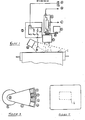
- a web 1 of paper is moving lengthwise of itself through the press and over a roller 2.
- the monitoring apparatus in accordance with this invention includes a head which is mounted for movement across the width of the web, i.e. in a direction parallel to the axis of the roller 2.
- the head includes a colour television camera D which is directed at the web 1 as it passes over the roller 2, the camera D supplying a chrominance signal B and a luminance signal C in accordance with known principles.
- a zoom lens unit G is positioned in front of the camera D and a filter quadrant F is disposed between the zoom lens unit G and the camera D.
- the filter quadrant F is mounted to the drive shaft of a stepping motor E, and comprises ( Figure 3) a quadrant plate W having four windows along its outer edge, mounting blue, green, red and clear filters S,T, U and V.
- the moving head of the monitoring apparatus also includes a strobe lamp H which directs white light onto the web 1 to illuminate the area viewed by the camera D through the zoom lens unit G.
- an optical system I is included to provide reference signals with which the luminance output can be compared.
- the optical system I comprises a beam splitter 0 positioned in the light beam from the strobe lamp H, to project a portion of this beam into the system I through a lens N ( Figure 2).
- the system I includes an arrangement of beam splitters M0, M1, M2 for directing portions of the received light beam onto respective photo diodes J0, J1, J2, J3. Red, green and blue filters are positioned in front of the photo diodes J1, J2 and J3.
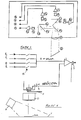
- the signals from the photo diodes are passed to respective amplifiers K0 - K3 which provide output signals P0, P, Q and R representing full spectrum, red, green and blue reference levels.
- the output luminance signal from the colour television camera is connected to one input of a comparator 3, which includes a sample and hold circuit, whilst the output signals P0, P, Q and R from the optical reference system are connected to the other input of the comparator via respective switches 4.
- the colour television camera D is included in a closed circuit television system, its output signals B and C being used to drive a colour monitor 5 ( Figure 5).
- the colour monitor 5 can display any selected area of the work being printed on the web 1 in successive copies: the required area is selected by moving the head across the web to the desired point, and altering the timing of the strobe lamp H.
- the size of the area being examined may be adjusted using the zoom lens unit G.
- the monitoring apparatus may be used to focus on each of these different colour regions in turn, then by driving the stopper motor E to place the appropriate colour filter in front of the television camera D, the ink density of the relevant colour ink can be measured.
- the red filter U also the output signal P from the optical reference system is selected by the respective switch 4 and applied to the comparator 3.
- the luminance output signal C from the television camera is inversely proportional to the density of ink on the web 1 and is referenced by comparator 3 to the signal P and hence to the luminous intensity of the strobe lamp H.
- the comparator 3 may drive a digital read out and the operator may use the reading on this to decide whether any adjustment is needed to the ink ducts providing ink of the respective colours to the ink rollers of the press.
- the comparator outputs may be used in a closed loop system to adjust automatically the ink ducts for the respective colours.
- the filter quadrant plate W may be extended and have four fourther similar coloured windows as shown in Figure 7.
- the colour monitor is preferably marked with a rectangular field of view 6.
- the zoom lens G can be adjusted so that an area on the web which is being viewed fills the field of view 6 on the colour monitor.
- the output from the Comparator 3 can then be gated by a signal derived from the horizontal and vertical scanning signals, so as to be passed only in respect of the field of view 6, and the output from the gate 7 can be averaged.
- the monitoring apparatus which has been described enables any selected area of the work being printed to be viewed on the colour monitor whilst printing is progressing. It further enables the ink density of the different colours to be measured whilst printing is progressing and therefore enables any necessary adjustments to the respective ink flow rates to be made without delay.
- the apparatus may be used on printing presses printing on paper, textile or any other material.
Landscapes
- Engineering & Computer Science (AREA)
- Quality & Reliability (AREA)
- Inking, Control Or Cleaning Of Printing Machines (AREA)
Applications Claiming Priority (2)
| Application Number | Priority Date | Filing Date | Title |
|---|---|---|---|
| GB898908271A GB8908271D0 (en) | 1989-04-12 | 1989-04-12 | Monitoring apparatus for colour printing press |
| GB8908271 | 1989-04-12 |
Publications (2)
| Publication Number | Publication Date |
|---|---|
| EP0392814A2 true EP0392814A2 (de) | 1990-10-17 |
| EP0392814A3 EP0392814A3 (de) | 1991-07-17 |
Family
ID=10654898
Family Applications (1)
| Application Number | Title | Priority Date | Filing Date |
|---|---|---|---|
| EP19900303887 Withdrawn EP0392814A3 (de) | 1989-04-12 | 1990-04-11 | Überwachungsapparat für eine Mehrfarbendruckpresse |
Country Status (2)
| Country | Link |
|---|---|
| EP (1) | EP0392814A3 (de) |
| GB (1) | GB8908271D0 (de) |
Cited By (5)
| Publication number | Priority date | Publication date | Assignee | Title |
|---|---|---|---|---|
| DE4237004A1 (de) * | 1992-11-02 | 1994-05-05 | Mohndruck Reinhard Mohn Ohg | Verfahren zur Online-Farbregelung von Druckmaschinen |
| WO1995000335A1 (de) * | 1993-06-25 | 1995-01-05 | Heidelberger Druckmaschinen Ag | Vorrichtung zur parallelen bildinspektion und farbregelung an einem druckprodukt |
| DE4401535A1 (de) * | 1994-01-20 | 1995-07-27 | Heidelberger Druckmasch Ag | Verfahren zum Abtasten von im Mehrfarbendruck erzeugten Registermarken |
| EP0798117A3 (de) * | 1996-03-27 | 1998-03-18 | Advanced Vision Technology Ltd. | Vorrichtung und Verfahren zur Farbmessung und Farbkontrolle während des Bedruckens in einer Druckmaschine |
| WO2008122443A1 (de) * | 2007-04-10 | 2008-10-16 | Wifag Maschinenfabrik Ag | Verfahren zum messen der farbqualität im rollendruck |
Family Cites Families (6)
| Publication number | Priority date | Publication date | Assignee | Title |
|---|---|---|---|---|
| DE2011979A1 (de) * | 1970-03-13 | 1972-04-13 | Reinhard C Otto & Cie | Verfahren und Vorrichtung zur Steuerung von Druckmaschinen |
| EP0127831B1 (de) * | 1983-06-02 | 1990-03-14 | Web Printing Controls Co. | Registerregelung in geschlossener Schleife |
| DE3322665A1 (de) * | 1983-06-23 | 1985-01-03 | Siemens AG, 1000 Berlin und 8000 München | Farbdichtemessgeraet |
| EP0177885A3 (de) * | 1984-10-03 | 1988-02-24 | Dai Nippon Insatsu Kabushiki Kaisha | Verfahren und Vorrichtung zum Einstellen des Registers in Druckpressen |
| EP0196431B1 (de) * | 1985-03-21 | 1992-11-11 | Felix Brunner | Verfahren, Regelvorrichtung und Hilfsmittel zur Erzielung eines gleichförmigen Druckresultats an einer autotypisch arbeitenden Mehrfarbenoffsetdruckmaschine |
| DD240174A1 (de) * | 1985-08-13 | 1986-10-22 | Polygraph Leipzig | Einrichtung zur passerermittlung |
-
1989
- 1989-04-12 GB GB898908271A patent/GB8908271D0/en active Pending
-
1990
- 1990-04-11 EP EP19900303887 patent/EP0392814A3/de not_active Withdrawn
Cited By (8)
| Publication number | Priority date | Publication date | Assignee | Title |
|---|---|---|---|---|
| DE4237004A1 (de) * | 1992-11-02 | 1994-05-05 | Mohndruck Reinhard Mohn Ohg | Verfahren zur Online-Farbregelung von Druckmaschinen |
| WO1995000335A1 (de) * | 1993-06-25 | 1995-01-05 | Heidelberger Druckmaschinen Ag | Vorrichtung zur parallelen bildinspektion und farbregelung an einem druckprodukt |
| DE4321177A1 (de) * | 1993-06-25 | 1995-01-05 | Heidelberger Druckmasch Ag | Vorrichtung zur parallelen Bildinspektion und Farbregelung an einem Druckprodukt |
| US5724437A (en) * | 1993-06-25 | 1998-03-03 | Heidelberger Druckmaschinen Ag | Device for parallel image inspection and inking control on a printed product |
| DE4401535A1 (de) * | 1994-01-20 | 1995-07-27 | Heidelberger Druckmasch Ag | Verfahren zum Abtasten von im Mehrfarbendruck erzeugten Registermarken |
| DE4401535C2 (de) * | 1994-01-20 | 2002-10-24 | Heidelberger Druckmasch Ag | Verfahren zum Abtasten von im Mehrfarbendruck erzeugten Registermarken |
| EP0798117A3 (de) * | 1996-03-27 | 1998-03-18 | Advanced Vision Technology Ltd. | Vorrichtung und Verfahren zur Farbmessung und Farbkontrolle während des Bedruckens in einer Druckmaschine |
| WO2008122443A1 (de) * | 2007-04-10 | 2008-10-16 | Wifag Maschinenfabrik Ag | Verfahren zum messen der farbqualität im rollendruck |
Also Published As
| Publication number | Publication date |
|---|---|
| EP0392814A3 (de) | 1991-07-17 |
| GB8908271D0 (en) | 1989-05-24 |
Similar Documents
| Publication | Publication Date | Title |
|---|---|---|
| US7860278B2 (en) | Measuring color on a moving substrate | |
| US5774225A (en) | System and method for color measurement and control on-press during printing | |
| DE69814224T2 (de) | Methode zur Steuerung des Feuchtmittels in einer Druckmaschine | |
| US7884926B2 (en) | Color measuring apparatus having differently operating measuring devices | |
| DE69720161T2 (de) | Verfahren und Vorrichtung zur Überwachung der Druckqualität | |
| EP1470918A2 (de) | Vorrichtung und Verfahren zur Farbmessung in einer Druckmaschine | |
| DE4321179A1 (de) | Verfahren und Einrichtung zur Steuerung oder Regelung von Betriebsvorgängen einer drucktechnischen Maschine | |
| GB2064113A (en) | Monitoring Colour of Printed Web | |
| US6715945B2 (en) | Printing apparatus for performing quality control of printed paper sheet | |
| DE102004003613A1 (de) | Vorrichtung und Erfassung eines Bildes von einem vorbestimmten Ausschnitt eines in Bewegung befindlichen Druckerzeugnisses | |
| DE19836337C1 (de) | Vorrichtung und Verfahren zum Belichten von Bildinformationen auf lichtempfindliches Aufzeichnungsmaterial | |
| DE102007030571A1 (de) | Farbmessvorrichtung mit zwei unterschiedlich arbeitenden Messeinrichtungen | |
| JPH0469068B2 (de) | ||
| EP1579994B1 (de) | Druckmaschine mit einem Inline-Inspektionssystem | |
| EP0787283B1 (de) | Methode zur farbmessung während des druckens mit bestätigung | |
| EP1543354B1 (de) | Verfahren und vorrichtung zur optischen inspektion eines substrats auf einer druckpresse | |
| DE69016486T2 (de) | Fotografisches Kopiergerät. | |
| EP1551635B1 (de) | Verfahren und vorrichtung zur online-überwachung von druckqualität | |
| EP0392814A2 (de) | Überwachungsapparat für eine Mehrfarbendruckpresse | |
| EP0921381A2 (de) | Optischer Farbsensor | |
| EP1584471B1 (de) | Verfahren und Vorrichtung um einen Druckträger einer Druckmaschine visuell zu inspizieren | |
| US3419677A (en) | Apparatus for monitoring high speed processes | |
| US4678336A (en) | Apparatus for detecting image area of thin plate | |
| EP3922984A1 (de) | Beleuchtungsvorrichtung und inspektionsvorrichtung | |
| JPS59128418A (ja) | 印刷物検査装置 |
Legal Events
| Date | Code | Title | Description |
|---|---|---|---|
| PUAI | Public reference made under article 153(3) epc to a published international application that has entered the european phase |
Free format text: ORIGINAL CODE: 0009012 |
|
| AK | Designated contracting states |
Kind code of ref document: A2 Designated state(s): DE FR GB |
|
| PUAL | Search report despatched |
Free format text: ORIGINAL CODE: 0009013 |
|
| AK | Designated contracting states |
Kind code of ref document: A3 Designated state(s): DE FR GB |
|
| STAA | Information on the status of an ep patent application or granted ep patent |
Free format text: STATUS: THE APPLICATION IS DEEMED TO BE WITHDRAWN |
|
| 18D | Application deemed to be withdrawn |
Effective date: 19920118 |