EP0392842A1 - Ballonpresse/Verdichtungsmaschine - Google Patents
Ballonpresse/Verdichtungsmaschine Download PDFInfo
- Publication number
- EP0392842A1 EP0392842A1 EP90303952A EP90303952A EP0392842A1 EP 0392842 A1 EP0392842 A1 EP 0392842A1 EP 90303952 A EP90303952 A EP 90303952A EP 90303952 A EP90303952 A EP 90303952A EP 0392842 A1 EP0392842 A1 EP 0392842A1
- Authority
- EP
- European Patent Office
- Prior art keywords
- door
- machine
- hydraulic
- baler
- compactor
- Prior art date
- Legal status (The legal status is an assumption and is not a legal conclusion. Google has not performed a legal analysis and makes no representation as to the accuracy of the status listed.)
- Withdrawn
Links
- 239000000463 material Substances 0.000 claims description 8
- 239000002699 waste material Substances 0.000 abstract description 8
- 238000005056 compaction Methods 0.000 description 3
- 241000282472 Canis lupus familiaris Species 0.000 description 1
- 238000006243 chemical reaction Methods 0.000 description 1
- 230000008878 coupling Effects 0.000 description 1
- 238000010168 coupling process Methods 0.000 description 1
- 238000005859 coupling reaction Methods 0.000 description 1
- 239000012530 fluid Substances 0.000 description 1
- 239000002184 metal Substances 0.000 description 1
- 230000004048 modification Effects 0.000 description 1
- 238000012986 modification Methods 0.000 description 1
- 230000003068 static effect Effects 0.000 description 1
Images


Classifications
-
- B—PERFORMING OPERATIONS; TRANSPORTING
- B30—PRESSES
- B30B—PRESSES IN GENERAL
- B30B9/00—Presses specially adapted for particular purposes
- B30B9/30—Presses specially adapted for particular purposes for baling; Compression boxes therefor
- B30B9/3057—Fluid-driven presses
-
- B—PERFORMING OPERATIONS; TRANSPORTING
- B30—PRESSES
- B30B—PRESSES IN GENERAL
- B30B9/00—Presses specially adapted for particular purposes
- B30B9/30—Presses specially adapted for particular purposes for baling; Compression boxes therefor
- B30B9/3003—Details
-
- B—PERFORMING OPERATIONS; TRANSPORTING
- B30—PRESSES
- B30B—PRESSES IN GENERAL
- B30B9/00—Presses specially adapted for particular purposes
- B30B9/30—Presses specially adapted for particular purposes for baling; Compression boxes therefor
- B30B9/3003—Details
- B30B9/3032—Press boxes
-
- B—PERFORMING OPERATIONS; TRANSPORTING
- B30—PRESSES
- B30B—PRESSES IN GENERAL
- B30B9/00—Presses specially adapted for particular purposes
- B30B9/30—Presses specially adapted for particular purposes for baling; Compression boxes therefor
- B30B9/3042—Containers provided with, or connectable to, compactor means
- B30B9/3046—Containers with built-in compactor means
Definitions
- This invention relates to baler compactor.
- Such machines are well known and are used for compressing waste such as cardboard, paper, plastic items or tins etc. into compact units for making into bales or bagging prior to disposal.
- the machines vary in size but are normally static, often bolted to a floor. They carry a hydraulic press and power pack having a self contained electric motor control to operate the press and are plugged in to a nearby electrical source.
- a disadvantage of such machines is that the waste to be baled or bagged has to be brought to the machine.
- Another disadvantage is the need to install a power pack to operate the hydraulic system of the machine.
- An object of this invention is to obviate or mitigate the aforementioned disadvantages.
- baler/compactor machine which is connectable to a vehicle for transporting to different areas within a site and wherein the hydraulically operated press is connectable directly to hydraulic controls of the vehicle.
- the baler/compactor machine has a base adapted to receive the forks of a fork lift truck, and hydraulic hoses adapted for connection to an hydraulic supply of the fork lift truck for operation of the hydraulic press.
- the machine has a container body at one end of which is a compacting means extendable into the body to compact material contained therein into a compacted mass and an openable door for removal of the compacted mass.
- the openable door is at the opposite end of the body.
- the openable door is a side wall of the body.
- the machine may be carried in an upright or substantially horizontal disposition by the fork lift vehicle.
- the compacting means is mounted on a pivotal frame which can pivot the compacting means away from the end of the body to enable material to be placed in the body.
- They hydraulic system includes safety means to allow actuation of the compacting means only when the compacting means is correctly positioned relative to the end of the body.
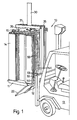
- the baler/compactor machine 10 has a pair of fork sockets 11 to receive the forks 13 of a fork lift truck 13.
- Fig. 1 the machine carries an upright safety guard 14 and a top guard plate 15 both of which are omitted from the other views.
- the machine 10 has an upright open topped container 20 having internal bracing, shown generally at 21 and a drop bottom door 22 in its base.
- the door 22 is normally held closed by an hydraulic actuator 23 and also by a latch 24 which is released preparatory to the actuator allowing the door to open.
- the latch 24 comprises a spring loaded bolt 25 attached to the underside of the door at the front end of the machine, remote from the door pivot 16 at the rear end of the machine, and a latch keep 27 which is welded to a pivot bar 28 of a hand lever 29.
- the lever 29 is located at one side of the container and extends upwards, passing through a guide 29′.
- the lever pivots the latch keep 27 out of engagement with the spring loaded bolt 25 as described more fully hereinafter.
- an hydraulic press actuator in the form of a cylinder 30 is mounted on the cross bar 31 of a pivotal frame 32 and has a downwardly extending piston which carries a platten 33.
- This actuator provides the pressure to enable the platten 33 to compact waste material loaded within the container 20.
- the platten 33 has guide wings 34 or bearings to facilitate entry into the container, the internal bracing 21 providing a location for the guide wings.
- the guide wings 34 or bearings provide stability and load reaction should the platten encounter any incompressible debris or even uneven waste loading.
- the portal frame 32 includes a pair of upright arms 35 connected at their upper ends to the crossbar 31 and pivotally mounted at the sides of the container adjacent to the base thereof.
- the arms 35 are pivotal to one side of the container to an angle of, e.g. 23° in order to uncover the open top and allow material to be dropped in to the container for compacting.
- Stop members 37, 38 are provided to limit the pivotal movement of the arms in each direction and an hydraulic actuator 23 is provided to pivot the arms 35.
- This actuator 23 also operates the door 22. When the door is latched by latch 24, expansion of the actuator 23 will raise the portal frame to the vertical and retraction will pivot the portal frame to one side. When the door is unlatched, and with the pivotal frame in the upright position, expansion of the actuator will allow the door to open, and retraction will raise the door to the closed position.
- an interlock mechanism 39/40 is provided to ensure that the door can only be unlatched when the portal frame is in the upright posiion and also to ensure that the portal frame cannot swing to one side when the door is unlatched.
- the interlock mechanism comprises a pawl 39 at the upper end of the latch keep 27 and an abutment plate 40 on the underside of the adjacent arm 35 and located above the pawl 39.
- the pawl and plate are normally out of engaement, but when the latch keep 27 is pivoted to its unlatched position, the pawl and plate engage.
- the latch keep 27 is held in the unlatched position, - the hand lever 29 returns to its original position by spring pressure - and the portal frame is held in the upright position.
- the pivotal end of the bottom drop door 22 extends beyond one side wall of the container and the door pivot 26 is carried on a pair of brackets 45 welded to that side wall.
- a clevis bracket 46 is welded to the upper surface of that extended part of the door and pivotally carries one end of the actuator 23, the other end of which is attached to a bracket 47 on the adjacent swing arm 35. When the actuator 3 is extended, the door will pivot downwards and the clevis bracket 46 will rotate about the actuator connection.
- the hydraulic actuators which control movement of the platten actuation cylinder 30 and the combined swing arm and door actuation cylinder 23 are pressurised from an auxiliary hydraulic supply 50 of a fork lift truck 13.
- the hydraulic supply includes a pair of nozzles 53 to which flexible hoses 54 are attached by quick release couplings to valve 51 of the hydraulic supply 50.
- These hoses 54 are connected to metal pipes 55 which run along the inside of one arm 35 (omitted from Fig. 1) to the platten actuation cylinder 30 and to the door/swing arm cylinder 23.
- the bales/compactor machine is carried by a form lift truck to various sites where waste material is to be found.
- the hydraulic hoses 54 are coupled to the truck's auxiliary supply 50 and the portal frame 32 is in the swung-to-one-side position to facilitate loading.
- the portal frame is swung to the vertical and the material in the container 20 is compressed to make room for more material, after which the portal frame is swung to the side again.
- the fork lift truck 13 When the container 20 is full or when it is to be emptied, the fork lift truck 13 carries it to the disposal area.
- the pivotal frame 32 is raised to the upright position and the latch 24 is released manually via the hand lever 29.
- baler/compactor machine is then, if necessary raised by the fork lift truck so that the door 22, when released, can fully open.
- the door actuator 23 and the compaction cylinder 30 are both actuated so that the compaction cylinder 30 pushes the compacted waste out of the container and the door actuator allows the door to drop open.
- the compaction cylinder and door actuator can then reverse to raise the platten and draw the door upwards until the spring urged bolt 25 engages with the latch keep 27 which is released by disengagement of the pawl and the interlock plate when the actuators are reversed.
- the container 20 may be provided with standard baler/compactor features, not shown, such as 'dogs' to prevent a compacted mass expanding upwards, and slots and grooves to enable baler twine to be passed round the compacted mass within the container.
- the baler/compactor machine is of the horizontal type with the container disposed fore and aft when carried by the fork lift truck.
- a platten is located at the rear of the container for movement in and out and a horizontal ram is provided to move the platten in and out.
- An exit door is provided at the front end of the container and a loading hopper door in the top of the container.
- the ram is telescopic so that it can push the platten to the front end and so also to restrict the length of the ram rearwardly of the container toward the truck.
- the hydraulic system ensures that the hopper door cannot open when the platten ram is capable of forward motion.
- the ram retracts, the hopper door opens or becomes openable automatically or hydraulically.
- the door is closed fluid pressure is fed to the ram so that it can be moved forward on command.
- the baler/compactor machine is of a standard type having an upright, open topped container 60 and a door front 61 which is hinged to one side wall and latched to the other side wall by pivotal latches 62.
- Material is compacted by a vertical hydraulic press 63 comprising a platten (not shown) located behind a shield 64, a pair of vertical rams 65 transversely disposed and a central support pillar 66 passing through a transverse support frame 67 which is pivotally mounted on a pillar 68 on the hinged side of the container.
- Standard fittings within the container co-operate when the door is opened to tip the compacted mass out of the container.
- the machine although otherwise standard has fork sockets 69 and can be carried by a fork lift truck 70 and the vertical press 63 is actuated from the truck's auxiliary hydraulic supply 71 via flexible hoses 72.
Landscapes
- Engineering & Computer Science (AREA)
- Mechanical Engineering (AREA)
- Refuse-Collection Vehicles (AREA)
Applications Claiming Priority (2)
| Application Number | Priority Date | Filing Date | Title |
|---|---|---|---|
| GB8908111 | 1989-04-11 | ||
| GB898908111A GB8908111D0 (en) | 1989-04-11 | 1989-04-11 | Baler/compactor |
Publications (1)
| Publication Number | Publication Date |
|---|---|
| EP0392842A1 true EP0392842A1 (de) | 1990-10-17 |
Family
ID=10654793
Family Applications (1)
| Application Number | Title | Priority Date | Filing Date |
|---|---|---|---|
| EP90303952A Withdrawn EP0392842A1 (de) | 1989-04-11 | 1990-04-11 | Ballonpresse/Verdichtungsmaschine |
Country Status (2)
| Country | Link |
|---|---|
| EP (1) | EP0392842A1 (de) |
| GB (2) | GB8908111D0 (de) |
Cited By (6)
| Publication number | Priority date | Publication date | Assignee | Title |
|---|---|---|---|---|
| FR2682362A1 (fr) * | 1991-10-14 | 1993-04-16 | Bricaud Martine | Benne pivotante. |
| WO2000059714A1 (en) * | 1999-03-23 | 2000-10-12 | Leif Hall | A device for the compaction of bulky material such as packaging material, especially cartons |
| US7069848B2 (en) * | 2004-06-14 | 2006-07-04 | Brees Theodore H | Mobile apparatus for crushing containers |
| EP3385453B1 (de) | 2017-04-05 | 2022-08-10 | MTS Schrode AG | Bodenrecycler |
| US11453188B2 (en) | 2018-04-30 | 2022-09-27 | Sebright Products, Inc. | Biased retainer assembly for waste container |
| US12545000B1 (en) | 2022-05-02 | 2026-02-10 | Marathon Equipment Company | Bale weighing system |
Citations (4)
| Publication number | Priority date | Publication date | Assignee | Title |
|---|---|---|---|---|
| AU2265867A (en) * | 1967-05-31 | 1969-12-21 | Hydraulic press | |
| DE2314897A1 (de) * | 1972-03-29 | 1973-10-04 | Internat Dynetics Corp | Vorrichtung zum verdichten von muell |
| DE2319777A1 (de) * | 1972-04-24 | 1973-11-08 | Orwa Avfallskomprimator Ab | Verdichtungseinrichtung, besonders fuer muell |
| AU6447986A (en) * | 1985-10-28 | 1987-04-30 | Sunbeam Corporation Limited | Wool press hydraulic power source |
Family Cites Families (5)
| Publication number | Priority date | Publication date | Assignee | Title |
|---|---|---|---|---|
| DE2515158A1 (de) * | 1975-04-08 | 1976-10-21 | Johannes Linke | Ballenpresse eines hubladers |
| DE2533912C3 (de) * | 1975-07-30 | 1980-02-28 | Robert 5800 Hagen Gansow | Ballenpresse |
| GB2070401B (en) * | 1980-02-29 | 1984-02-29 | Nichol W J | Apparatus for dispensing forage or the like |
| US4442766A (en) * | 1980-12-05 | 1984-04-17 | Hawkins Peter A T | Mobile crusher vehicle |
| GB2212778A (en) * | 1987-12-02 | 1989-08-02 | James Dennis Hindley | The demountable skip emptier |
-
1989
- 1989-04-11 GB GB898908111A patent/GB8908111D0/en active Pending
-
1990
- 1990-04-11 EP EP90303952A patent/EP0392842A1/de not_active Withdrawn
- 1990-04-11 GB GB9008197A patent/GB2232134A/en not_active Withdrawn
Patent Citations (4)
| Publication number | Priority date | Publication date | Assignee | Title |
|---|---|---|---|---|
| AU2265867A (en) * | 1967-05-31 | 1969-12-21 | Hydraulic press | |
| DE2314897A1 (de) * | 1972-03-29 | 1973-10-04 | Internat Dynetics Corp | Vorrichtung zum verdichten von muell |
| DE2319777A1 (de) * | 1972-04-24 | 1973-11-08 | Orwa Avfallskomprimator Ab | Verdichtungseinrichtung, besonders fuer muell |
| AU6447986A (en) * | 1985-10-28 | 1987-04-30 | Sunbeam Corporation Limited | Wool press hydraulic power source |
Cited By (6)
| Publication number | Priority date | Publication date | Assignee | Title |
|---|---|---|---|---|
| FR2682362A1 (fr) * | 1991-10-14 | 1993-04-16 | Bricaud Martine | Benne pivotante. |
| WO2000059714A1 (en) * | 1999-03-23 | 2000-10-12 | Leif Hall | A device for the compaction of bulky material such as packaging material, especially cartons |
| US7069848B2 (en) * | 2004-06-14 | 2006-07-04 | Brees Theodore H | Mobile apparatus for crushing containers |
| EP3385453B1 (de) | 2017-04-05 | 2022-08-10 | MTS Schrode AG | Bodenrecycler |
| US11453188B2 (en) | 2018-04-30 | 2022-09-27 | Sebright Products, Inc. | Biased retainer assembly for waste container |
| US12545000B1 (en) | 2022-05-02 | 2026-02-10 | Marathon Equipment Company | Bale weighing system |
Also Published As
| Publication number | Publication date |
|---|---|
| GB2232134A (en) | 1990-12-05 |
| GB8908111D0 (en) | 1989-05-24 |
| GB9008197D0 (en) | 1990-06-13 |
Similar Documents
| Publication | Publication Date | Title |
|---|---|---|
| US5575199A (en) | Compactor | |
| US3662910A (en) | Refuse container for stationary packer | |
| US4310279A (en) | Trash handling system | |
| US3955492A (en) | Baler | |
| US3696951A (en) | Refuse collection vehicles | |
| US3229622A (en) | Stationary packer assemblies | |
| US3250414A (en) | Compacting system and apparatus | |
| US5540144A (en) | Extrusion type square baler having selective bale ejector | |
| US3490631A (en) | Refuse collecting apparatus | |
| US3610139A (en) | Refuse packing system | |
| US2932244A (en) | Portable hydraulic baling machine | |
| US6474226B1 (en) | Baling apparatus and method | |
| US4113120A (en) | Container handling and transporting apparatus | |
| US5158340A (en) | Tailgate mechanism for rear loading compactor | |
| US4065008A (en) | Refuse collection vehicles | |
| EP0392842A1 (de) | Ballonpresse/Verdichtungsmaschine | |
| US3112834A (en) | Front end loaders | |
| US4235165A (en) | Compactor for waste material | |
| US3511176A (en) | Refuse packing mechanism | |
| US4993908A (en) | Combined tailgate and loader assembly for a dump truck | |
| US6289798B1 (en) | Method and apparatus for baling tobacco and other materials | |
| US3647095A (en) | Refuse-collecting apparatus and system | |
| JP2014518824A (ja) | コンテナローダ | |
| US2832488A (en) | Refuse vehicle | |
| US2951600A (en) | Compaction bodies |
Legal Events
| Date | Code | Title | Description |
|---|---|---|---|
| PUAI | Public reference made under article 153(3) epc to a published international application that has entered the european phase |
Free format text: ORIGINAL CODE: 0009012 |
|
| AK | Designated contracting states |
Kind code of ref document: A1 Designated state(s): DE FR IT |
|
| STAA | Information on the status of an ep patent application or granted ep patent |
Free format text: STATUS: THE APPLICATION IS DEEMED TO BE WITHDRAWN |
|
| 18D | Application deemed to be withdrawn |
Effective date: 19910418 |