EP0392902A1 - Method of modifying the relative positions of a plurality of aligned parts, and device for performing this method - Google Patents
Method of modifying the relative positions of a plurality of aligned parts, and device for performing this method Download PDFInfo
- Publication number
- EP0392902A1 EP0392902A1 EP90400943A EP90400943A EP0392902A1 EP 0392902 A1 EP0392902 A1 EP 0392902A1 EP 90400943 A EP90400943 A EP 90400943A EP 90400943 A EP90400943 A EP 90400943A EP 0392902 A1 EP0392902 A1 EP 0392902A1
- Authority
- EP
- European Patent Office
- Prior art keywords
- shuttle
- members
- carriage
- coupling
- electromagnet
- Prior art date
- Legal status (The legal status is an assumption and is not a legal conclusion. Google has not performed a legal analysis and makes no representation as to the accuracy of the status listed.)
- Granted
Links
- 238000000034 method Methods 0.000 title claims abstract description 19
- 230000008878 coupling Effects 0.000 claims abstract description 22
- 238000010168 coupling process Methods 0.000 claims abstract description 22
- 238000005859 coupling reaction Methods 0.000 claims abstract description 22
- 239000000758 substrate Substances 0.000 claims abstract description 13
- 238000009434 installation Methods 0.000 claims abstract description 6
- 230000015572 biosynthetic process Effects 0.000 claims abstract 2
- 239000011521 glass Substances 0.000 claims description 11
- 238000006073 displacement reaction Methods 0.000 claims description 2
- 238000013519 translation Methods 0.000 claims description 2
- 238000005259 measurement Methods 0.000 description 10
- 238000004519 manufacturing process Methods 0.000 description 8
- 210000000056 organ Anatomy 0.000 description 7
- 230000007547 defect Effects 0.000 description 5
- 239000011248 coating agent Substances 0.000 description 4
- 238000000576 coating method Methods 0.000 description 4
- 239000007789 gas Substances 0.000 description 4
- 238000009826 distribution Methods 0.000 description 3
- 230000003287 optical effect Effects 0.000 description 3
- 238000012937 correction Methods 0.000 description 2
- 230000000694 effects Effects 0.000 description 2
- 230000008569 process Effects 0.000 description 2
- 230000009471 action Effects 0.000 description 1
- 230000008901 benefit Effects 0.000 description 1
- 239000012159 carrier gas Substances 0.000 description 1
- 238000005520 cutting process Methods 0.000 description 1
- 238000000151 deposition Methods 0.000 description 1
- 238000001514 detection method Methods 0.000 description 1
- 230000005284 excitation Effects 0.000 description 1
- 238000012986 modification Methods 0.000 description 1
- 230000004048 modification Effects 0.000 description 1
- 239000000843 powder Substances 0.000 description 1
- 238000012545 processing Methods 0.000 description 1
- 238000005507 spraying Methods 0.000 description 1
- 238000003756 stirring Methods 0.000 description 1
Images
Classifications
-
- B—PERFORMING OPERATIONS; TRANSPORTING
- B23—MACHINE TOOLS; METAL-WORKING NOT OTHERWISE PROVIDED FOR
- B23Q—DETAILS, COMPONENTS, OR ACCESSORIES FOR MACHINE TOOLS, e.g. ARRANGEMENTS FOR COPYING OR CONTROLLING; MACHINE TOOLS IN GENERAL CHARACTERISED BY THE CONSTRUCTION OF PARTICULAR DETAILS OR COMPONENTS; COMBINATIONS OR ASSOCIATIONS OF METAL-WORKING MACHINES, NOT DIRECTED TO A PARTICULAR RESULT
- B23Q1/00—Members which are comprised in the general build-up of a form of machine, particularly relatively large fixed members
- B23Q1/72—Auxiliary arrangements; Interconnections between auxiliary tables and movable machine elements
-
- B—PERFORMING OPERATIONS; TRANSPORTING
- B05—SPRAYING OR ATOMISING IN GENERAL; APPLYING FLUENT MATERIALS TO SURFACES, IN GENERAL
- B05B—SPRAYING APPARATUS; ATOMISING APPARATUS; NOZZLES
- B05B15/00—Details of spraying plant or spraying apparatus not otherwise provided for; Accessories
- B05B15/60—Arrangements for mounting, supporting or holding spraying apparatus
- B05B15/68—Arrangements for adjusting the position of spray heads
Definitions
- the invention relates to a method for modifying the relative positions of a plurality of members aligned in a first configuration so as to arrange them, in line, in a second configuration.
- the invention also relates to a device for implementing this method.
- the invention relates to a method and a device for automatically modifying the relative positions of injectors (also called supply tubes) of pulverulent products suspended in a gas, in a distribution nozzle, with a view to their projection onto an underlying support in movement, to obtain, on this support, a film with particular properties.
- injectors also called supply tubes
- the spacing between the injectors is modified, which has the effect of modifying the overlap of the traces.
- the injectors are removed and when the thickness is insufficient, the spacing between the injectors is reduced so as to obtain, over the entire substrate, a uniform thickness.
- the uniformity of the coating, and consequently that of its thickness, is checked by measuring the variations in the reflection of light by the coating, using a device called a spotmeter.
- This measurement of the reflection makes it possible to determine the differences in thickness of the layer with respect to a predetermined thickness value initially adjusted by adjusting the flow rate of the pulverulent product. If the measurement indicates that the thickness is not in conformity, then the flow of powdery product is cut to modify the differences between the injectors as a function of the defect observed, that is to say, as already mentioned. indicated, by removing or bringing the injectors closer according to whether the thickness is too large or too small.
- the object of the invention is therefore a method, and a device for implementing this method, which allow rapid modification, preferably automatically, of the relative positions of the injectors of pulverulent products which serve to supply a dispensing nozzle in view depositing these products on an underlying moving substrate and also, more generally, any system comprising a plurality of members aligned in a first configuration, so as to arrange them in a second configuration in line.
- the coupling of the members to the shuttle and the movement of the latter are controlled by computer.
- the device for implementing the method for modifying the relative positions of aligned members is characterized in that said members are mounted mobile on a common bench and in that it comprises at least one mobile shuttle parallel to the alignment of the members, means for selectively coupling the shuttle and at least one of said members and means for moving the shuttle and the member or members which are coupled to it from an initial position to a predetermined position.
- the members are each associated with a carriage mounted mobile on the bench which is common to all the carriages.
- the invention is illustrated in a nonlimiting application to the displacement of injectors, or supply tubes, of powder, aligned rectilinearly in a nozzle, as described in the preamble to the present description, of a first to a second in-line configuration, which are distinguished by the relative spacing of at least part of the aligned injectors.
- FIG. 1 there is shown an injector (1) constituting one of the members to be moved to pass from a configuration to another. It is clear that the device in fact comprises several injectors, only one of these being shown in FIG. 1 for clarity of the present description.
- the injector (1) is mounted on a carriage (2) movable on a rail (4) fixed on a straight bench (3).
- the bench (3) is common to a group of carriages which each carry one of the injectors (3).
- a shuttle (5) is movable on a slide (6) fixed on the bench (3) and its movements are ensured by a drive member 7, such as a jack for example.
- the shuttle (5) comprises a plate (8) situated in a plane parallel to the stroke of the carriage the plate (8) of the shuttle (5) is provided with a plurality of housings (9) in alignment parallel to the direction of the carriage stroke. These housings (9) face the core (11 - fig 2) of an electromagnet (10 - fig. 2) mounted on the carriage (2).
- the core (11 - fig 2) is movable between a retracted position, which corresponds to a non-coupling with the shuttle, and an overhanging position allowing the end of the core to enter one of the housings (9) of the plate ( 8) of the shuttle for the transverse movement of the carriage.
- the jack (7) which drives the shuttle in translation on the slide (6) can be an electric jack controlled by a stepping motor.
- the device may further comprise friction coupling means between the bench (3) and each of the carriages (2) to maintain the latter in a fixed position relative to the bench (3) after its installation by the shuttle (5 ) in a predetermined position.
- friction coupling means comprise for example a second electromagnet (12 - fig 2) mounted on the carriage (2) and whose core (13 - fig 2) is movable between a retracted position, allowing the carriage to be moved by the shuttle, and an overflowing position in which it bears on a rough surface (14 - fig 1 and 2) of the bench (3) to ensure friction coupling.
- the means for coupling the carriages to the shuttle, the coupling means friction of the carriages on the bench and the actuator (7) for moving the shuttle are controlled by a suitably programmed computer.
- a sample of coated glass ribbon is taken, as indicated above, by cutting a relatively narrow transverse strip in this ribbon and the reflectance of this strip is measured over its entire length with a device. , such as a scanning spotmeter.
- the measurements are digitized with an analog-to-digital converter and supplied to a computer, such as an IBM-PC computer, loaded with an operating software for these measurements to deduce any corrections to the spacing of the injectors, corrections which are controlled by means of control signals suitable for the device according to the invention for rearranging the injectors according to a second configuration capable of eliminating the uniformity defects detected by the spotmeter.
- a computer such as an IBM-PC computer
- the reflectance measurements are preferably made directly on the moving glass ribbon to avoid stopping production.
- the device according to the invention ensures, on the control of the computer, the movement of the shuttle (5) so as to bring one of the housings (9) of the plate (8) opposite. -screw of the core (11) of the electromagnet (10) which is used to couple the carriage (2) to the shuttle.
- the computer controls the excitation of this electromagnet (10) so that the end of the core (11) of the electromagnet (10) enters the housing (9) which faces it, which has the effect of making the carriage (2) and the shuttle (5) integral.
- the second electromagnet (12) serving as a friction coupling means between the bench (3) and the carriage (2), is then controlled so as to retract its core (13) and uncoupled the carriage (2) from the bench (3).
- the carriage (2) is then only coupled to the shuttle (5).
- the computer controls the movement of the latter, under the action of the jack (7) by a determined distance.
- the shuttle is advantageously placed in elementary steps, for example 0.25 mm.
- the computer controls the second electromagnet (12) so that its core occupies an overhanging position allowing it to carry on the rough surface (14) of the bench (3) to ensure the immobilization of the carriage (2) on this bench (3).
- the electromagnet (10) is then controlled so that its core (11) retracts and uncouples the carriage (2) and the shuttle (5).
- the shuttle (5) is then again moved so as to put one of the housings (9) of the plate (8) facing another carriage to be moved.
- the previous process is repeated to modify the positions of the different carriages and place them according to the new desired configuration.
- the shuttle (5) can be coupled simultaneously to several carriages then each cooperating with one of the housings (9) provided in the plate (8) to be moved simultaneously.
- the method and the device according to the invention, described above, are particularly suitable for automatically modifying the positions of injectors useful for supplying pulverulent products to a dispensing nozzle, as described in the patents cited above, with a view to the projection of these products on an underlying moving substrate, such as a glass ribbon to form a layer of particular properties.
- the invention in fact allows rapid and remote adjustment of the differences between the injectors as soon as the layer homogeneity defect, mentioned above, has been detected.
- the time which elapses between the moment of detection of the defects in the layer and that when the spraying can be resumed after the adjustment of the injector gaps can be reduced to 30 min for example.
- the invention therefore has the advantage in particular of making interventions on the production line easier, of reducing the duration of these interventions as well as the loss of production.
- the method and the device according to the invention can obviously be used in any system comprising aligned members whose relative positions must be changed.
Landscapes
- Mechanical Engineering (AREA)
- Engineering & Computer Science (AREA)
- Application Of Or Painting With Fluid Materials (AREA)
- Spray Control Apparatus (AREA)
- Container, Conveyance, Adherence, Positioning, Of Wafer (AREA)
- Physical Or Chemical Processes And Apparatus (AREA)
- Die Bonding (AREA)
- Coating Apparatus (AREA)
- Radiation-Therapy Devices (AREA)
- Superconductors And Manufacturing Methods Therefor (AREA)
- Non-Mechanical Conveyors (AREA)
- Feeding Of Articles To Conveyors (AREA)
- Apparatus For Radiation Diagnosis (AREA)
- Crystals, And After-Treatments Of Crystals (AREA)
- Exposure Of Semiconductors, Excluding Electron Or Ion Beam Exposure (AREA)
- Threshing Machine Elements (AREA)
- Specific Conveyance Elements (AREA)
- Physical Deposition Of Substances That Are Components Of Semiconductor Devices (AREA)
- Preparation Of Compounds By Using Micro-Organisms (AREA)
- Cephalosporin Compounds (AREA)
- Ultra Sonic Daignosis Equipment (AREA)
- Immobilizing And Processing Of Enzymes And Microorganisms (AREA)
- Peptides Or Proteins (AREA)
Abstract
Description
L'invention est relative à un procédé pour modifier les positions relatives d'une pluralité d'organes alignés suivant une première configuration de manière à les disposer, en ligne, suivant une deuxième configuration.The invention relates to a method for modifying the relative positions of a plurality of members aligned in a first configuration so as to arrange them, in line, in a second configuration.
L'invention concerne aussi un dispositif pour la mise en oeuvre de ce procédé.The invention also relates to a device for implementing this method.
En particulier, l'invention concerne un procédé et un dispositif pour modifier automatiquement les positions relatives d'injecteurs (encore appelés tubes d'alimentation) de produits pulvérulents en suspension dans un gaz, dans une buse de distribution, en vue de leur projection sur un support sous-jacent en défilement, pour obtenir, sur ce support, une pellicule à propriétés particulières.In particular, the invention relates to a method and a device for automatically modifying the relative positions of injectors (also called supply tubes) of pulverulent products suspended in a gas, in a distribution nozzle, with a view to their projection onto an underlying support in movement, to obtain, on this support, a film with particular properties.
Il est connu, notamment par le brevet 2 427 141 et la demande de brevet européen A-125 153, de distribuer en continu sur un substrat en défilement, tel qu'un ruban de verre, des produits pulvérulents en suspension dans un gaz, à travers une fente de distribution disposée au-dessus du substrat et transversalement au sens de déplacement de ce dernier. Cette fente est constituée par l'extrémité inférieure d'un dispositif de distribution, appelé aussi buse, qui comprend une cavité s'étendant sur toute la longueur de la buse. Cette cavité est alimentée en produits pulvérulents en suspension dans un gaz par une série d'injecteurs alignés parallèlement à la fente.It is known, in particular from patent 2,427,141 and European patent application A-125,153, to distribute continuously on a moving substrate, such as a glass ribbon, powdery products suspended in a gas, through a distribution slot arranged above the substrate and transversely to the direction of movement of the latter. This slot is formed by the lower end of a dispensing device, also called a nozzle, which includes a cavity extending over the entire length of the nozzle. This cavity is supplied with pulverulent products suspended in a gas by a series of injectors aligned parallel to the slot.
Les procédés et dispositifs décrits dans ces brevets servent à former sur un substrat, par exemple sur un ruban de verre, une mince couche ayant des propriétés particulières, notamment optiques et/ou électriques. Pour obtenir des propriétés constantes appropriées sur toute la surface du substrat, il est nécessaire que la couche ne présente pas de variations d'épaisseur, sinon très faibles.The methods and devices described in these patents are used to form on a substrate, for example on a tape of glass, a thin layer having particular properties, in particular optical and / or electrical. To obtain suitable constant properties over the entire surface of the substrate, it is necessary that the layer does not have thickness variations, if not very small.
Malgré Les brassages, turbulences du gaz porteur de produit pulvérulent, malgré l'introduction de gaz supplémentaire dans la buse pour régulariser la distribution de produit pulvérulent dans le temps et dans l'espace, on a remarqué qu'à la verticale de chacun des injecteurs de produit pulvérulent, correspond, sur le substrat, un dépôt, appelé trace, d'une certaine largeur et dont l'épaisseur, sur toute cette largeur peut ne pas être constante, l'épaisseur maximale se trouvant sensiblement dans l'axe de l'injecteur. L'ensemble de ces traces, par leur recouvrement au moins partiel, forme la couche déposée sur le substrat. Lorsque tous les injecteurs, alimentés en produit pulvérulent, sont convenablement espacés, Le recouvrement des traces de chaque injecteur conduit à un dépôt homogène. Lorsque le dépôt n'est pas homogène, par suite d'une épaisseur trop grande ou trop petite dans une zone, on modifie l'écartement existant entre les injecteurs, ce qui a pour effet de modifier le recouvrement des traces. Ainsi, lorsque le revêtement est trop épais dans une zone, on écarte les injecteurs et lorsque l'épaisseur est insuffisante, on réduit l'écartement entre les injecteurs de façon a obtenir, sur l'ensemble du substrat, une épaisseur uniforme.Despite the stirring, turbulence of the powdery product carrier gas, despite the introduction of additional gas into the nozzle to regulate the distribution of powdery product in time and space, it has been observed that vertically of each of the injectors of powdery product, corresponds, on the substrate, a deposit, called a trace, of a certain width and the thickness of which, over this entire width may not be constant, the maximum thickness being substantially in the axis of the 'injector. All of these traces, by their at least partial overlap, form the layer deposited on the substrate. When all the injectors, supplied with pulverulent product, are suitably spaced. The covering of the traces of each injector leads to a uniform deposit. When the deposit is not homogeneous, as a result of a thickness that is too large or too small in an area, the spacing between the injectors is modified, which has the effect of modifying the overlap of the traces. Thus, when the coating is too thick in one area, the injectors are removed and when the thickness is insufficient, the spacing between the injectors is reduced so as to obtain, over the entire substrate, a uniform thickness.
On contrôle l'uniformité du revêtement, et par conséquent celle de son épaisseur, en mesurant les variations de la réflexion de la lumière par le revêtement, en utilisant un appareil, appelé spotmètre. Cette mesure de la réflexion permet de déterminer les écarts d'épaisseur de la couche par rapport à une valeur d'épaisseur prédéterminée réglée initialement par le réglage du débit du produit pulvérulent. Si la mesure indique que l'épaisseur n'est pas conforme, on coupe alors l'arrivée de produit pulvérulent pour modifier les écarts entre les injecteurs en fonction du défaut observé, c'est-à-dire, comme on l'a déjà indiqué, en écartant ou en rapprochant les injecteurs suivant que l'épaisseur est trop grande ou trop petite.The uniformity of the coating, and consequently that of its thickness, is checked by measuring the variations in the reflection of light by the coating, using a device called a spotmeter. This measurement of the reflection makes it possible to determine the differences in thickness of the layer with respect to a predetermined thickness value initially adjusted by adjusting the flow rate of the pulverulent product. If the measurement indicates that the thickness is not in conformity, then the flow of powdery product is cut to modify the differences between the injectors as a function of the defect observed, that is to say, as already mentioned. indicated, by removing or bringing the injectors closer according to whether the thickness is too large or too small.
Ce processus présente de nombreux inconvénients ; notamment, Les mesures par réflexion ont lieu hors ligne de fabrication sur une bande de verre transversale de 100 mm de large. Ces mesures ne peuvent donc être effectuées qu'après un certain temps après l'apparition des défauts dans le revêtement. En outre, l'exploitation de ces mesures demande un temps supplémentaire si bien que environ 30 mn se sont écoulés depuis la production du verre que l'on contrôle.This process has many disadvantages; in particular, the measurements by reflection take place off the production line on a transverse glass strip 100 mm wide. These measurements can therefore only be carried out after a certain time after the appearance of defects in the coating. In addition, the processing of these measurements requires additional time so that approximately 30 minutes have elapsed since the production of the glass that is checked.
Si l'on tient compte du fait qu'il faut jusqu'à 30 mn pour régler les écarts entre les injecteurs et sachant que la vitesse de défilement du ruban de verre peut varier entre 6 et 25 m/mn, on peut se représenter la perte de production qui peut en résulter et qui correspond non seulement à la quantité de verre traitée avant la mesure optique, mais aussi à la surface de verre qui continue à être fabriquée pendant la période de réglage des écarts entre injecteurs. La capacité de production est ainsi limitée.If we take into account the fact that it takes up to 30 min to adjust the differences between the injectors and knowing that the running speed of the glass ribbon can vary between 6 and 25 m / min, we can imagine the loss of production which can result therefrom and which corresponds not only to the quantity of glass treated before the optical measurement, but also to the surface of glass which continues to be produced during the period of adjustment of the differences between injectors. The production capacity is thus limited.
Il est donc d'une grande nécessité de trouver un système permettant un réglage rapide des écarts entre les injecteurs dès que les défauts ont été déterminés par la mesure optique.It is therefore very necessary to find a system allowing rapid adjustment of the differences between the injectors as soon as the faults have been determined by optical measurement.
L'invention a donc pour but un procédé, et un dispositif pour la mise en oeuvre de ce procédé, qui permettent de modifier rapidement, de préférence automatiquement, les positions relatives des injecteurs de produits pulvérulents qui servent à alimenter une buse de distribution en vue du dépôt de ces produits sur un substrat sous-jacent en défilement et aussi, plus généralement, de tout système comprenant une pluralité d'organes alignés suivant une première configuration, de manière à les disposer suivant une deuxième configuration en ligne.The object of the invention is therefore a method, and a device for implementing this method, which allow rapid modification, preferably automatically, of the relative positions of the injectors of pulverulent products which serve to supply a dispensing nozzle in view depositing these products on an underlying moving substrate and also, more generally, any system comprising a plurality of members aligned in a first configuration, so as to arrange them in a second configuration in line.
Le procédé, selon l'invention, pour modifier Les positions relatives d'une pluralité d'organes alignés suivant une première configuration de manière à les disposer en ligne suivant une deuxième configuration consiste :
- a) à coupler sélectivement au moins un desdits organes à une navette mobile parallèlement à l'alignement des organes,
- b) à déplacer la navette et le ou les organes qui lui sont couplés d'une position initiale jusqu'à une position prédéterminée et,
- c) à désaccoupler la navette du ou des organes après son ou leur installation à la position prédéterminée,
- d) à répéter les étapes (a), (b) et (c) pour tous les organes à déplacer.
- a) selectively coupling at least one of said members to a mobile shuttle parallel to the alignment of the organs,
- b) moving the shuttle and the member or members which are coupled to it from an initial position to a predetermined position and,
- c) uncoupling the shuttle from the member (s) after its or their installation in the predetermined position,
- d) repeating steps (a), (b) and (c) for all the organs to be moved.
De préférence, on pilote par ordinateur le couplage des organes à la navette et le déplacement de cette dernière.Preferably, the coupling of the members to the shuttle and the movement of the latter are controlled by computer.
Le dispositif pour la mise en oeuvre du procédé de modification des positions relatives d'organes alignés, selon l'invention, est caractérisé en ce que lesdits organes sont montés mobiles sur un banc commun et en ce qu'il comprend au moins une navette mobile parallèlement à l'alignement des organes, des moyens pour coupler sélectivement la navette et au moins un desdits organes et des moyens pour déplacer la navette et le ou les organes qui lui sont couplés d'une position initiale jusqu'à une position prédéterminée.The device for implementing the method for modifying the relative positions of aligned members, according to the invention, is characterized in that said members are mounted mobile on a common bench and in that it comprises at least one mobile shuttle parallel to the alignment of the members, means for selectively coupling the shuttle and at least one of said members and means for moving the shuttle and the member or members which are coupled to it from an initial position to a predetermined position.
Suivant un mode de réalisation, les organes sont associés chacun à un chariot monté mobile sur le banc qui est commun à tous les chariots.According to one embodiment, the members are each associated with a carriage mounted mobile on the bench which is common to all the carriages.
Au dessin annexé, donné seulement à titre d'exemple :
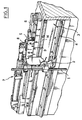
- - la figure 1 représente une vue en perspective d'un dispositif selon l'invention,
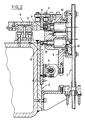
- - la figure 2 représente une vue en coupe transversale de ce dispositif.
- FIG. 1 represents a perspective view of a device according to the invention,
- - Figure 2 shows a cross-sectional view of this device.
Sur ces figures, l'invention est illustrée dans une application, non limitative, au déplacement d'injecteurs, ou tubes d'alimentation, de poudre, alignés rectilignement dans une buse, telle que décrite au préambule de la présente description, d'une première à une deuxième configuration en ligne, qui se distinguent par l'écartement relatif d'au moins une partie des injecteurs alignés.In these figures, the invention is illustrated in a nonlimiting application to the displacement of injectors, or supply tubes, of powder, aligned rectilinearly in a nozzle, as described in the preamble to the present description, of a first to a second in-line configuration, which are distinguished by the relative spacing of at least part of the aligned injectors.
A la figure 1, on a représenté un injecteur (1) constituant l'un des organes à déplacer pour passer d'une configuration à l'autre. Il est clair que le dispositif comprend en fait plusieurs injecteurs, un seul de ceux-ci étant représenté à la figure 1 pour La clarté de la présente description. L'injecteur (1) est monté sur un chariot (2) mobile sur un rail (4) fixé sur un banc (3) rectiligne. Le banc (3) est commun à un groupe de chariots qui portent, chacun, un des injecteurs (3). Une navette (5) est mobile sur une glissière (6) fixée sur le banc (3) et ses déplacements sont assurés par un organe moteur 7, tel qu'un vérin par exemple. La navette (5) comprend une plaque (8) située dans un plan parallèle à la course du chariot la plaque (8) de la navette (5) est munie d'une pluralité de Logements (9) en alignement parallèle à la direction de la course du chariot. Ces logements (9) font face au noyau (11 - fig 2) d'un électro-aimant (10 - fig. 2) monté sur le chariot (2). Le noyau (11 - fig 2) est mobile entre une position rétractée, qui correspond à un non-couplage avec la navette, et une position débordante permettant à l'extrémité du noyau de pénétrer dans un des Logements (9) de la plaque (8) de la navette en vue du déplacement transversal du chariot.In Figure 1, there is shown an injector (1) constituting one of the members to be moved to pass from a configuration to another. It is clear that the device in fact comprises several injectors, only one of these being shown in FIG. 1 for clarity of the present description. The injector (1) is mounted on a carriage (2) movable on a rail (4) fixed on a straight bench (3). The bench (3) is common to a group of carriages which each carry one of the injectors (3). A shuttle (5) is movable on a slide (6) fixed on the bench (3) and its movements are ensured by a
Le vérin (7) qui entraîne la navette en translation sur la glissière (6) peut être un vérin électrique commandé par un moteur pas à pas.The jack (7) which drives the shuttle in translation on the slide (6) can be an electric jack controlled by a stepping motor.
Avantageusement, le dispositif peut comprendre en outre des moyens de couplage à frottement entre le banc (3) et chacun des chariots (2) pour maintenir ce dernier dans une position fixe par rapport au banc (3) après son instaltion par la navette (5) dans une position prédéterminée. Ces moyens de couplage à frottement comprennent par exemple un deuxième électro-aimant (12 - fig 2) monté sur le chariot (2) et dont le noyau (13 - fig 2) est mobile entre une position rétractée, permettant le déplacement du chariot par la navette, et une position débordante dans laquelle il porte sur une plage rugueuse (14 - fig 1 et 2) du banc (3) pour assurer le couplage à frottement.Advantageously, the device may further comprise friction coupling means between the bench (3) and each of the carriages (2) to maintain the latter in a fixed position relative to the bench (3) after its installation by the shuttle (5 ) in a predetermined position. These friction coupling means comprise for example a second electromagnet (12 - fig 2) mounted on the carriage (2) and whose core (13 - fig 2) is movable between a retracted position, allowing the carriage to be moved by the shuttle, and an overflowing position in which it bears on a rough surface (14 - fig 1 and 2) of the bench (3) to ensure friction coupling.
Afin d'automatiser la reconfiguration des positions relatives des différents organes alignés, les moyens de couplage des chariots à la navette, les moyens de couplage à frottement des chariots au banc et le vérin (7) de déplacement de la navette, sont commandés par un ordinateur convenablement programmé.In order to automate the reconfiguration of the relative positions of the different aligned members, the means for coupling the carriages to the shuttle, the coupling means friction of the carriages on the bench and the actuator (7) for moving the shuttle, are controlled by a suitably programmed computer.
Ainsi, lors de la production, on prélève un échantillon de ruban de verre enduit, comme on l'a indiqué précédemment, en découpant une bande transversale relativement étroite dans ce ruban et on mesure la réflectance de cette bande sur toute sa longueur avec un appareil, tel un spotmètre à balayage.Thus, during production, a sample of coated glass ribbon is taken, as indicated above, by cutting a relatively narrow transverse strip in this ribbon and the reflectance of this strip is measured over its entire length with a device. , such as a scanning spotmeter.
Les mesures sont numérisées avec un convertisseur analogique - numérique et fournies à un ordinateur, tel qu'un ordinateur IBM-PC, chargé avec un logiciel d'exploitation de ces mesures pour en déduire d'éventuelles corrections de l'écartement des injecteurs, corrections qui sont commandées grâce à des signaux de commande appropriés au dispositif suivant l'invention pour réagencer les injecteurs suivant une deuxième configuration propre à faire disparaître les défauts d'uniformité détectés par le spotmètre.The measurements are digitized with an analog-to-digital converter and supplied to a computer, such as an IBM-PC computer, loaded with an operating software for these measurements to deduce any corrections to the spacing of the injectors, corrections which are controlled by means of control signals suitable for the device according to the invention for rearranging the injectors according to a second configuration capable of eliminating the uniformity defects detected by the spotmeter.
Les mesures de réflectance sont faites de préférence directement sur le ruban de verre en mouvement pour éviter l'arrêt de la production.The reflectance measurements are preferably made directly on the moving glass ribbon to avoid stopping production.
En fonctionnement, le dispositif selon l'invention, assure ainsi sur la commande de l'ordinateur, le déplacement de la navette (5) de manière à mettre l'un des logements (9) de la plaque (8) en vis-à-vis du noyau (11) de l'électro-aimant (10) qui sert au couplage du chariot (2) à la navette. L'ordinateur commande l'excitation de cet électro-aimant (10) de telle sorte que l'extrémité du noyau (11) de l'électro-aimant (10) pénètre dans le logement (9) qui lui fait face, ce qui a pour effet de rendre solidaire le chariot (2) et la navette (5). Le deuxième électro-aimant (12), servant de moyen de couplage à frottement entre le banc (3) et le chariot (2), est alors commandé de manière à rétracter son noyau (13) et désaccoupler le chariot (2) du banc (3). Le chariot (2) est alors uniquement couplé à la navette (5). L'ordinateur commande le déplacement de cette dernière, sous l'action du vérin (7) d'une distance déterminée. La navette est avantageusement dé placée par pas élémentaire, par exemple de 0,25 mm. Lorsque le chariot occupe la position souhaitée, l'ordinateur commande le deuxième l'électro-aimant (12) de manière que son noyau occupe une position débordante lui permettant de porter sur la plage rugueuse (14) du banc (3) pour assurer l'immobilisation du chariot (2) sur ce banc (3).In operation, the device according to the invention thus ensures, on the control of the computer, the movement of the shuttle (5) so as to bring one of the housings (9) of the plate (8) opposite. -screw of the core (11) of the electromagnet (10) which is used to couple the carriage (2) to the shuttle. The computer controls the excitation of this electromagnet (10) so that the end of the core (11) of the electromagnet (10) enters the housing (9) which faces it, which has the effect of making the carriage (2) and the shuttle (5) integral. The second electromagnet (12), serving as a friction coupling means between the bench (3) and the carriage (2), is then controlled so as to retract its core (13) and uncoupled the carriage (2) from the bench (3). The carriage (2) is then only coupled to the shuttle (5). The computer controls the movement of the latter, under the action of the jack (7) by a determined distance. The shuttle is advantageously placed in elementary steps, for example 0.25 mm. When the carriage occupies the desired position, the computer controls the second electromagnet (12) so that its core occupies an overhanging position allowing it to carry on the rough surface (14) of the bench (3) to ensure the immobilization of the carriage (2) on this bench (3).
L'électro-aimant (10) est alors commandé pour que son noyau (11) se rétracte et désaccouple le chariot (2) et la navette (5).The electromagnet (10) is then controlled so that its core (11) retracts and uncouples the carriage (2) and the shuttle (5).
La navette (5) est alors de nouveau déplacée de manière à mettre l'un des logements (9) de la plaque (8) face à un autre chariot à déplacer. Le processus précédent se répète pour modifier Les positions des différents chariots et les placer suivant la nouvelle configuration souhaitée.The shuttle (5) is then again moved so as to put one of the housings (9) of the plate (8) facing another carriage to be moved. The previous process is repeated to modify the positions of the different carriages and place them according to the new desired configuration.
Eventuellement, la navette (5) peut être couplée simultanément à plusieurs chariots coopérant alors chacun avec l'un des logements (9) prévus dans la plaque (8) pour être déplacés simultanément.Optionally, the shuttle (5) can be coupled simultaneously to several carriages then each cooperating with one of the housings (9) provided in the plate (8) to be moved simultaneously.
Le procédé et le dispositif selon l'invention, décrits précédemment, sont particulièrement appropriés pour modifier automatiquement les positions d'injecteurs utiles pour l'alimentation en produits pulvérulents d'une buse de distribution, telle que décrite dans les brevets cités précédemment, en vue de la projection de ces produits sur un substrat sous-jacent en défilement, tel qu'un ruban de verre pour y former une couche de propriétés particulières. L'invention permet en effet un réglage rapide, et à distance, des écarts entre les injecteurs dès que le défaut d'homogénéité de la couche, mentionné précédemment, a été détecté. La durée qui s'écoule entre le moment de la détection des défauts dans la couche et celui où la pulvérisation peut être reprise après le réglage des écarts des injecteurs peut être réduite à 30 mn par exemple. L'invention présente donc l'avantage notamment de rendre plus aisée les interventions sur la chaîne de fabrication, de réduire la durée de ces interventions ainsi que la perte de production.The method and the device according to the invention, described above, are particularly suitable for automatically modifying the positions of injectors useful for supplying pulverulent products to a dispensing nozzle, as described in the patents cited above, with a view to the projection of these products on an underlying moving substrate, such as a glass ribbon to form a layer of particular properties. The invention in fact allows rapid and remote adjustment of the differences between the injectors as soon as the layer homogeneity defect, mentioned above, has been detected. The time which elapses between the moment of detection of the defects in the layer and that when the spraying can be resumed after the adjustment of the injector gaps can be reduced to 30 min for example. The invention therefore has the advantage in particular of making interventions on the production line easier, of reducing the duration of these interventions as well as the loss of production.
Le procédé et le dispositif selon l'invention peuvent être utilisables évidemment dans tout système comprenant des organes alignés dont les positions relatives doivent être modifiées.The method and the device according to the invention can obviously be used in any system comprising aligned members whose relative positions must be changed.
Claims (13)
Priority Applications (1)
| Application Number | Priority Date | Filing Date | Title |
|---|---|---|---|
| AT90400943T ATE90605T1 (en) | 1989-04-12 | 1990-04-06 | METHOD OF MODIFYING THE RELATIVE POSITIONS OF A MULTIPLE ALIGNED ELEMENTS AND APPARATUS FOR CARRYING OUT THESE METHOD. |
Applications Claiming Priority (2)
| Application Number | Priority Date | Filing Date | Title |
|---|---|---|---|
| FR8904791 | 1989-04-12 | ||
| FR8904791A FR2645773B1 (en) | 1989-04-12 | 1989-04-12 | METHOD FOR MODIFYING THE POSITIONS RELATING TO A PLURALITY OF ALIGNED ORGANS AND DEVICE FOR CARRYING OUT SAID METHOD |
Publications (2)
| Publication Number | Publication Date |
|---|---|
| EP0392902A1 true EP0392902A1 (en) | 1990-10-17 |
| EP0392902B1 EP0392902B1 (en) | 1993-06-16 |
Family
ID=9380616
Family Applications (1)
| Application Number | Title | Priority Date | Filing Date |
|---|---|---|---|
| EP90400943A Expired - Lifetime EP0392902B1 (en) | 1989-04-12 | 1990-04-06 | Method of modifying the relative positions of a plurality of aligned parts, and device for performing this method |
Country Status (15)
| Country | Link |
|---|---|
| US (1) | US5105759A (en) |
| EP (1) | EP0392902B1 (en) |
| JP (1) | JPH02298376A (en) |
| KR (1) | KR0127673B1 (en) |
| AT (1) | ATE90605T1 (en) |
| AU (1) | AU626037B2 (en) |
| BR (1) | BR9001731A (en) |
| CA (1) | CA2014389A1 (en) |
| CZ (1) | CZ284070B6 (en) |
| DD (1) | DD297922A5 (en) |
| DE (1) | DE69001945T2 (en) |
| ES (1) | ES2043302T3 (en) |
| FR (1) | FR2645773B1 (en) |
| HU (1) | HU208264B (en) |
| MX (1) | MX172971B (en) |
Cited By (1)
| Publication number | Priority date | Publication date | Assignee | Title |
|---|---|---|---|---|
| EP0704249A1 (en) | 1994-09-27 | 1996-04-03 | Saint-Gobain Vitrage | Device for distributing pulverulent solids on the surface of a substrate for coating this substrate |
Families Citing this family (2)
| Publication number | Priority date | Publication date | Assignee | Title |
|---|---|---|---|---|
| KR100555532B1 (en) | 2003-11-27 | 2006-03-03 | 삼성전자주식회사 | Memory test circuit and test system |
| ITMI20041250A1 (en) * | 2004-06-22 | 2004-09-22 | Bavelloni Z Spa | LOADING AND CUTTING PROCEDURE OF GLASS SLABS ON CUTTING TABLES |
Citations (2)
| Publication number | Priority date | Publication date | Assignee | Title |
|---|---|---|---|---|
| DE2535973A1 (en) * | 1975-08-12 | 1977-02-17 | Siemens Ag | Multiple spindle gantry drill - has tool carrier at multiple of hole index distance above sliding worktable |
| EP0249742A1 (en) * | 1986-06-16 | 1987-12-23 | Emag Maschinenfabrik Gmbh | Central-driving engine |
Family Cites Families (6)
| Publication number | Priority date | Publication date | Assignee | Title |
|---|---|---|---|---|
| US3785474A (en) * | 1972-01-11 | 1974-01-15 | T Nakamoto | Apparatus for sorting and distributing clothing |
| FR2429635A1 (en) * | 1978-06-30 | 1980-01-25 | Ramo Sa | CLAMPING DEVICE FOR SIMULTANEOUS MACHINING OF THE TWO END OF A WORKPIECE |
| FR2575679B1 (en) * | 1985-01-07 | 1988-05-27 | Saint Gobain Vitrage | IMPROVEMENT IN THE PROCESS OF COATING A SUBSTRATE SUCH AS A GLASS TAPE, WITH A POWDERY PRODUCT, AND DEVICE FOR CARRYING OUT SAID METHOD |
| JPS6211570A (en) * | 1985-07-05 | 1987-01-20 | Honda Motor Co Ltd | Automatic coater |
| FR2626872B1 (en) * | 1988-02-09 | 1992-10-30 | Saint Gobain Vitrage | IMPROVED PROCESS AND DEVICE FOR COATING A SUBSTRATE, SUCH AS A GLASS TAPE WITH A POWDERY PRODUCT |
| US5007351A (en) * | 1989-02-03 | 1991-04-16 | Spacesaver Corporation | Mobile carriage with center drive |
-
1989
- 1989-04-12 FR FR8904791A patent/FR2645773B1/en not_active Expired - Fee Related
-
1990
- 1990-04-03 MX MX020157A patent/MX172971B/en unknown
- 1990-04-04 AU AU52579/90A patent/AU626037B2/en not_active Ceased
- 1990-04-06 AT AT90400943T patent/ATE90605T1/en not_active IP Right Cessation
- 1990-04-06 DE DE90400943T patent/DE69001945T2/en not_active Expired - Fee Related
- 1990-04-06 US US07/506,283 patent/US5105759A/en not_active Expired - Fee Related
- 1990-04-06 EP EP90400943A patent/EP0392902B1/en not_active Expired - Lifetime
- 1990-04-06 ES ES90400943T patent/ES2043302T3/en not_active Expired - Lifetime
- 1990-04-10 HU HU902141A patent/HU208264B/en not_active IP Right Cessation
- 1990-04-11 BR BR909001731A patent/BR9001731A/en not_active IP Right Cessation
- 1990-04-11 CA CA002014389A patent/CA2014389A1/en not_active Abandoned
- 1990-04-11 CZ CS901816A patent/CZ284070B6/en not_active IP Right Cessation
- 1990-04-11 KR KR1019900004998A patent/KR0127673B1/en not_active Expired - Fee Related
- 1990-04-12 DD DD90339702A patent/DD297922A5/en not_active IP Right Cessation
- 1990-04-12 JP JP2097097A patent/JPH02298376A/en active Pending
Patent Citations (2)
| Publication number | Priority date | Publication date | Assignee | Title |
|---|---|---|---|---|
| DE2535973A1 (en) * | 1975-08-12 | 1977-02-17 | Siemens Ag | Multiple spindle gantry drill - has tool carrier at multiple of hole index distance above sliding worktable |
| EP0249742A1 (en) * | 1986-06-16 | 1987-12-23 | Emag Maschinenfabrik Gmbh | Central-driving engine |
Cited By (1)
| Publication number | Priority date | Publication date | Assignee | Title |
|---|---|---|---|---|
| EP0704249A1 (en) | 1994-09-27 | 1996-04-03 | Saint-Gobain Vitrage | Device for distributing pulverulent solids on the surface of a substrate for coating this substrate |
Also Published As
| Publication number | Publication date |
|---|---|
| JPH02298376A (en) | 1990-12-10 |
| CS9001816A2 (en) | 1991-09-15 |
| CA2014389A1 (en) | 1990-10-12 |
| HU902141D0 (en) | 1990-07-28 |
| AU5257990A (en) | 1990-10-18 |
| KR0127673B1 (en) | 1997-12-30 |
| FR2645773A1 (en) | 1990-10-19 |
| BR9001731A (en) | 1991-06-04 |
| HU208264B (en) | 1993-09-28 |
| DE69001945D1 (en) | 1993-07-22 |
| DE69001945T2 (en) | 1993-12-16 |
| ES2043302T3 (en) | 1993-12-16 |
| EP0392902B1 (en) | 1993-06-16 |
| HUT55263A (en) | 1991-05-28 |
| CZ284070B6 (en) | 1998-08-12 |
| MX172971B (en) | 1994-01-26 |
| KR900015820A (en) | 1990-11-10 |
| DD297922A5 (en) | 1992-01-30 |
| ATE90605T1 (en) | 1993-07-15 |
| FR2645773B1 (en) | 1991-08-30 |
| US5105759A (en) | 1992-04-21 |
| AU626037B2 (en) | 1992-07-23 |
Similar Documents
| Publication | Publication Date | Title |
|---|---|---|
| EP0187094B2 (en) | Contactless eddy current testing method, and apparatus for carrying out this method | |
| KR19980087550A (en) | Method and apparatus for thickness control during chemical mechanical polishing | |
| LU88402A1 (en) | Thin film thickness control | |
| EP0501909B1 (en) | Device and process for applying adhesive to a web | |
| EP0392902B1 (en) | Method of modifying the relative positions of a plurality of aligned parts, and device for performing this method | |
| FR2474552A1 (en) | RADIATION CONTROL DEVICE AND METHOD FOR MATERIAL MANUFACTURING MACHINE USING BETA-RAY THICKNESS MEASURING APPARATUS | |
| EP1067360B1 (en) | Device for the estimation of the geometry of articles transported on a conveyor | |
| EP0200604B1 (en) | Cloth spreading apparatus | |
| EP1373613B1 (en) | System for automated management for spreading a textile cable web | |
| EP0553004B2 (en) | Device for measuring the reflection properties of a transparent substrate, especially glass, with a partially reflecting layer | |
| EP0704249B1 (en) | Device for distributing pulverulent solids on the surface of a substrate for coating this substrate | |
| CN121297686A (en) | A device and method for dynamic thickness measurement of ultrathin liquid films | |
| FR2664710A1 (en) | METHOD AND INSTALLATION FOR DEPOSITING ANTIREFLECTIVE LAYERS AND CONTROLLING THEIR THICKNESS. | |
| WO1995001855A1 (en) | Cutting machine using a rotary wheel for cutting a flexible material consisting of a single sheet or a small mat of sheets, and method for adjusting said machine | |
| KR102011426B1 (en) | Thin film coating apparatus for THz beam splitter and coating methode thereof | |
| FR2734178A1 (en) | METHOD AND APPARATUS FOR IMPROVING THE UNIFORMITY OF A LIQUID CURTAIN IN A CURTAIN COATING SYSTEM | |
| FR2627109A1 (en) | METHOD AND APPARATUS FOR CALIBRATION OF PATTERN PRODUCTION SYSTEM FOR THICK FILM CIRCUIT | |
| EP0476029A1 (en) | Method for cutting printed boards for examination of the plating result on the walls in holes arranged in the board. | |
| EP0186564A1 (en) | Process and apparatus for controlling and regulating the coating thickness of supports | |
| US20230213332A1 (en) | Apparatus for characterization of graphene oxide coatings | |
| FR2575955A1 (en) | Process and installation for grinding trueing and controlling the diameter of a grinding wheel | |
| EP4497571A1 (en) | Modular machine for additive manufacturing, subtraction or transformation of material | |
| FR3148730A1 (en) | APPARATUS FOR ADDITIVE MANUFACTURING OF A PART BY LASER FUSION ON A POWDER BED AND METHOD FOR CONTROLLING THE CHARACTERISTICS OF A PART DURING ITS ADDITIVE MANUFACTURING BY MEANS OF SUCH AN APPARATUS | |
| HK30129919A2 (en) | A method and system for data acquisition in online optical inspection for additive manufacturing | |
| FR2609805A1 (en) | Method and installation for checking the oiling of an electrically conducting fibre |
Legal Events
| Date | Code | Title | Description |
|---|---|---|---|
| PUAI | Public reference made under article 153(3) epc to a published international application that has entered the european phase |
Free format text: ORIGINAL CODE: 0009012 |
|
| AK | Designated contracting states |
Kind code of ref document: A1 Designated state(s): AT BE CH DE ES FR GB IT LI LU NL SE |
|
| 17P | Request for examination filed |
Effective date: 19901106 |
|
| 17Q | First examination report despatched |
Effective date: 19921021 |
|
| GRAA | (expected) grant |
Free format text: ORIGINAL CODE: 0009210 |
|
| AK | Designated contracting states |
Kind code of ref document: B1 Designated state(s): AT BE CH DE ES FR GB IT LI LU NL SE |
|
| REF | Corresponds to: |
Ref document number: 90605 Country of ref document: AT Date of ref document: 19930715 Kind code of ref document: T |
|
| REF | Corresponds to: |
Ref document number: 69001945 Country of ref document: DE Date of ref document: 19930722 |
|
| ITF | It: translation for a ep patent filed | ||
| GBT | Gb: translation of ep patent filed (gb section 77(6)(a)/1977) |
Effective date: 19931020 |
|
| REG | Reference to a national code |
Ref country code: ES Ref legal event code: FG2A Ref document number: 2043302 Country of ref document: ES Kind code of ref document: T3 |
|
| PLBE | No opposition filed within time limit |
Free format text: ORIGINAL CODE: 0009261 |
|
| STAA | Information on the status of an ep patent application or granted ep patent |
Free format text: STATUS: NO OPPOSITION FILED WITHIN TIME LIMIT |
|
| 26N | No opposition filed | ||
| EPTA | Lu: last paid annual fee | ||
| EAL | Se: european patent in force in sweden |
Ref document number: 90400943.8 |
|
| PGFP | Annual fee paid to national office [announced via postgrant information from national office to epo] |
Ref country code: AT Payment date: 19980410 Year of fee payment: 9 |
|
| PGFP | Annual fee paid to national office [announced via postgrant information from national office to epo] |
Ref country code: ES Payment date: 19980416 Year of fee payment: 9 |
|
| PGFP | Annual fee paid to national office [announced via postgrant information from national office to epo] |
Ref country code: NL Payment date: 19980430 Year of fee payment: 9 |
|
| PGFP | Annual fee paid to national office [announced via postgrant information from national office to epo] |
Ref country code: DE Payment date: 19980523 Year of fee payment: 9 |
|
| PGFP | Annual fee paid to national office [announced via postgrant information from national office to epo] |
Ref country code: CH Payment date: 19980721 Year of fee payment: 9 |
|
| PGFP | Annual fee paid to national office [announced via postgrant information from national office to epo] |
Ref country code: SE Payment date: 19990304 Year of fee payment: 10 |
|
| PGFP | Annual fee paid to national office [announced via postgrant information from national office to epo] |
Ref country code: GB Payment date: 19990305 Year of fee payment: 10 |
|
| PG25 | Lapsed in a contracting state [announced via postgrant information from national office to epo] |
Ref country code: AT Free format text: LAPSE BECAUSE OF NON-PAYMENT OF DUE FEES Effective date: 19990406 |
|
| PG25 | Lapsed in a contracting state [announced via postgrant information from national office to epo] |
Ref country code: ES Free format text: LAPSE BECAUSE OF NON-PAYMENT OF DUE FEES Effective date: 19990407 |
|
| PGFP | Annual fee paid to national office [announced via postgrant information from national office to epo] |
Ref country code: LU Payment date: 19990413 Year of fee payment: 10 |
|
| PGFP | Annual fee paid to national office [announced via postgrant information from national office to epo] |
Ref country code: FR Payment date: 19990415 Year of fee payment: 10 |
|
| PGFP | Annual fee paid to national office [announced via postgrant information from national office to epo] |
Ref country code: BE Payment date: 19990429 Year of fee payment: 10 |
|
| PG25 | Lapsed in a contracting state [announced via postgrant information from national office to epo] |
Ref country code: LI Free format text: LAPSE BECAUSE OF NON-PAYMENT OF DUE FEES Effective date: 19990430 Ref country code: CH Free format text: LAPSE BECAUSE OF NON-PAYMENT OF DUE FEES Effective date: 19990430 |
|
| PG25 | Lapsed in a contracting state [announced via postgrant information from national office to epo] |
Ref country code: NL Free format text: LAPSE BECAUSE OF NON-PAYMENT OF DUE FEES Effective date: 19991101 |
|
| REG | Reference to a national code |
Ref country code: CH Ref legal event code: PL |
|
| NLV4 | Nl: lapsed or anulled due to non-payment of the annual fee |
Effective date: 19991101 |
|
| PG25 | Lapsed in a contracting state [announced via postgrant information from national office to epo] |
Ref country code: DE Free format text: LAPSE BECAUSE OF NON-PAYMENT OF DUE FEES Effective date: 20000201 |
|
| PG25 | Lapsed in a contracting state [announced via postgrant information from national office to epo] |
Ref country code: LU Free format text: LAPSE BECAUSE OF NON-PAYMENT OF DUE FEES Effective date: 20000406 Ref country code: GB Free format text: LAPSE BECAUSE OF NON-PAYMENT OF DUE FEES Effective date: 20000406 |
|
| PG25 | Lapsed in a contracting state [announced via postgrant information from national office to epo] |
Ref country code: SE Free format text: LAPSE BECAUSE OF NON-PAYMENT OF DUE FEES Effective date: 20000407 |
|
| PG25 | Lapsed in a contracting state [announced via postgrant information from national office to epo] |
Ref country code: BE Free format text: LAPSE BECAUSE OF NON-PAYMENT OF DUE FEES Effective date: 20000430 |
|
| BERE | Be: lapsed |
Owner name: SAINT-GOBAIN VITRAGE INTERNATIONAL Effective date: 20000430 |
|
| GBPC | Gb: european patent ceased through non-payment of renewal fee |
Effective date: 20000406 |
|
| EUG | Se: european patent has lapsed |
Ref document number: 90400943.8 |
|
| PG25 | Lapsed in a contracting state [announced via postgrant information from national office to epo] |
Ref country code: FR Free format text: LAPSE BECAUSE OF NON-PAYMENT OF DUE FEES Effective date: 20001229 |
|
| REG | Reference to a national code |
Ref country code: FR Ref legal event code: ST |
|
| REG | Reference to a national code |
Ref country code: ES Ref legal event code: FD2A Effective date: 20010503 |
|
| PG25 | Lapsed in a contracting state [announced via postgrant information from national office to epo] |
Ref country code: IT Free format text: LAPSE BECAUSE OF NON-PAYMENT OF DUE FEES;WARNING: LAPSES OF ITALIAN PATENTS WITH EFFECTIVE DATE BEFORE 2007 MAY HAVE OCCURRED AT ANY TIME BEFORE 2007. THE CORRECT EFFECTIVE DATE MAY BE DIFFERENT FROM THE ONE RECORDED. Effective date: 20050406 |