EP0392908A1 - Kupplung für Leitungen - Google Patents
Kupplung für Leitungen Download PDFInfo
- Publication number
- EP0392908A1 EP0392908A1 EP90400952A EP90400952A EP0392908A1 EP 0392908 A1 EP0392908 A1 EP 0392908A1 EP 90400952 A EP90400952 A EP 90400952A EP 90400952 A EP90400952 A EP 90400952A EP 0392908 A1 EP0392908 A1 EP 0392908A1
- Authority
- EP
- European Patent Office
- Prior art keywords
- piping
- locking
- tabs
- connection
- tubing
- Prior art date
- Legal status (The legal status is an assumption and is not a legal conclusion. Google has not performed a legal analysis and makes no representation as to the accuracy of the status listed.)
- Withdrawn
Links
- 229920002994 synthetic fiber Polymers 0.000 claims abstract description 4
- 238000012423 maintenance Methods 0.000 claims description 6
- 238000000465 moulding Methods 0.000 claims description 4
- 239000004033 plastic Substances 0.000 claims description 3
- 229920003002 synthetic resin Polymers 0.000 claims 1
- 239000000057 synthetic resin Substances 0.000 claims 1
- 210000000078 claw Anatomy 0.000 abstract 3
- 230000000903 blocking effect Effects 0.000 description 5
- 239000000446 fuel Substances 0.000 description 3
- XLYOFNOQVPJJNP-UHFFFAOYSA-N water Substances O XLYOFNOQVPJJNP-UHFFFAOYSA-N 0.000 description 3
- 238000007789 sealing Methods 0.000 description 2
- 210000002105 tongue Anatomy 0.000 description 2
- 208000031968 Cadaver Diseases 0.000 description 1
- 239000004959 Rilsan Substances 0.000 description 1
- 230000008878 coupling Effects 0.000 description 1
- 238000010168 coupling process Methods 0.000 description 1
- 238000005859 coupling reaction Methods 0.000 description 1
- 230000008014 freezing Effects 0.000 description 1
- 238000007710 freezing Methods 0.000 description 1
- 239000002828 fuel tank Substances 0.000 description 1
- 238000002347 injection Methods 0.000 description 1
- 239000007924 injection Substances 0.000 description 1
- 239000000463 material Substances 0.000 description 1
- 239000011347 resin Substances 0.000 description 1
- 229920005989 resin Polymers 0.000 description 1
Images

Classifications
-
- F—MECHANICAL ENGINEERING; LIGHTING; HEATING; WEAPONS; BLASTING
- F16—ENGINEERING ELEMENTS AND UNITS; GENERAL MEASURES FOR PRODUCING AND MAINTAINING EFFECTIVE FUNCTIONING OF MACHINES OR INSTALLATIONS; THERMAL INSULATION IN GENERAL
- F16L—PIPES; JOINTS OR FITTINGS FOR PIPES; SUPPORTS FOR PIPES, CABLES OR PROTECTIVE TUBING; MEANS FOR THERMAL INSULATION IN GENERAL
- F16L37/00—Couplings of the quick-acting type
- F16L37/08—Couplings of the quick-acting type in which the connection between abutting or axially overlapping ends is maintained by locking members
- F16L37/12—Couplings of the quick-acting type in which the connection between abutting or axially overlapping ends is maintained by locking members using hooks, pawls, or other movable or insertable locking members
Definitions
- the present invention relates to a connection system for smooth pipes and tubes intended more particularly for the automotive industry.
- connection systems must meet a certain number of imperative requirements, among which we can cite: - very high reliability to avoid any cause of failure resulting from the defectiveness of such fittings; - a great aptitude for rapid assembly and disassembly so as to facilitate maintenance operations; - Excellent sealing, in particular both with water and with air, so as to avoid, on the one hand, any introduction of air into the pipes thus connected, this introduction of air resulting in a power failure of the engine when the pipes are those of the fuel supply circuit and on the other hand any introduction of water into the pipes which is a cause of freezing at low temperatures which also results in a fuel supply failure of the motor ; - a low cost price.
- connection systems sold in particular for the applications mentioned above and which are made of synthetic material, in particular "Rilsan”.
- Rubberan synthetic material
- the subject of the present invention is a fitting for piping, in particular for the automobile industry, characterized in that it consists of a body of synthetic material extended by means ensuring the connection either on a pipe or directly on a reservoir or the like and provided with an axial bore provided with a portion of tubing forming a male connecting element for the piping to be connected and on which said piping engages, in that said portion of tubing has a lower part whose outer surface is frustoconical to ensure the maintenance of said piping whose end abuts on the bottom of said bore and in that said bore axial opens on each side of said body according to two lateral windows in which are positioned legs articulated on said body and designed so as to block said piping after its connection to said portion of tubing, said locking tabs coming from molding with said body, so as to obtain a one-piece connection.
- the locking tabs are articulated on the body by means of thin tabs forming hinges, molded with the whole of the connector.
- These locking tabs have recesses in the form of cylindrical cradles which are applied against the facing surfaces of the piping to be connected when the tabs are positioned in the respective windows provided for this purpose in the body of the fitting, the tabs being in further provided with locking means which cooperate with corresponding means provided on the body of the connector.
- the locking means provided on the locking tabs are produced in the form of a clipping system, the corresponding elements of which are respectively provided at the end of each locking part and on the body.
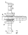
- the connector according to the present invention essentially comprises a body 10 having substantially the shape of an elliptical cylinder and which is extended by means 12 ensuring the connection on a pipe (not shown in the drawing) .
- This set is made of a plastic material, in particular a systhetic resin for example in "Rislan".
- the body is provided with an axial bore 16 which comprises a portion of tubing 14 which, as will be seen below, constitutes a male connecting element for the smooth pipe 18 to be connected to the pipe mounted on the fitting by means 12.
- This axial bore 16 opens on each side of the body (FIG. 1) by means of two side windows 20, 20 ′.
- the portion of tubing 14 on which the smooth piping 18 engages for its connection has a lower part 14 ′ whose outer surface is of frustoconical shape. As will be seen below, this profile of the portion of tubing 14 ensures the maintenance of the piping 18 on the connection system as well as the sealing.
- the body 10 is moreover provided with two tabs 22, 22 ′, which are designed and produced so as to block the piping 18 after its connection to the portion of tubing 14, these blocking tabs which come from molding with the body 10 coming to be positioned in the side windows 20, 20 ′ as will be described below.
- each locking tab such as 22, 22 ′ is articulated on the body 10 using a thin tongue forming a hinge 26, 26 ′ respectively, these hinges coming from molding with the whole fitting.
- Each locking tab is provided with a recess which in this embodiment has the form of a cylindrical cradle 28, 28 ′ respectively and which is intended to come to bear against the corresponding surface of the piping 18 to be connected, when the locking tabs 22, 22 ′ are positioned in their respective windows 20, 20 ′.
- said locking tabs are provided with locking means which are designed so as to cooperate with corresponding means provided on the body of the connector 10.
- the locking means are produced in the form of a clipping system, the corresponding elements of which are provided on the one hand at the end of each locking tab 22, 22 ′ (elements 30, 30 ′) and on the other hand on the body 10 (elements 32, 32 ′).
- the fitting system described above is implemented as follows: - The user sets up the connector body 10 on the pipe to be connected by introducing the end 12 of the connector body into the internal bore of this pipe, or by directly fixing the connector, for example on a tank, the end 12 in fir tail of the embodiment illustrated by the drawings then being replaced by a threaded tail which is connected directly to the tank. Then, it introduces the piping 18 to be connected into the axial bore 16 of the body 10 in the space between the tubing portion 14 and the internal cylindrical surface of this bore. The piping 18 is therefore introduced onto the portion of tubing forming a male connecting element 14 by applying against the external surface of this element 14.
- the frustoconical shape of the lower part 14 ′ of this portion of tubing 14 makes it possible to obtain a blocking of the piping 18 in the body of the fitting, when the piping 18 is forced into the tubing portion 14 until the end of the pipe 18 abuts against the bottom 24 of the 'axial bore 16; - After this establishment of the piping 18 on the body of the connector, the user folds each locking tab 22, 22 ′ towards the body 10 by pivoting around the tongues 26, 26 ′ forming grooves.
- each locking tab is positioned in the corresponding side window 20, 20 ′ provided in the body 10 of the connector, its recess in the form of a cylindrical cradle 28, 28 ′ coming to bear against the opposite surfaces of the piping 18 and, finally, the clipping system 30, 30′-32, 32 ′ ensures the locking of the locking tabs 22, 22 ′ in their housing of the body 10, which completes the blocking of the piping 18 in the fitting .
- connection system makes it possible to produce a one-piece connection, very easy to handle and to implement and ensuring rapid connection, efficient, reliable and watertight of the two smooth pipes to be connected, or of a pipe and a tank, or the like in the case specified above where the connector is directly mounted by screwing on such a tank or equivalent.
- the piping 18 is held on the body 10 by its blocking on the portion of tubing 14 in the bore 16 of the body 10, its end abutting the bottom 24 of this axial bore, which ensures the tightness of the connection both screw -with respect to air than with respect to water, the tabs 22, 22 ′ also make it possible to obtain the maintenance of this seal by blocking any relative movement of the piping 18 relative to the body 10 of the fitting.
- the connector is easily removable which facilitates maintenance operations, since the locking tabs 22, 22 ′ can be unlocked from the body 10, the piping 18 then being detached from the connector by traction.
Landscapes
- Engineering & Computer Science (AREA)
- General Engineering & Computer Science (AREA)
- Mechanical Engineering (AREA)
- Quick-Acting Or Multi-Walled Pipe Joints (AREA)
Applications Claiming Priority (2)
| Application Number | Priority Date | Filing Date | Title |
|---|---|---|---|
| FR8904922 | 1989-04-13 | ||
| FR8904922A FR2645942B1 (fr) | 1989-04-13 | 1989-04-13 | Raccord pour tuyauterie |
Publications (1)
| Publication Number | Publication Date |
|---|---|
| EP0392908A1 true EP0392908A1 (de) | 1990-10-17 |
Family
ID=9380709
Family Applications (1)
| Application Number | Title | Priority Date | Filing Date |
|---|---|---|---|
| EP90400952A Withdrawn EP0392908A1 (de) | 1989-04-13 | 1990-04-06 | Kupplung für Leitungen |
Country Status (2)
| Country | Link |
|---|---|
| EP (1) | EP0392908A1 (de) |
| FR (1) | FR2645942B1 (de) |
Cited By (2)
| Publication number | Priority date | Publication date | Assignee | Title |
|---|---|---|---|---|
| US6672628B2 (en) | 2002-02-20 | 2004-01-06 | Masco Corporation Of Indiana | Quick connect hose coupling |
| DE10229004A1 (de) * | 2002-06-28 | 2004-01-29 | Veritas Ag | Leitungseinrichtung |
Citations (4)
| Publication number | Priority date | Publication date | Assignee | Title |
|---|---|---|---|---|
| EP0073892A1 (de) * | 1981-09-07 | 1983-03-16 | Alfred Grossauer | Anschlussnippel für umfangsgerippte Isolierrohre |
| EP0086900A1 (de) * | 1982-02-05 | 1983-08-31 | Agro Ag | Anschlussnippel aus Kunststoff für umfangsgerippte Isolierrohre |
| FR2528533A1 (fr) * | 1982-06-09 | 1983-12-16 | Capri Codec Sa | Raccord traversant a ecrou tournant pour gaine exterieurement spiralee |
| US4795197A (en) * | 1987-06-29 | 1989-01-03 | Deere & Company | Coupling for seed and fertilizer hoses |
-
1989
- 1989-04-13 FR FR8904922A patent/FR2645942B1/fr not_active Expired - Lifetime
-
1990
- 1990-04-06 EP EP90400952A patent/EP0392908A1/de not_active Withdrawn
Patent Citations (4)
| Publication number | Priority date | Publication date | Assignee | Title |
|---|---|---|---|---|
| EP0073892A1 (de) * | 1981-09-07 | 1983-03-16 | Alfred Grossauer | Anschlussnippel für umfangsgerippte Isolierrohre |
| EP0086900A1 (de) * | 1982-02-05 | 1983-08-31 | Agro Ag | Anschlussnippel aus Kunststoff für umfangsgerippte Isolierrohre |
| FR2528533A1 (fr) * | 1982-06-09 | 1983-12-16 | Capri Codec Sa | Raccord traversant a ecrou tournant pour gaine exterieurement spiralee |
| US4795197A (en) * | 1987-06-29 | 1989-01-03 | Deere & Company | Coupling for seed and fertilizer hoses |
Cited By (3)
| Publication number | Priority date | Publication date | Assignee | Title |
|---|---|---|---|---|
| US6672628B2 (en) | 2002-02-20 | 2004-01-06 | Masco Corporation Of Indiana | Quick connect hose coupling |
| DE10229004A1 (de) * | 2002-06-28 | 2004-01-29 | Veritas Ag | Leitungseinrichtung |
| DE10229004B4 (de) * | 2002-06-28 | 2005-09-29 | Veritas Ag | Leitungseinrichtung |
Also Published As
| Publication number | Publication date |
|---|---|
| FR2645942A1 (fr) | 1990-10-19 |
| FR2645942B1 (fr) | 1991-07-12 |
Similar Documents
| Publication | Publication Date | Title |
|---|---|---|
| EP1064489B1 (de) | Steck-kupplung für rohre | |
| EP1497582B1 (de) | Undurchlässige verbindungsvorrichtung, insbesondere für das motorlufteinlasssystem eines kraftfahrzeugs | |
| EP1248028B1 (de) | Abgedichtete Kupplung | |
| FR2829554A1 (fr) | Raccord encliquetable monocorps | |
| FR2713305A1 (fr) | Dispositif de raccord rapide pour tubulures d'échangeur de chaleur. | |
| FR2578364A1 (fr) | Connecteur electrique etanche | |
| FR2829219A1 (fr) | Raccord d'etancheite pre-assemble | |
| CA2797517A1 (fr) | Organe de verrouillage d'un dispositif de raccordement pour transfert de fluide, ce dispositif et son procede de verrouillage | |
| EP0327440A1 (de) | Verbindung zwischen einem Wärmeaustauscher und einem Rohrende | |
| FR2749639A1 (fr) | Dispositif de raccord rapide pour conduit de fluide sous pression | |
| FR2810087A1 (fr) | Element pourvu exterieurement de moyens pour cooperer avec un taraudage | |
| FR2795156A1 (fr) | Raccord encliquetable pour conduit de fluide, en particulier pour un circuit d'alimentation en carburant du moteur d'un vehicule automobile | |
| FR2646697A1 (fr) | Dispositif d'assemblage par encliquetage pour echangeurs de chaleur de vehicules automobiles | |
| EP0571286A1 (de) | Vorrichtung zum schnellen Verbinden von entweder einem rohrförmigen Element mit einem Rohrende oder einem System von rohrförmigen Elementen mit Rohrenden | |
| EP0392908A1 (de) | Kupplung für Leitungen | |
| EP1075619B1 (de) | Dichtung und rohrverbindung mit einer solchen vorrichtung | |
| FR2790535A1 (fr) | Attache perfectionnee pour la fixation de tubes ou analogues | |
| EP1605195B1 (de) | Rohrkupplungssystem und dazu gehöriges Montageverfahren | |
| EP0546911B1 (de) | Dichtungsring und Brennstofftank | |
| FR2962187A1 (fr) | Dispositif et procede de raccordement en particulier pour circuit de refroidissement d'eau de vehicule automobile. | |
| WO2008047002A2 (fr) | Dispositif de raccordement rotatif | |
| FR2867830A1 (fr) | Raccord verrouillable/deverrouillable de tuyauterie | |
| EP2402144B1 (de) | Anschlussvorrichtung und -verfahren, insbesondere für Wasserkühlkreislauf in einem Kraftfahrzeug | |
| FR2867829A1 (fr) | Raccord etanche entre une gaine annelee et un embout | |
| FR3039315B1 (fr) | Boitier pour fusible ameliore |
Legal Events
| Date | Code | Title | Description |
|---|---|---|---|
| PUAI | Public reference made under article 153(3) epc to a published international application that has entered the european phase |
Free format text: ORIGINAL CODE: 0009012 |
|
| AK | Designated contracting states |
Kind code of ref document: A1 Designated state(s): DE ES IT |
|
| STAA | Information on the status of an ep patent application or granted ep patent |
Free format text: STATUS: THE APPLICATION IS DEEMED TO BE WITHDRAWN |
|
| 18D | Application deemed to be withdrawn |
Effective date: 19910418 |