EP0393318A2 - Ensemble des éléments de construction pour une structure ou un échafaudage avec barres et raccords pour leur jonction - Google Patents
Ensemble des éléments de construction pour une structure ou un échafaudage avec barres et raccords pour leur jonction Download PDFInfo
- Publication number
- EP0393318A2 EP0393318A2 EP90102559A EP90102559A EP0393318A2 EP 0393318 A2 EP0393318 A2 EP 0393318A2 EP 90102559 A EP90102559 A EP 90102559A EP 90102559 A EP90102559 A EP 90102559A EP 0393318 A2 EP0393318 A2 EP 0393318A2
- Authority
- EP
- European Patent Office
- Prior art keywords
- coupling
- kit according
- projection
- retaining pins
- recess
- Prior art date
- Legal status (The legal status is an assumption and is not a legal conclusion. Google has not performed a legal analysis and makes no representation as to the accuracy of the status listed.)
- Granted
Links
Images




Classifications
-
- E—FIXED CONSTRUCTIONS
- E04—BUILDING
- E04B—GENERAL BUILDING CONSTRUCTIONS; WALLS, e.g. PARTITIONS; ROOFS; FLOORS; CEILINGS; INSULATION OR OTHER PROTECTION OF BUILDINGS
- E04B1/00—Constructions in general; Structures which are not restricted either to walls, e.g. partitions, or floors or ceilings or roofs
- E04B1/18—Structures comprising elongated load-supporting parts, e.g. columns, girders, skeletons
- E04B1/19—Three-dimensional [3D] framework structures
- E04B1/1903—Connecting nodes specially adapted therefor
- E04B1/1906—Connecting nodes specially adapted therefor with central spherical, semispherical or polyhedral connecting element
-
- E—FIXED CONSTRUCTIONS
- E04—BUILDING
- E04B—GENERAL BUILDING CONSTRUCTIONS; WALLS, e.g. PARTITIONS; ROOFS; FLOORS; CEILINGS; INSULATION OR OTHER PROTECTION OF BUILDINGS
- E04B1/00—Constructions in general; Structures which are not restricted either to walls, e.g. partitions, or floors or ceilings or roofs
- E04B1/18—Structures comprising elongated load-supporting parts, e.g. columns, girders, skeletons
- E04B1/19—Three-dimensional [3D] framework structures
- E04B1/1903—Connecting nodes specially adapted therefor
- E04B1/1909—Connecting nodes specially adapted therefor with central cylindrical connecting element
-
- E—FIXED CONSTRUCTIONS
- E04—BUILDING
- E04B—GENERAL BUILDING CONSTRUCTIONS; WALLS, e.g. PARTITIONS; ROOFS; FLOORS; CEILINGS; INSULATION OR OTHER PROTECTION OF BUILDINGS
- E04B1/00—Constructions in general; Structures which are not restricted either to walls, e.g. partitions, or floors or ceilings or roofs
- E04B1/18—Structures comprising elongated load-supporting parts, e.g. columns, girders, skeletons
- E04B1/19—Three-dimensional [3D] framework structures
- E04B2001/1924—Struts specially adapted therefor
- E04B2001/1927—Struts specially adapted therefor of essentially circular cross section
-
- E—FIXED CONSTRUCTIONS
- E04—BUILDING
- E04B—GENERAL BUILDING CONSTRUCTIONS; WALLS, e.g. PARTITIONS; ROOFS; FLOORS; CEILINGS; INSULATION OR OTHER PROTECTION OF BUILDINGS
- E04B1/00—Constructions in general; Structures which are not restricted either to walls, e.g. partitions, or floors or ceilings or roofs
- E04B1/18—Structures comprising elongated load-supporting parts, e.g. columns, girders, skeletons
- E04B1/19—Three-dimensional [3D] framework structures
- E04B2001/1957—Details of connections between nodes and struts
- E04B2001/196—Screw connections with axis parallel to the main axis of the strut
-
- E—FIXED CONSTRUCTIONS
- E04—BUILDING
- E04B—GENERAL BUILDING CONSTRUCTIONS; WALLS, e.g. PARTITIONS; ROOFS; FLOORS; CEILINGS; INSULATION OR OTHER PROTECTION OF BUILDINGS
- E04B1/00—Constructions in general; Structures which are not restricted either to walls, e.g. partitions, or floors or ceilings or roofs
- E04B1/18—Structures comprising elongated load-supporting parts, e.g. columns, girders, skeletons
- E04B1/19—Three-dimensional [3D] framework structures
- E04B2001/1957—Details of connections between nodes and struts
- E04B2001/1966—Formlocking connections other than screw connections
-
- E—FIXED CONSTRUCTIONS
- E04—BUILDING
- E04B—GENERAL BUILDING CONSTRUCTIONS; WALLS, e.g. PARTITIONS; ROOFS; FLOORS; CEILINGS; INSULATION OR OTHER PROTECTION OF BUILDINGS
- E04B1/00—Constructions in general; Structures which are not restricted either to walls, e.g. partitions, or floors or ceilings or roofs
- E04B1/18—Structures comprising elongated load-supporting parts, e.g. columns, girders, skeletons
- E04B1/19—Three-dimensional [3D] framework structures
- E04B2001/1975—Frameworks where the struts are directly connected to each other, i.e. without interposed connecting nodes or plates
-
- E—FIXED CONSTRUCTIONS
- E04—BUILDING
- E04B—GENERAL BUILDING CONSTRUCTIONS; WALLS, e.g. PARTITIONS; ROOFS; FLOORS; CEILINGS; INSULATION OR OTHER PROTECTION OF BUILDINGS
- E04B1/00—Constructions in general; Structures which are not restricted either to walls, e.g. partitions, or floors or ceilings or roofs
- E04B1/18—Structures comprising elongated load-supporting parts, e.g. columns, girders, skeletons
- E04B1/19—Three-dimensional [3D] framework structures
- E04B2001/1981—Three-dimensional [3D] framework structures characterised by the grid type of the outer planes of the framework
- E04B2001/1984—Three-dimensional [3D] framework structures characterised by the grid type of the outer planes of the framework rectangular, e.g. square, grid
-
- Y—GENERAL TAGGING OF NEW TECHNOLOGICAL DEVELOPMENTS; GENERAL TAGGING OF CROSS-SECTIONAL TECHNOLOGIES SPANNING OVER SEVERAL SECTIONS OF THE IPC; TECHNICAL SUBJECTS COVERED BY FORMER USPC CROSS-REFERENCE ART COLLECTIONS [XRACs] AND DIGESTS
- Y10—TECHNICAL SUBJECTS COVERED BY FORMER USPC
- Y10T—TECHNICAL SUBJECTS COVERED BY FORMER US CLASSIFICATION
- Y10T403/00—Joints and connections
- Y10T403/34—Branched
- Y10T403/341—Three or more radiating members
- Y10T403/342—Polyhedral
-
- Y—GENERAL TAGGING OF NEW TECHNOLOGICAL DEVELOPMENTS; GENERAL TAGGING OF CROSS-SECTIONAL TECHNOLOGIES SPANNING OVER SEVERAL SECTIONS OF THE IPC; TECHNICAL SUBJECTS COVERED BY FORMER USPC CROSS-REFERENCE ART COLLECTIONS [XRACs] AND DIGESTS
- Y10—TECHNICAL SUBJECTS COVERED BY FORMER USPC
- Y10T—TECHNICAL SUBJECTS COVERED BY FORMER US CLASSIFICATION
- Y10T403/00—Joints and connections
- Y10T403/34—Branched
- Y10T403/347—Polyhedral
-
- Y—GENERAL TAGGING OF NEW TECHNOLOGICAL DEVELOPMENTS; GENERAL TAGGING OF CROSS-SECTIONAL TECHNOLOGIES SPANNING OVER SEVERAL SECTIONS OF THE IPC; TECHNICAL SUBJECTS COVERED BY FORMER USPC CROSS-REFERENCE ART COLLECTIONS [XRACs] AND DIGESTS
- Y10—TECHNICAL SUBJECTS COVERED BY FORMER USPC
- Y10T—TECHNICAL SUBJECTS COVERED BY FORMER US CLASSIFICATION
- Y10T403/00—Joints and connections
- Y10T403/70—Interfitted members
- Y10T403/7005—Lugged member, rotary engagement
Definitions
- the invention relates to a kit for a structure or scaffolding, in particular a truss structure, with struts, beams, supports or the like. Bars and with couplings for connecting at least two or more bars at corners, nodes or the like. Connection points of the supporting structure, coupling openings and coupling projections being releasably connectable to one another.
- Spherical couplings are provided, which have a plurality of radially inwardly directed threaded holes as coupling openings. Threaded pieces protrude on the end faces of the rods, the threads of which fit into the threaded holes of the spherical coupling parts. By rotating these threaded parts relative to the bars, they can be screwed into these threads and thereby axially pushed out of the bars.
- hexagonal sleeves are provided in a complex manner on the outside of the threaded projections, within which the threaded parts are mounted, these being rotatably connected to the sleeves, so that the rotation of the sleeve also causes entrainment of the screw part in the direction of rotation.
- an axial guide between the sleeve and the threaded part is provided at the same time, in this way the threaded pieces are screwed into the screw holes of the ball couplings. Appropriate storage and mounting of the threaded pieces in the end areas of the rods is required.
- the overall result is a relatively complex construction, in which, in particular, the assembly of a space frame with a large number of connection points and coupling parts is very time-consuming, since numerous screw connections have to be made. Disassembly is correspondingly time-consuming. This time requirement is particularly unfavorable when it comes to supporting structures that are only required for a relatively short time, for example for the design of exhibition stands, and that have to be assembled and dismantled accordingly often.
- hammer head screws are provided at the front ends of the rods, the threads of which engage in a nut rotatably mounted on the end face of the rod.
- the hammer-head-shaped end can be introduced into the coupling part in one orientation direction through an elongated hole coupling opening and anchored after rotation by 90 °. Then, by turning the nut mentioned, this hammer head screw is tightened relative to a sleeve located between the end face of the rod and the surface of the coupling part.
- the inclined surfaces can thereby simplify the compression of the latching elements, but a corresponding force-consuming compression by the user is required during disassembly.
- the compression-preventing locks In order to avoid unwanted loosening, the compression-preventing locks must be inserted in the coupling area, the removal of which is also time-consuming.
- a correspondingly long slot is required at the end of the rod, which not only weakens this rod, but also results in an unsightly picture overall.
- this type of coupling practically does not eliminate any play required within the coupling parts for their actuation, so that the overall construction does not permit the desirable rigidity.
- kits There are also a number of other examples of such kits known, which are based more or less on a comparable principle and an extensive effort by experts to obtain a support structure with coupling points for the individual rods that can be set up safely.
- the invention has for its object to provide a kit with rods and coupling of the type mentioned, in which the connection of the rods with the coupling part and the release can be carried out more quickly, but the forces occurring can still be transmitted well. At the same time, slitting of the rod ends should be avoided.
- the coupling projection in the one position in which the recess and the retaining pin fit together can be inserted and automatically locked by the springing back of the retaining pin, while it is simply rotated by about 90 ° to disengage, whereby the coupling pin by the not recessed area of the coupling projection is in turn deflected, after which the coupling projection can be withdrawn again without any problems.
- Coupling and uncoupling can therefore be carried out very quickly and easily. Due to the axially adjustable threaded or sliding sleeve, the respective coupling position can be fixed and a clearance important for assembly can be eliminated.
- Screwing movements for fixing the coupling and for switching off its play for the actual coupling connection are of no importance, so that only relatively few rotations or even less than one rotation on the sleeve or a short sliding path can suffice. It is particularly expedient if two, preferably parallel, holding pins are provided in the coupling opening, if the coupling projection has a rounding, tapering or the like at its front end in the insertion direction. has, which can be inserted between the two retaining pins if or the like following the sharpening.
- the axial dimension of the lateral recess of the coupling projection can be greater than the thickness of the retaining pin or pins and the adjustment path of the clamping, threaded sleeve or sliding sleeve can correspond to at least this difference in the dimension of the recess compared to that of the retaining pin or be greater.
- This axially larger extension of the recess results in the desired axial play of the rod with respect to the coupling, so that such a rod can also be inserted with its two coupling ends between two coupling points and coupling parts.
- the corresponding axial play can then be due to the corresponding sliding or Screw path of the clamping or threaded sleeve can be eliminated in the position of use.
- This form fit between the recess and the retaining pin can be designed particularly inexpensively and yet effectively if the retaining pin or pins have a round cross section and the limitation of the coupling recess facing the insertion tip of the coupling projection from the outside or top of the coupling projection to the recess base - forming the undercut - runs obliquely at an acute angle to the recess base and is preferably rounded at the transition to the recess base, in particular with a radius of curvature which corresponds to the radius of the cross section of the retaining pin.
- the retaining pin comes to rest under the tensile load of the clamping or threaded sleeve at this transition between the bottom of the recess and the lateral boundary of the coupling recess and is fixed there by the oblique course of the recess boundary.
- the additional coupling part cooperating with the bars can be provided with an approximately spherical, ring-shaped, cross-shaped, angular, T-shaped or the like. Outside contour can be provided and the coupling counterpart interacting therewith can be arranged on the end faces of the rods.
- a reverse arrangement would also be conceivable, in which the coupling opening with the retaining pins on the end faces of the rods and the coupling projections are provided on the coupling part, but this would result in a complex coupling part and possibly in the event that not all coupling points of this coupling part are required , the need for disassembly of the coupling projections.
- the part having the coupling projection or the part containing the retaining pins could be rotated when disengaging, in order to deflect the retaining pins out of the recesses and then to be able to pull the coupling parts apart.
- the cheaper and optically cheaper solution is that the coupling opening (s) containing the retaining pins are arranged on the coupling part and the coupling projection on the end face of the rods.
- Embodiments of the invention and in particular the coupling and thereby both the arrangement of the clamping or screw sleeve as well as that of the holding brackets and also the resilient and deflectable mounting of the holding rods are the subject of claims 8 to 22.
- Claim 23 relates to a solution in which the coupling projections are provided on the surface of the coupling part and the coupling openings on the end faces of the rods, but the design of the coupling opening and the coupling projections corresponds to those of the reverse arrangement and thus the type of assembly and disassembly remains the same.
- Claim 24 contains alternatives to the screw or threaded sleeve.
- FIG. 16 An assembly designated as a whole with 1, in FIG. 1 to form a space structure, in FIG. 16 to a support structure has struts, beams, supports or the like. on, which are referred to below as rods 2.
- rods 2 struts, beams, supports or the like. on, which are referred to below as rods 2.
- vertical supports 3 are also provided and the kit 1 assembled into a scaffold.
- the kit also includes couplings to be described in more detail for connecting at least two or more rods 2 at corners, nodes or the like. Connection points of the supporting structure, coupling openings 4 and coupling projections 5 being releasably connectable to one another.
- the respective coupling is designed in such a way that within the clear cross-section of the respective coupling opening 4, at least one, in all exemplary embodiments two holding pins 6 which can be deflected or deflected laterally against a restoring force are provided so that the coupling projection 5 which fits into the coupling opening 4 is one when inserting the retaining pin 6, the inclined surface 7 and following this inclined surface 7 has a radially receding recess 8 compared to the largest cross section of the coupling projection 5, into which the retaining pin 6 springs back after a correspondingly deep insertion of the coupling projection 5 into the coupling opening 4, which position 4 can be seen particularly well.
- an area 9 is provided on the coupling projection 5, which, when the coupling projection 5 is rotated relative, i.e. either an actual rotation of the coupling projection 5 or of the part having the coupling opening 4, radially extends the retaining pin 6 to the outer dimension of the Coupling projection 5 deflects, because this area 9 has the outer dimension of the coupling projection 5.
- a threaded portion 10 is provided, on which one in the longitudinal direction of the Rod 2 and the coupling projection 5 is arranged by screwing adjustable threaded sleeve 11, but which is not used to produce a screw connection as a coupling, but rather in the coupling position, that is, when the coupling projection 5 is connected within the coupling opening 4 with the retaining pin 6, against that of the coupling connection adjacent surface area in the Sensed screwed and countered is that the coupling projection 5 and its recess 8 is braced against the retaining pin 6 against the direction of insertion.
- two parallel holding pins 6 are provided in the coupling opening 4, each leaving a space between them.
- the coupling projection 5 has at its front end in the insertion direction as the already mentioned inclined surface 7 a rounding or tapering or according to FIG. 4 a combination of both, which can be inserted between the two retaining pins 6 of each coupling opening 5.
- two mutually opposite, radially recessed recesses 8 are provided on the coupling projection 5 for snapping in the two retaining pins 6 and in the circumferential direction between the two recesses 8 in each case regions 9, the radial extent of which is the lateral adjustability and adjustment of the retaining pins 6 and the greatest radial extent of the coupling projection 5 in the area of its insertion end.
- This symmetrical arrangement of the holding pins 6 and the matching recesses 8 on a coupling projection can be seen, for example, in FIG. 3.
- the dimensional relationships and diameter relationships of the areas 9 in the circumferential direction next to the recesses 8 can be seen, for example, in FIG.
- the axial dimension of the lateral recesses 8 is gem. 4 greater than the thickness of the holding pins 5 and the adjustment path of the clamping threaded sleeves 11 corresponds at least to this difference in the dimension of the recess 8 compared to that of the holding pin 6 or is expediently somewhat larger in order to achieve a very secure bracing. Since the coupling openings 4 are deeper than the length of the coupling protrusions 5, these can also be inserted deeper into the coupling openings 4 in accordance with the larger dimension of the recess 8, which is helpful if, after coupling one end of a rod 2, the opposite End to be inserted into a coupling part 12 already held on rods 2.
- the retaining pins themselves are essentially rigid and resiliently mounted for their deflection against their deflection direction, for which there are various possibilities according to the description below.
- the recess 8 on the coupling projection 5, at its tip 7 closer to its tip 7, may have or form an undercut which overlaps the retaining pin 6 according to FIG. 4 somewhat, at least after the bracing and not just tangent to this retaining pin.
- the retaining pins 6 have a circular cross section and the boundary 8a of the coupling recess 8 facing the insertion tip 7 of the coupling projection 5 extends obliquely from the outside or top of the coupling projection 5 to the recess base 8b at an acute angle.
- the transition 13 to the recess base 8b is rounded approximately with the radius of curvature which corresponds to the radius of the cross section of the retaining pin 6, so that it fits well into this undercut and rounding of the transition 13.
- Fig. 4 illustrates that thereby the recess 8 engages over the holding pin 6 in the use position hook-like, so that even at peak loads an unwanted deflection of the holding pin 6 is avoided.
- an additional coupling part 12 cooperating with the rods 6 is provided, which in the exemplary embodiments according to FIGS. 1 to 15 is provided with an approximately spherical outer contour, while in the exemplary embodiment according to FIGS. 16 to 19 a coupling part 12 with an annular contour is provided.
- cruciform, angular or T-shaped outer contours would also be possible, the coupling counterpart interacting with this coupling part 12 in each case being arranged on the end face of the rods 2.
- the coupling openings 4 in the coupling part 12 and the coupling projections are arranged on the end faces of the rods 2.
- the coupling part 12 it would also be possible for the coupling part 12 to have coupling projections 5 protruding on its surface with bevels 7 or tips and recesses 8 arranged behind them in the axial direction and insertion direction, which e.g. could be releasably attachable to this coupling part 12, so that coupling projections 5 are only arranged where a rod 2 is really to be attached, and that the coupling opening and the holding pins 6 located in the opening 5 are provided in the end face of the rods 6.
- the coupling parts 12 have the coupling openings 4 and the rods 2 have the coupling projections 5.
- the threaded sleeve 11 which is adjustable in the axial direction of the rod 2, is arranged on this threaded piece and axially beyond its end against the coupling part 12 by screwing adjustable. This results in that in the coupling position, when the threaded sleeve 11 abuts the coupling part 12 and prevents unwanted disengagement, between the coupling tion part 12 facing away from the threaded sleeve 11 and the rod 2, a gap or space 14 is present, which is closed again when the threaded sleeve 11 is loosened.
- this gap 14 corresponds to the already mentioned adjustment path of the clamping threaded sleeve 11, which corresponds at least to the extent by which the recess 8 is larger in the axial direction than the diameter of the retaining pin 6.
- the edge region of the coupling opening 4 that is to say the surface region of the coupling part 12 which extends to a certain extent around the mouth of this opening 4, is designed to be rotationally symmetrical with respect to the central axis of the coupling opening 4 or the screw sleeve 11 and corresponds approximately to the likewise rotationally symmetrical shape of the end face of the screw sleeve which is adjustable against it 11 match, so that it can be rotated easily and without tilting against the surface area of the coupling part 12 and a rotation is still allowed when there is already frictional contact. Furthermore, the clamping forces are distributed well and symmetrically around the coupling opening 4 in this way.
- this edge region of the perforation 4 may have the shape of a positive spherical section or a spherical zone and the end face of the screw sleeve 11 may have a matching negative spherical section.
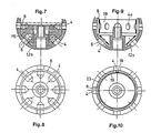
- This coupling part 12 in the exemplary embodiments according to FIGS. 2 to 15 is approximately spherical and is composed of at least two releasable shells 12a and 12b and the spring element or elements, namely either the already described rubber body 15 or other solutions to be described below, take this Bowls detachable in themselves. If the shells 12a and 12b are separated, the rubber body 15 can be removed for repair purposes, for example. It can be clearly seen that the two shells have in their interior perpendicular to their parting line, one of which has a threaded hole into which a screw 16 can be inserted from the other side. In FIG. 2 it is also indicated that the rubber body 15 can also be divided into two halves, in which case the openings in the area of the parting plane must be provided with retaining pins 6 which are held on at least one of these halves by a plug connection.
- rubber bodies 15 are again provided, however, the retaining pins are connected to rings that run parallel to the parting plane, i.e. the retaining pins 6 of a plurality of coupling openings 4 are connected to one another in one piece, so that the retaining pins 6 then continue in each case between the coupling openings 4 acted upon by them.
- the rings arranged within the coupling part 12 according to FIGS. 7 and 8 each have a pin-shaped cross section and are arranged behind the coupling openings 4 in their clear cross section and can be pressed apart against restoring forces, for example that of a rubber body.
- spreading springs 17 are arranged between two adjacent coupling openings 4 on the coupling part 12 in the interior thereof, which act on the holding pins 6 arranged on the mutually facing edges of the coupling openings 4.
- 11 and 12 show an arrangement in which the spreading springs 17 arranged between mutually adjacent holding pins 6, adjacent coupling openings 4, are approximately U-shaped or V-shaped and with their connecting end 17a on a middle support, in this case the one for the other Screwing the half-shells of the coupling part 12 serving socket inside the housing of the coupling part les 12 are supported.
- three retaining pins arranged approximately transversely to the parting plane of the coupling part 12 are integrally connected to one another and form a type of bracket which can be seen particularly well in FIG. 11. This makes it possible to resiliently mount three pairs of retaining pins 6 with a single spreading spring 17 located approximately in the parting plane.
- FIGS. 11 and 12 show that on the inside of the coupling opening 4 in the space between two retaining pins 6 belonging to this coupling opening 4, a rib-shaped spacer 18 for the retaining pins 6, for example a support rib or the like. is provided on the inside of the housing, which serve as an abutment against the spring elements acting on the retaining pins 6 against their deflection direction. This can also be provided in the embodiment according to FIGS. 11 and 12. This allows the spreading springs 17 acting on the retaining pins to be given a certain pretension.
- Fig. 13 to 15 it can be provided that on the inside of the coupling part 12 in the insertion direction behind the holding pins 6, this is provided from the back against the coupling openings 4 supporting ring 19, which at the same time spreading springs 20 to form the restoring force for the individual holding pins 6 wears.
- the support ring 19 has openings 21, in which the central regions 22 of the approximately W-shaped or M-shaped spreading springs are held in the manner shown in FIG. 14.
- This solution has the advantage that the spreading springs 20 are not supported by the central connecting sleeves of the two shells of the coupling part 12, but are supported in a defined form by the support ring 19 and this additionally sets the retaining pins against the inside of the coupling part 12.
- Such a support ring 19 also shows the embodiment of FIGS. 9 and 10, wherein instead of the spreading springs 20 in this case rubber plates 23 are inserted between the adjacent holding pins, so that in this case a combination of the solution with a rubber body 15 and the Solution with a support ring 19 is realized.
- the support rings 19 of course also have the coupling opening 4 continuing holes 4a.
- rubber bodies 15 are again provided in the interior of the annular coupling part, in which, according to FIG. 17, retaining pins 6 held transversely to the circumference of this annular coupling part 12 or, according to FIG. 19, two rings that run parallel to the circumference and connect all retaining pins 6 in each case can be embedded.
- couplings are provided which have coupling openings 4 and coupling projections 5 in the usual way, so that the coupling process and also the release of the coupling can be carried out as simply and quickly as possible, and yet a safe and firm coupling can be achieved are provided within the respective coupling opening 4 within its clear cross-section laterally deflectable retaining pins 6 against a restoring force.
- the coupling projection 5 which fits into the coupling opening 4 has an inclined surface 7 or tip which acts on these retaining pins 6 when pushed in and moves apart and then has a recess 8 which radially recedes from the largest cross section of the coupling projection 5 and into which the retaining pins 6 are again can spring back, whereby the first loose clutch is already accomplished.
- regions 9 are provided which, when the coupling projection 5 is rotated relatively, in turn deflect the retaining pins 6 radially up to the outer dimension of the coupling projection 5, so that the coupling projection 5 is easily pulled out of the opening 4 or vice versa the opening 4 can be pulled off the projection 5 very easily.
- a sliding or screw sleeve 11 is also provided in the area of the coupling projection 5, which can be adjusted and countered in the coupling position against the surface area adjacent to the coupling connection, as a result of which the coupling projection 5 and above all the radial boundary 8a of its recess 8 is clamped against the retaining pin 6 against the direction of insertion.
- an intermediate disk 24 preferably made of plastic, can be provided as a rotation lock and surface protection.
- a sliding sleeve that could be axially adjustable relative to the rod 2 could be provided in another way, which can be inserted with the rod 2 through a plug-in wedge that penetrates both parts or a rotatable eccentric or the like could be slidably connected in the longitudinal direction.
Landscapes
- Engineering & Computer Science (AREA)
- Architecture (AREA)
- Physics & Mathematics (AREA)
- Electromagnetism (AREA)
- Civil Engineering (AREA)
- Structural Engineering (AREA)
- Mutual Connection Of Rods And Tubes (AREA)
- Joining Of Building Structures In Genera (AREA)
- Hooks, Suction Cups, And Attachment By Adhesive Means (AREA)
- Ladders (AREA)
- Connection Of Plates (AREA)
- Orthopedics, Nursing, And Contraception (AREA)
- Connector Housings Or Holding Contact Members (AREA)
Priority Applications (1)
| Application Number | Priority Date | Filing Date | Title |
|---|---|---|---|
| AT90102559T ATE80433T1 (de) | 1989-03-29 | 1990-02-09 | Bausatz fuer ein tragwerk oder geruest mit staeben und kupplungen zu deren verbindung. |
Applications Claiming Priority (2)
| Application Number | Priority Date | Filing Date | Title |
|---|---|---|---|
| DE3910106A DE3910106A1 (de) | 1989-03-29 | 1989-03-29 | Bausatz fuer ein tragwerk oder geruest mit staeben und kupplungen zu deren verbinden |
| DE3910106 | 1989-03-29 |
Publications (3)
| Publication Number | Publication Date |
|---|---|
| EP0393318A2 true EP0393318A2 (fr) | 1990-10-24 |
| EP0393318A3 EP0393318A3 (fr) | 1991-07-17 |
| EP0393318B1 EP0393318B1 (fr) | 1992-09-09 |
Family
ID=6377356
Family Applications (1)
| Application Number | Title | Priority Date | Filing Date |
|---|---|---|---|
| EP90102559A Expired - Lifetime EP0393318B1 (fr) | 1989-03-29 | 1990-02-09 | Ensemble des éléments de construction pour une structure ou un échafaudage avec barres et raccords pour leur jonction |
Country Status (9)
| Country | Link |
|---|---|
| US (1) | US5074700A (fr) |
| EP (1) | EP0393318B1 (fr) |
| JP (1) | JP2865786B2 (fr) |
| AT (1) | ATE80433T1 (fr) |
| AU (1) | AU628147B2 (fr) |
| BR (1) | BR9001413A (fr) |
| CA (1) | CA2013200C (fr) |
| DD (1) | DD299079A5 (fr) |
| DE (2) | DE3910106A1 (fr) |
Cited By (1)
| Publication number | Priority date | Publication date | Assignee | Title |
|---|---|---|---|---|
| ITBO20120242A1 (it) * | 2012-05-03 | 2013-11-04 | Silentbreeze Yurt Di Gianluca Beggi O | Giunto nodale per strutture reticolari, particolarmente per cupole geodesiche |
Families Citing this family (20)
| Publication number | Priority date | Publication date | Assignee | Title |
|---|---|---|---|---|
| DE4217826A1 (de) * | 1992-05-29 | 1993-12-02 | Prime Line Werbe Und Displayba | Verbindungselement |
| US5421666A (en) * | 1993-09-24 | 1995-06-06 | Spears; Donald L. | Pipe connector for framework fabrication |
| DE19800979A1 (de) * | 1998-01-14 | 1999-07-22 | Burkhardt Leitner | Verbindungsknoten |
| US6475117B1 (en) * | 1998-07-15 | 2002-11-05 | Landscape Structures, Inc. | Connection/Structure |
| SE515230C2 (sv) * | 1998-10-15 | 2001-07-02 | Bertil Olsson | Ramanordning och förfarande för framställning av en dylik |
| ES2156695B1 (es) * | 1999-01-21 | 2002-05-01 | Esturen S A | Bancada para distribucion de cargas. |
| US6378265B1 (en) * | 1999-03-01 | 2002-04-30 | Matias Konstandt | Space frame construction assembly |
| FR2813928B1 (fr) * | 2000-09-12 | 2003-09-26 | Alm | Assemblage de deux pieces dont l'une est fixe et l'autre amovible, utilisable par exemple pour l'equipement d'une table chirurgicale |
| US6471168B1 (en) * | 2001-08-16 | 2002-10-29 | Chun-Hsien Tseng | Modular table leg assembly |
| US7364487B2 (en) | 2004-10-15 | 2008-04-29 | Cranium, Inc. | Structure building toy |
| US20080016789A1 (en) * | 2006-07-18 | 2008-01-24 | Boots Alfred H | Spherical hub for modular structure system |
| US20090093182A1 (en) * | 2007-10-05 | 2009-04-09 | Cranium, Inc. | Structure building toy |
| US7896016B2 (en) * | 2008-10-17 | 2011-03-01 | Golden Season Pte Ltd | Hub assembly |
| GR1008008B (el) * | 2011-12-16 | 2013-10-04 | Σπυριδων Αναστασιου Μαστρογιαννης | Συστημα κατασκευης βασεων στηριξης φωτοβολταϊκων στοιχειων με ειδικο πολυσυνδεσμο κατασκευης τριγωνικων στοιχειων |
| US20130244530A1 (en) * | 2012-03-19 | 2013-09-19 | John Renfro | Foam construction toy |
| AU2016222269B2 (en) * | 2015-02-16 | 2021-09-09 | Rhino Play Pty. Ltd. | A modular playground apparatus |
| CN110578370B (zh) * | 2018-06-09 | 2020-11-03 | 青岛大方新瑞网络科技有限公司 | 一种钢结构连接用螺栓球 |
| CN110984378B (zh) * | 2019-12-18 | 2021-02-19 | 浙江吉祥建设集团有限公司 | 一种节能环保的多功能层叠式建筑钢构件 |
| WO2022058855A1 (fr) * | 2020-09-16 | 2022-03-24 | Verster Abraham Marthinus | Kit de construction |
| US11918930B2 (en) * | 2021-10-15 | 2024-03-05 | Jam'n Products, Inc. | Connecting structure for toy tent |
Family Cites Families (12)
| Publication number | Priority date | Publication date | Assignee | Title |
|---|---|---|---|---|
| DE369790C (de) * | 1923-02-23 | Carl Weber | Loesbarer zweiteiliger Knopf | |
| US1595053A (en) * | 1925-06-15 | 1926-08-03 | Ballou & Co B A | Separable cuff button |
| GB576458A (en) * | 1944-09-01 | 1946-04-04 | Smith & Sons Ltd S | Improvements in or relating to devices for securing separable members in a detachable manner |
| GB1308298A (en) * | 1969-03-18 | 1973-02-21 | Hoy Co Ltd Austin | Tool-retaining means |
| DE2426973C3 (de) * | 1974-06-04 | 1980-08-14 | Armin 5970 Plettenberg Mylaeus | Knotenpunktverbindung für aus Rohrstäben gebildete Raumfachwerke |
| US3997989A (en) * | 1974-10-02 | 1976-12-21 | Caterpillar Tractor Co. | Tip retaining means with rotative locking tendencies |
| US3982841A (en) * | 1975-12-08 | 1976-09-28 | Abraham Endzweig | Connecting apparatus for frame members |
| US4129975A (en) * | 1977-03-09 | 1978-12-19 | Matrix Toys, Inc. | Construction set having clip fasteners |
| DE2822548C2 (de) * | 1978-05-23 | 1982-11-18 | Sandvik AB, 81181 Sandviken | Werkzeug, insbesondere Bergbaumeißel, mit einem Halteschaft zur Befestigung in einem Aufnahmeteil einer Maschine |
| US4580665A (en) * | 1979-05-18 | 1986-04-08 | Rockwell International Corporation | Quick connect brake coupling |
| DE3409916A1 (de) * | 1984-03-17 | 1985-09-26 | Rolf D. 3167 Burgdorf Jachmann | Knotenpunktverbindung fuer loesbar miteinander verbindbare zylinderfoermige staebe |
| DE3841305A1 (de) * | 1988-12-08 | 1990-06-13 | Iparterv Ipari Epuelettervezoe | Stabkonstruktion, insbesondere ebene oder raeumliche fachwerk-traegerkonstruktion |
-
1989
- 1989-03-29 DE DE3910106A patent/DE3910106A1/de active Granted
-
1990
- 1990-02-09 EP EP90102559A patent/EP0393318B1/fr not_active Expired - Lifetime
- 1990-02-09 DE DE9090102559T patent/DE59000291D1/de not_active Expired - Lifetime
- 1990-02-09 AT AT90102559T patent/ATE80433T1/de not_active IP Right Cessation
- 1990-03-22 US US07/497,448 patent/US5074700A/en not_active Expired - Lifetime
- 1990-03-26 AU AU52223/90A patent/AU628147B2/en not_active Ceased
- 1990-03-27 DD DD90339102A patent/DD299079A5/de unknown
- 1990-03-28 BR BR909001413A patent/BR9001413A/pt unknown
- 1990-03-28 CA CA002013200A patent/CA2013200C/fr not_active Expired - Fee Related
- 1990-03-29 JP JP2079034A patent/JP2865786B2/ja not_active Expired - Fee Related
Cited By (1)
| Publication number | Priority date | Publication date | Assignee | Title |
|---|---|---|---|---|
| ITBO20120242A1 (it) * | 2012-05-03 | 2013-11-04 | Silentbreeze Yurt Di Gianluca Beggi O | Giunto nodale per strutture reticolari, particolarmente per cupole geodesiche |
Also Published As
| Publication number | Publication date |
|---|---|
| ATE80433T1 (de) | 1992-09-15 |
| DE3910106A1 (de) | 1990-10-25 |
| CA2013200C (fr) | 1999-02-23 |
| AU628147B2 (en) | 1992-09-10 |
| AU5222390A (en) | 1990-10-04 |
| EP0393318B1 (fr) | 1992-09-09 |
| DD299079A5 (de) | 1992-03-26 |
| EP0393318A3 (fr) | 1991-07-17 |
| DE3910106C2 (fr) | 1993-05-27 |
| DE59000291D1 (de) | 1992-10-15 |
| BR9001413A (pt) | 1991-04-09 |
| JPH0355333A (ja) | 1991-03-11 |
| US5074700A (en) | 1991-12-24 |
| JP2865786B2 (ja) | 1999-03-08 |
| CA2013200A1 (fr) | 1990-09-29 |
Similar Documents
| Publication | Publication Date | Title |
|---|---|---|
| EP0393318B1 (fr) | Ensemble des éléments de construction pour une structure ou un échafaudage avec barres et raccords pour leur jonction | |
| EP1115955B1 (fr) | Element destine a la liaison de deux parties d'une cloison de separation, et utilisation dudit element | |
| EP0277319B1 (fr) | Elément de construction pour ensemble de construction | |
| DE2348239A1 (de) | Gestellanordnung | |
| DE1750969B1 (de) | Verbindungsvorrichtung zur verbindung rohrfoermiger teile | |
| EP0191426B1 (fr) | Treillis tridimensionnel | |
| EP0144030A2 (fr) | Tuyau profilé pour la réalisation de contructions facilement montables et démontables | |
| EP0333772B1 (fr) | Systeme modulaire de construction | |
| DE202015009438U1 (de) | Eckverbinder für stabförmige Profilelemente | |
| DE3142283C2 (de) | Bausatz zur Herstellung von Gestellen für den Möbelbau | |
| DE3231461A1 (de) | Verbindungsmuffe zum loesbaren befestigen des endes eines ersten stabes an einem zweiten stab | |
| DE102015013229A1 (de) | Pfosten-Träger-Verbindung und Verfahren zu deren Herstellung | |
| DE3443588C2 (de) | Anordnung zur Kreuzverbindung mindestens zweier Profile mit einem Knotenkörper | |
| DE8906283U1 (de) | Verbindungsbeschlag für Stabelemente | |
| DE2832087A1 (de) | Verbindung von hohlprofilen, insbesondere zum aufbau von regalen, geruesten u.dgl. | |
| DE3878175T2 (de) | Verbindungsteil. | |
| DE102007014263B3 (de) | Verbindungsknoten für ein zwei- oder dreimensionales Tragwerk | |
| DE102007014484B4 (de) | Vorrichtung zum lösbaren Verbinden | |
| DE2427242A1 (de) | Verbindungselement fuer hohlprofile | |
| DE202011002161U1 (de) | Tragwerksystem | |
| DE29603402U1 (de) | Rahmenwerk mit Winkel- oder Eckverbindungen von Metallprofilen, insbesondere aus Leichtmetall | |
| DE2131497C3 (de) | Anordnung zur Verbindung von mindestens zwei rohrförmigen Profilstäben miteinander | |
| AT346023B (de) | Vierkantprofilstange sowie verbindungselement zum loesbaren verbinden solcher stangen | |
| DE2612141A1 (de) | Verbindungs-beschlag | |
| DE10051323B4 (de) | Abschleppstange |
Legal Events
| Date | Code | Title | Description |
|---|---|---|---|
| PUAI | Public reference made under article 153(3) epc to a published international application that has entered the european phase |
Free format text: ORIGINAL CODE: 0009012 |
|
| AK | Designated contracting states |
Kind code of ref document: A2 Designated state(s): AT BE CH DE DK ES FR GB GR IT LI NL SE |
|
| PUAL | Search report despatched |
Free format text: ORIGINAL CODE: 0009013 |
|
| AK | Designated contracting states |
Kind code of ref document: A3 Designated state(s): AT BE CH DE DK ES FR GB GR IT LI NL SE |
|
| 17P | Request for examination filed |
Effective date: 19910627 |
|
| 17Q | First examination report despatched |
Effective date: 19911127 |
|
| GRAA | (expected) grant |
Free format text: ORIGINAL CODE: 0009210 |
|
| AK | Designated contracting states |
Kind code of ref document: B1 Designated state(s): AT BE CH DE DK ES FR GB GR IT LI NL SE |
|
| PG25 | Lapsed in a contracting state [announced via postgrant information from national office to epo] |
Ref country code: NL Effective date: 19920909 Ref country code: GR Free format text: LAPSE BECAUSE OF FAILURE TO SUBMIT A TRANSLATION OF THE DESCRIPTION OR TO PAY THE FEE WITHIN THE PRESCRIBED TIME-LIMIT Effective date: 19920909 Ref country code: ES Free format text: THE PATENT HAS BEEN ANNULLED BY A DECISION OF A NATIONAL AUTHORITY Effective date: 19920909 Ref country code: DK Effective date: 19920909 Ref country code: BE Effective date: 19920909 |
|
| REF | Corresponds to: |
Ref document number: 80433 Country of ref document: AT Date of ref document: 19920915 Kind code of ref document: T |
|
| REF | Corresponds to: |
Ref document number: 59000291 Country of ref document: DE Date of ref document: 19921015 |
|
| ITF | It: translation for a ep patent filed | ||
| GBT | Gb: translation of ep patent filed (gb section 77(6)(a)/1977) | ||
| ET | Fr: translation filed | ||
| NLV1 | Nl: lapsed or annulled due to failure to fulfill the requirements of art. 29p and 29m of the patents act | ||
| PLBE | No opposition filed within time limit |
Free format text: ORIGINAL CODE: 0009261 |
|
| STAA | Information on the status of an ep patent application or granted ep patent |
Free format text: STATUS: NO OPPOSITION FILED WITHIN TIME LIMIT |
|
| 26N | No opposition filed | ||
| EAL | Se: european patent in force in sweden |
Ref document number: 90102559.3 |
|
| REG | Reference to a national code |
Ref country code: GB Ref legal event code: IF02 |
|
| PGFP | Annual fee paid to national office [announced via postgrant information from national office to epo] |
Ref country code: FR Payment date: 20030211 Year of fee payment: 14 |
|
| PGFP | Annual fee paid to national office [announced via postgrant information from national office to epo] |
Ref country code: GB Payment date: 20030212 Year of fee payment: 14 |
|
| PGFP | Annual fee paid to national office [announced via postgrant information from national office to epo] |
Ref country code: SE Payment date: 20030213 Year of fee payment: 14 |
|
| PGFP | Annual fee paid to national office [announced via postgrant information from national office to epo] |
Ref country code: CH Payment date: 20030217 Year of fee payment: 14 |
|
| PGFP | Annual fee paid to national office [announced via postgrant information from national office to epo] |
Ref country code: DE Payment date: 20030221 Year of fee payment: 14 |
|
| PGFP | Annual fee paid to national office [announced via postgrant information from national office to epo] |
Ref country code: AT Payment date: 20030227 Year of fee payment: 14 |
|
| PG25 | Lapsed in a contracting state [announced via postgrant information from national office to epo] |
Ref country code: GB Free format text: LAPSE BECAUSE OF NON-PAYMENT OF DUE FEES Effective date: 20040209 Ref country code: AT Free format text: LAPSE BECAUSE OF NON-PAYMENT OF DUE FEES Effective date: 20040209 |
|
| PG25 | Lapsed in a contracting state [announced via postgrant information from national office to epo] |
Ref country code: SE Free format text: LAPSE BECAUSE OF NON-PAYMENT OF DUE FEES Effective date: 20040210 |
|
| PG25 | Lapsed in a contracting state [announced via postgrant information from national office to epo] |
Ref country code: LI Free format text: LAPSE BECAUSE OF NON-PAYMENT OF DUE FEES Effective date: 20040229 Ref country code: CH Free format text: LAPSE BECAUSE OF NON-PAYMENT OF DUE FEES Effective date: 20040229 |
|
| PG25 | Lapsed in a contracting state [announced via postgrant information from national office to epo] |
Ref country code: DE Free format text: LAPSE BECAUSE OF NON-PAYMENT OF DUE FEES Effective date: 20040901 |
|
| EUG | Se: european patent has lapsed | ||
| GBPC | Gb: european patent ceased through non-payment of renewal fee |
Effective date: 20040209 |
|
| REG | Reference to a national code |
Ref country code: CH Ref legal event code: PL |
|
| PG25 | Lapsed in a contracting state [announced via postgrant information from national office to epo] |
Ref country code: FR Free format text: LAPSE BECAUSE OF NON-PAYMENT OF DUE FEES Effective date: 20041029 |
|
| REG | Reference to a national code |
Ref country code: FR Ref legal event code: ST |
|
| PG25 | Lapsed in a contracting state [announced via postgrant information from national office to epo] |
Ref country code: IT Free format text: LAPSE BECAUSE OF NON-PAYMENT OF DUE FEES;WARNING: LAPSES OF ITALIAN PATENTS WITH EFFECTIVE DATE BEFORE 2007 MAY HAVE OCCURRED AT ANY TIME BEFORE 2007. THE CORRECT EFFECTIVE DATE MAY BE DIFFERENT FROM THE ONE RECORDED. Effective date: 20050209 |