EP0393365A2 - Procédé et dispositif d'alimentation en liquide de mouillage d'une machine à imprimer en offset - Google Patents
Procédé et dispositif d'alimentation en liquide de mouillage d'une machine à imprimer en offset Download PDFInfo
- Publication number
- EP0393365A2 EP0393365A2 EP90105186A EP90105186A EP0393365A2 EP 0393365 A2 EP0393365 A2 EP 0393365A2 EP 90105186 A EP90105186 A EP 90105186A EP 90105186 A EP90105186 A EP 90105186A EP 0393365 A2 EP0393365 A2 EP 0393365A2
- Authority
- EP
- European Patent Office
- Prior art keywords
- dampening solution
- dampening
- printing plate
- particular according
- toning
- Prior art date
- Legal status (The legal status is an assumption and is not a legal conclusion. Google has not performed a legal analysis and makes no representation as to the accuracy of the status listed.)
- Granted
Links
- 238000000034 method Methods 0.000 title claims abstract description 87
- 238000007645 offset printing Methods 0.000 title claims abstract description 38
- 239000007788 liquid Substances 0.000 title description 2
- 238000013016 damping Methods 0.000 title 1
- 238000007639 printing Methods 0.000 claims abstract description 97
- 230000008569 process Effects 0.000 claims abstract description 50
- 238000004519 manufacturing process Methods 0.000 claims abstract description 16
- 230000001419 dependent effect Effects 0.000 claims abstract description 10
- 238000007654 immersion Methods 0.000 claims description 15
- 238000007598 dipping method Methods 0.000 claims description 10
- 238000009826 distribution Methods 0.000 claims description 8
- 230000003287 optical effect Effects 0.000 claims description 6
- 238000004040 coloring Methods 0.000 claims description 5
- 238000001514 detection method Methods 0.000 claims description 3
- 230000002093 peripheral effect Effects 0.000 claims description 3
- 230000009467 reduction Effects 0.000 claims description 3
- 238000012544 monitoring process Methods 0.000 claims description 2
- 230000035807 sensation Effects 0.000 claims description 2
- 238000011144 upstream manufacturing Methods 0.000 claims description 2
- 230000006870 function Effects 0.000 description 5
- 238000011161 development Methods 0.000 description 4
- 230000018109 developmental process Effects 0.000 description 4
- 230000015572 biosynthetic process Effects 0.000 description 2
- 238000010586 diagram Methods 0.000 description 2
- 239000000839 emulsion Substances 0.000 description 2
- 239000012530 fluid Substances 0.000 description 2
- 238000005461 lubrication Methods 0.000 description 2
- 238000007726 management method Methods 0.000 description 2
- 238000003825 pressing Methods 0.000 description 2
- 230000008859 change Effects 0.000 description 1
- 239000003795 chemical substances by application Substances 0.000 description 1
- 238000012937 correction Methods 0.000 description 1
- 238000005516 engineering process Methods 0.000 description 1
- 238000005259 measurement Methods 0.000 description 1
- 239000003973 paint Substances 0.000 description 1
- 238000004886 process control Methods 0.000 description 1
- 230000000717 retained effect Effects 0.000 description 1
- 238000005070 sampling Methods 0.000 description 1
- 230000007704 transition Effects 0.000 description 1
- 230000000007 visual effect Effects 0.000 description 1
- 239000002699 waste material Substances 0.000 description 1
Images


Classifications
-
- B—PERFORMING OPERATIONS; TRANSPORTING
- B41—PRINTING; LINING MACHINES; TYPEWRITERS; STAMPS
- B41F—PRINTING MACHINES OR PRESSES
- B41F7/00—Rotary lithographic machines
- B41F7/20—Details
- B41F7/24—Damping devices
-
- B—PERFORMING OPERATIONS; TRANSPORTING
- B41—PRINTING; LINING MACHINES; TYPEWRITERS; STAMPS
- B41F—PRINTING MACHINES OR PRESSES
- B41F33/00—Indicating, counting, warning, control or safety devices
- B41F33/0027—Devices for scanning originals, printing formes or the like for determining or presetting the ink supply
-
- B—PERFORMING OPERATIONS; TRANSPORTING
- B41—PRINTING; LINING MACHINES; TYPEWRITERS; STAMPS
- B41F—PRINTING MACHINES OR PRESSES
- B41F33/00—Indicating, counting, warning, control or safety devices
- B41F33/0054—Devices for controlling dampening
-
- Y—GENERAL TAGGING OF NEW TECHNOLOGICAL DEVELOPMENTS; GENERAL TAGGING OF CROSS-SECTIONAL TECHNOLOGIES SPANNING OVER SEVERAL SECTIONS OF THE IPC; TECHNICAL SUBJECTS COVERED BY FORMER USPC CROSS-REFERENCE ART COLLECTIONS [XRACs] AND DIGESTS
- Y10—TECHNICAL SUBJECTS COVERED BY FORMER USPC
- Y10S—TECHNICAL SUBJECTS COVERED BY FORMER USPC CROSS-REFERENCE ART COLLECTIONS [XRACs] AND DIGESTS
- Y10S101/00—Printing
- Y10S101/45—Sensor for ink or dampening fluid thickness or density
Definitions
- the invention relates to a method and an apparatus for determining the dampening solution management of an offset printing press.
- a method for determining the dampening solution guidance on an offset printing machine in which the printer manually adjusts the dipping roller and the metering roller of the dampening unit to one another such that initially there is only a relatively low contact pressure between these rollers.
- the amount of dampening solution conveyed by the dipping roller is transferred via the metering roller and a dampening roller to the surface of an offset printing plate mounted on a plate cylinder. Due to the low contact pressure, the dampening solution delivery is relatively large. This is also visually visible; the rubber immersion roller is given a glossy film of moisture.
- the printer then takes the basic setting for the moisture tel quantity by adjusting the dipping roller and the metering roller to each other by increasing the pressure so that a uniform film builds up on the dosing roller while observing the dipping roller.
- the shiny dampening solution layer described above changes into a matt appearance.
- the described procedure ensures that the immersion roller and metering roller are largely parallel. If this setting is found, problems with production printing may arise if the color distribution is uneven across the print format width. This creates an excess of dampening solution on the side where less dampening solution is required, which may lead to the formation of an unstable emulsion.
- the dampening solution supply is insufficient, coloring of areas which are actually free of color in the production run can be noticeable. This coloring is called "toning".
- the invention has for its object to provide a determination of the dampening solution guidance of an offset printing press, in which the dampening solution requirement is taken into account depending on the subject over the format or subject width, so that problem-free printing is ensured.
- the printing plate is colored with ink while accepting ink (toning) of areas which are colorless in the production run and that a defined dampening solution supply or enlargement of the dampening solution supply is then detected while the The inking process of the toning surfaces takes place, which is used as a measure for the dampening solution guidance to be set. Accordingly, the moisture film on the rollers of the dampening unit is no longer observed - as in the prior art - when determining the dampening solution setting values, but rather the transition behavior of a colored printing plate is considered when the dampening solution is applied to it.
- the offset printing plate is first "tapped" with color, preferably with a defined quantity of ink.
- This feed process is carried out with little or no dampening solution supply.
- a defined dampening solution supply or an enlargement of the dampening solution supply to a defined value takes place, with the result that the ink removal process of the previously toning surfaces occurs.
- the offset printing plate will "freeze", ie the toned areas will lose their color again depending on the dampening solution supply.
- the manner of this ink removal process represents a measure of the dampening solution guidance to be set.
- the defined dampening solution addition is subject to the subject, as already mentioned above.
- the procedure can preferably be such that the toning surfaces become approximately uniformly color-free over the format width. This means that during the freewheeling process the dampening solution supply is adjusted over the width of the printing format in such a way that all toning surfaces are subject to an even decrease in color. This means that the desired dampening solution setting is available at the end of the freewheeling process.
- the detection of the color decrease can be carried out by the printer, that is to say by visual observation.
- the individual skills flow the printer.
- the color decrease it is also possible for the color decrease to be detected by optical sensors. Accordingly, automatic adjustment of the dampening solution guidance is possible if the data recorded by the sensors are used to adjust the dampening system.
- the control of the ink take-off is carried out in a peripheral zone of the printing plate clamped on a printing cylinder.
- this check of the ink take-off takes place - taking into account the direction of rotation of the plate cylinder - at the two upstream areas of the subject.
- Particularly good and meaningful results are achieved if the color acceptance is checked in an area between the beginning of the printing plate and the beginning of the subject.
- This area is particularly predestined for the measurement, because here the dampening roller comes into contact with each revolution after passing through the longitudinal groove (channel) of the plate cylinder, which is used to fasten the pressure plate, so that parameter changes can be recognized here as early as possible.
- This sampling point which is important according to the invention, is also the area from which any lubrication that may occur is emitted. This refers to the appearance of color on areas that are actually color-free during the printing process.
- the ink removal is preferably checked periodically, in particular with each plate cylinder revolution.
- the process according to the invention is distinguished by the special feature that the dampening solution setting can be carried out before the actual printing process. Accordingly, the printing plate can run in and run free without the addition of a printing medium (for example paper), so that the production of waste is largely restricted.
- a printing medium for example paper
- the amount of dampening solution and its distribution over the printing format width is preferably carried out by adjusting the speed of the immersion roller and / or adjusting the pressure between the immersion roller and metering roller.
- the amount of dampening solution can be metered via the roller differential speed. The greater the pressure between the rollers mentioned, the thinner the fountain solution film conveyed.
- the dampening solution distribution can be varied over the width of the printing format by the inclination of the dipping roller and the metering roller.
- the sensors can also be done in such a way that the sensors also determine the layer thickness of the dampening solution. Accordingly, the sensors perform a double function in that they detect the toning of areas that are actually color-free before and at the beginning of the printing process in order to adjust the dampening solution guidance, and furthermore -z. B. in the time-sharing process- determine the dampening solution supply with regard to the layer thickness. According to a development of the invention, the sensation of the toning state is not limited to the period before the printing process, but can also take place in the printing phase, so that also appropriate interventions in the dampening solution guidance can be carried out during this time. This significantly reduces the risk of lubrication.
- the double function of the sensors can also be used during the production printing process, ie the sensors can continuously determine the dampening solution layer thickness and accordingly represent, for example, the actual value transmitter for a dampening solution control circuit.
- the invention further relates to a method for determining the dampening solution guidance of an offset printing machine, in which a quantity of dampening solution is applied to the printing plate, an ink supply depending on the printing format being carried out in such a way that in the continuous printing process color-free areas themselves take on color (toning) and that Toning process recorded and used as a measure of the dampening solution to be set.
- This method represents a variant of the method mentioned at the outset, in that it is not the free running of the printing plate with ink that is used as a measure of the dampening solution guidance to be set, but rather the feed process.
- This inflow depends on the amount of dampening solution present at the same time. If this is not matched to the subject of the printing plate used, an uneven inflow of ink will occur, for example, which gives conclusions about the correction to be made to the dampening solution supply. Both the type of inflow and the time required for this represent essential information.
- the invention is furthermore characterized by a method for determining the dampening solution guidance of an offset printing press, in which a quantity of dampening solution is applied to the printing plate, an ink supply depending on the printing format being carried out and subsequently a reduction in the quantity of dampening solution, so that it takes on ink in the continuous printing process comes in itself color-free areas (toning) and that the toning process is recorded and used as a measure of the dampening solution to be adjusted.
- a third variant is hereby specified, in which the offset printing plate is inked by reducing the dampening solution supply. The course of the toning process initiated in this way represents the measure for the dampening solution guidance to be set, as already described elsewhere.
- a device for guiding the dampening solution of an offset printing machine is preferably provided, with a sensor device optically scanning the outer surface of a printing plate clamped on a plate cylinder, which provides an output signal influencing the dampening solution supply quantity to a dampening roller arrangement, which includes an immersion roller and one this has a cooperating metering roller, at least two sensors spaced apart from one another in the printing format width direction, a toning of sensors in the continuous printing process that monitor color-free surfaces of the printing plate are provided, and an adjusting device enables inclination of the axes of the immersion roller and metering roller lying in one plane light. Due to the arrangement of the sensors according to the invention, processes that develop asymmetrically over the printing format width can be recognized immediately. Such processes are counteracted by appropriately inclining the dip roller and metering roller relative to one another.
- DE-OS 31 05 020 a device for applying a fluid is known, in which a fluid wedge formed between a roller arrangement is sensed.
- DE-AS 24 12 234 discloses a device for measuring a dampening solution layer thickness, in which a sensor determines the amount of dampening solution on the printing plate and controls the dipping roller speed as a function thereof.
- DE-OS 15 36 450 relates to a device for applying a dampening liquid, in which the axes of co-operating rollers can be set at an angle to one another by adjusting a roller bearing.
- Japanese patent publication 63-162243 relates to the determination of the dampening solution layer thickness on the surface of a printing plate by means of a sensor which controls the speed of the dip roller.
- An actuating device with an electric actuator is preferably provided at each end region of the dipping or metering roller.
- Each actuator has a position sensor which is connected to an electrical control device, preferably a microprocessor, which controls the associated actuator and to which the sensors are connected. Potentiometers are used as position sensors.
- the arrangement is there designed so that the sensors preferably monitor the area between the start of the printing plate and the beginning of the subject, since changes in the process parameters are detected as early as possible.
- an optical sensor row is provided with a plurality (more than two) of sensors, which are preferably evenly spaced from one another and monitor the inking state of the printing plate. This enables the surface area of the offset printing plate to be monitored in zones.
- the invention further relates to a device for determining the dampening solution guidance of an offset printing machine having an inking unit, with a sensor device optically scanning the surface of a printing plate, which delivers an output signal influencing the dampening agent supply quantity to a dampening unit roller arrangement, whereby the inking unit is colored by controlling the inking unit with ink with ink acceptance (toning) of areas that are colorless in the production process and then the dampening roller arrangement carries out a dampening solution control controlled by the sensor device taking into account the ink removal process of the toning areas.
- a device for determining the dampening solution guidance of an offset printing machine which has a printing plate, a sensor device optically scanning the printing plate, an inking unit and a dampening unit which applies a dampening solution to the printing plate, by controlling the inking unit via the pressure Format-wide subject-dependent inking of the printing plate takes place in such a way that in the continuous printing process, color-free areas themselves take on color (toning) and the sensor device detects the toning process and, depending on this, adjusts the dampening solution guidance of the dampening unit.
- the invention also relates to a device for determining the dampening solution guidance of an offset printing machine with a printing plate, a sensor device optically scanning the printing plate, an inking unit and a dampening unit which applies a dampening solution to the printing plate, the inking unit effecting a subject-dependent ink supply over the width of the printing format and the control of the dampening unit then reduces the amount of dampening solution so that color-free areas take on color and the sensor device detects the toning process and adjusts the dampening solution guidance of the dampening unit as a function thereof.
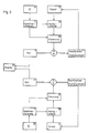
- FIG. 1 shows schematically the structure of a dampening unit 1 of an offset printing machine, not shown.
- the dampening unit 1 has an immersion roller 2, which dips with a circumferential region into a container 3 'containing a dampening solution.
- the dipping roller 2 interacts with a metering roller 3, which in turn bears against a dampening roller 4, which interacts with a plate cylinder 5, on the lateral surface of which an offset printing plate 6, not shown, is clamped.
- the outer surface of the offset printing plate 6 is scanned by an optical sensor device 7, which is formed by two sensors 8 spaced apart from one another in the printing format width direction.
- the sensors 8 are arranged such that they lie approximately in the longitudinal edge area of the pressure plate 6 on both sides.
- the sensors 8 are connected via lines 9 to a control device 10, which is preferably designed as a microprocessor.
- the control device 10 is connected to the machine control 11 of the offset printing press.
- An actuating device 14 which is only indicated schematically, is provided at each end region 12 or 13 of immersion roller 2 or metering roller 3.
- Each actuating device 14 has an electric actuator 15, which is connected to a position sensor 16.
- Each position sensor 16 is preferably designed as a potentiometer 17, which is connected via a line 18 to the control device 10 and forms a component of the latter.
- each actuating device 14 makes it possible to dive roller 2 and metering roller 3 in the direction of the respective double arrow 19 towards or away from each other. Accordingly, the rollers 2 and 3 can be inclined relative to one another by changing the contact pressure, but their axes 20 and 21 remain lying in one plane.
- the actuators 15 are controlled via lines 22 connected to the control device 10.
- the arrangement is designed according to the invention in such a way that, depending on the data recorded by the sensors 8, the control device 10 controls the actuators 15 in such a way that, via a corresponding pressure between the immersion roller 2 and the metering roller 3, the optimum dampening solution quantity required for the respective pressure is dependent on the subject is transferred to the surface of the offset printing plate 6.
- the axes 20 and 21 and / or the above-described inclination of the axes 20 and 21 can be shifted in parallel.
- An inclined position means that in one side area of the rollers there is a greater pressing pressure than in the other side area.
- the potentiometers 17 report the respective position of the actuators 15 to the control device 10.
- an optimal dampening solution guidance should be adequate for the subject and color guidance, the dampening solution supply values being determined before the actual printing process begins.
- the printing plate 6 is colored by ink Inking unit not shown in the figures. The procedure is such that color-free surfaces take on color in the production process. This process is called “toning" in the technical language. Due to the ink acceptance of areas that are actually ink-free, the printing plate 6 is "closed”. This process can take place without the addition of dampening solution or else with a low dampening solution supply.
- the procedure according to the invention is now such that, after the offset printing plate 6 has closed, a defined fountain solution supply or the enlargement of the fountain solution supply to a defined value is carried out, so that the color of the toned areas is reduced.
- the process of this color decrease is detected by the sensors 8.
- the data determined in this way are processed in the control device 10 and represent a measure of the dampening solution guidance to be set.
- the type of ink removal - which is also referred to as "free running" of the printing plate 6 - and also the time required for this or the corresponding number the necessary revolutions of the plate cylinder 5 form a measure of the dampening solution guidance to be set.
- the amount of dampening solution is adjusted by adjusting the pressure between the dipping roller 2 and metering roller 3, in particular also with the axes 20 and 21 of these rollers 2 and 3 inclined relative to one another.
- the control device 10 controls the actuators 15 accordingly via the lines 22.
- a corresponding position message is sent to the control device 10 via the potentiometers 17 and the lines 18.
- the lateral surface of the offset printing plate 6 is checked in a peripheral zone 23 (FIG. 2) which includes the area between the beginning of the plate 24 and the beginning of the subject 25.
- the optical scanning by the sensors 8 takes place - taking into account the direction of rotation of the plate cylinder 5, which is represented in FIG. 2 by the arrow 26 - following the longitudinal groove 27 of the plate cylinder 5 which serves to fasten the printing plate.
- the area up to Experience shows that subject 25 is most likely to undergo a change, since smearing or the like can be detected here as early as possible. As a result, the changes that occur as a result of the ink removal process will also occur in this area at an early stage.
- a rotary angle sensor 28 assigned to the plate cylinder 5 interacts with the sensor 8 in such a way that the surface of the offset printing plate 6 is queried in the area 23 described above.
- the sensor 8 monitors in itself color-free areas of the printing plate 6 with regard to an ink acceptance (toning). If a toning process occurs, the associated actuator 15 is controlled via the control device 10 in such a way that the dampening solution supply is increased in the section assigned to the sensor 8 by changing the pressing force between the immersion roller 2 and the metering roller 3 or the relative inclination of these rollers to one another.
- the respective actuator position is detected by the potentiometer 17 and can be displayed on a display 29.
- each end region 12 or 13 of immersion roller 2 or metering roller 3 is assigned an actuating device 14, the individual components are duplicated in FIG. 3.
- the dashed connecting line between the blocks "Tonen” makes it clear that the data originating from the sensors 8 can be compared with one another to generate a differential control signal.
- the method according to the invention for determining the dampening solution guidance of an offset printing press can also be carried out in such a way that a preferably small amount of dampening solution is first applied to the printing plate and then ink is supplied over the printing format width, depending on the subject, in such a way that ink-free in the production process Apply color to areas.
- the toning process thus established is detected by the sensors 8 and used as a measure of the dampening solution guidance to be corrected.
- the manner in which the offset printing plate 6 tilts with ink thus forms the information for the dampening solution supply to be carried out.
- a further variant consists in that a quantity of dampening solution is first applied to the printing plate 6, a subject-dependent ink supply is also carried out over the printing format width and then a reduction in the quantity of dampening solution is carried out, so that the toning process occurs. This toning process is in turn detected by the sensors and serves as a measure of the dampening solution guidance to be set.
- the application of the methods and devices according to the invention is not limited to the period before the actual printing process, but can also be used to monitor and correct the dampening solution management during the current printing process.
Landscapes
- Engineering & Computer Science (AREA)
- Mechanical Engineering (AREA)
- Inking, Control Or Cleaning Of Printing Machines (AREA)
- Rotary Presses (AREA)
Applications Claiming Priority (2)
| Application Number | Priority Date | Filing Date | Title |
|---|---|---|---|
| DE3912811 | 1989-04-19 | ||
| DE3912811A DE3912811A1 (de) | 1989-04-19 | 1989-04-19 | Verfahren und vorrichtung fuer die feuchtmittelfuehrung einer offset-druckmaschine |
Publications (3)
| Publication Number | Publication Date |
|---|---|
| EP0393365A2 true EP0393365A2 (fr) | 1990-10-24 |
| EP0393365A3 EP0393365A3 (fr) | 1991-05-22 |
| EP0393365B1 EP0393365B1 (fr) | 1994-08-31 |
Family
ID=6378972
Family Applications (1)
| Application Number | Title | Priority Date | Filing Date |
|---|---|---|---|
| EP90105186A Expired - Lifetime EP0393365B1 (fr) | 1989-04-19 | 1990-03-20 | Procédé et dispositif d'alimentation en liquide de mouillage d'une machine à imprimer en offset |
Country Status (5)
| Country | Link |
|---|---|
| US (1) | US5090316A (fr) |
| EP (1) | EP0393365B1 (fr) |
| JP (1) | JPH02295741A (fr) |
| CA (1) | CA2014950A1 (fr) |
| DE (2) | DE3912811A1 (fr) |
Cited By (5)
| Publication number | Priority date | Publication date | Assignee | Title |
|---|---|---|---|---|
| WO1994011192A1 (fr) * | 1992-11-14 | 1994-05-26 | Koenig & Bauer Aktiengesellschaft | Procede permettant d'influer sur la densite optique de la couche d'encre appliquee sur un support d'impression |
| EP0700782A3 (fr) * | 1994-09-06 | 1997-03-12 | Koenig & Bauer Albert Ag | Rouleau doseur dans un dispositif de mouillage d'une machine à imprimer offset |
| EP1261486A4 (fr) * | 2000-03-09 | 2005-03-23 | Commw Scient Ind Res Org | Encre et solution de mouillage de determination pour impression offset |
| WO2008049500A3 (fr) * | 2006-10-23 | 2008-09-18 | Fischer & Krecke Gmbh & Co Kg | Presse rotative et procédé pour ajuster un de ses cylindres |
| EP1477314B1 (fr) * | 2003-05-15 | 2011-01-05 | Dainippon Screen Mfg. Co., Ltd. | Procédé et dispositif pour commander l'alimentation en eau pour une machine d'impression offset |
Families Citing this family (20)
| Publication number | Priority date | Publication date | Assignee | Title |
|---|---|---|---|---|
| DE4436582C2 (de) * | 1994-10-13 | 1998-07-30 | Heidelberger Druckmasch Ag | Verfahren zur Regelung einer Feuchtmittelmenge für eine Druckform einer laufenden Offsetrotationsdruckmaschine |
| GB9426166D0 (en) * | 1994-12-23 | 1995-02-22 | Langston Corp | Printing apparatus |
| US5791249A (en) * | 1997-03-27 | 1998-08-11 | Quad/Tech, Inc. | System and method for regulating dampening fluid in a printing press |
| US5826507A (en) * | 1997-05-22 | 1998-10-27 | Union Camp Corporation | Method for measuring the amount of fountain solution in offset lithography printing |
| DE19960919C2 (de) * | 1999-12-17 | 2003-11-27 | Du Pont | Verfahren und Vorrichtung zur Messung optischer Parameter an flüssigen Medien |
| SE0003840L (sv) * | 2000-10-23 | 2002-04-24 | Baldwin Jimek Ab | Sätt och anordning för detektering av toning i en tryckpress |
| DE10058550A1 (de) * | 2000-11-24 | 2002-05-29 | Heidelberger Druckmasch Ag | Verfahren zur Regelung des Farb-zu-Feuchtmittelgleichgewichts in einer Rotations-Offsetdruckmaschine |
| DE10152466B4 (de) * | 2000-11-24 | 2015-12-17 | Heidelberger Druckmaschinen Ag | Feuchteregelung unter Berücksichtigung mehrerer den Druckprozess beeinflussender Größen |
| DE10320759B4 (de) * | 2002-06-10 | 2013-03-14 | Heidelberger Druckmaschinen Ag | Transportsystem mit Gebern zur Lageerfassung in einer bedruckstoffverarbeitenden Maschine |
| JP4638685B2 (ja) | 2003-06-10 | 2011-02-23 | ハイデルベルガー ドルツクマシーネン アクチエンゲゼルシヤフト | オフセット印刷機による印刷の際に湿し水を調量する方法 |
| US6796227B1 (en) | 2003-08-18 | 2004-09-28 | Quad Tech | Lithographic press dampening control system |
| US7225735B2 (en) * | 2004-05-03 | 2007-06-05 | Heidelberger Druckmaschinen Ag | Method for roller adjustment in a printing press |
| DE102004022084A1 (de) * | 2004-05-05 | 2005-12-08 | Man Roland Druckmaschinen Ag | Feuchtwerk für eine Druckmaschine |
| US20070125246A1 (en) * | 2005-12-05 | 2007-06-07 | Goss International Americas, Inc. | Apparatus and method for controlling delivery of dampener fluid in a printing press |
| US20100011978A1 (en) * | 2006-10-23 | 2010-01-21 | Fischer & Krecke Gmbh & Co. Kg | Rotary Printing Press and Method for Adjusting a Cylinder Thereof |
| PL1916102T5 (pl) * | 2006-10-23 | 2016-03-31 | Bobst Bielefeld Gmbh | Sposób regulacji ustawienia wałka w rotacyjnej maszynie drukarskiej |
| DE102008000416A1 (de) * | 2008-02-26 | 2009-09-03 | Isimat Gmbh Siebdruckmaschinen | Vorrichtung und Verfahren zum Bedrucken von Gegenständen |
| DE102009019022B4 (de) * | 2008-05-26 | 2021-07-01 | Heidelberger Druckmaschinen Ag | Verfahren zur Walzenjustage in einem Feuchtwerk einer Druckmaschine und Feuchtwerk einer Druckmaschine |
| DE102008061599A1 (de) * | 2008-12-11 | 2009-12-03 | Heidelberger Druckmaschinen Ag | Verfahren zum Einstellen eines Feuchtwerks einer Druckmaschine |
| DE102013001083A1 (de) * | 2012-02-17 | 2013-08-22 | Heidelberger Druckmaschinen Ag | Druckplatte für Offsetdruck mit Feuchtmittel |
Family Cites Families (18)
| Publication number | Priority date | Publication date | Assignee | Title |
|---|---|---|---|---|
| CA863048A (en) * | 1971-02-09 | R. Kantor Paul | Dampening control means for photo-offset lithography press | |
| US3433155A (en) * | 1965-09-13 | 1969-03-18 | Harris Intertype Corp | Mechanism for applying a coating to a plate |
| DE2054678C3 (de) * | 1970-11-06 | 1975-05-22 | Roland Offsetmaschinenfabrik Faber & Schleicher Ag, 6050 Offenbach | Feuchtwerk für lithographische Druckmaschinen |
| DE2214721B1 (de) * | 1972-03-25 | 1973-06-14 | Heidelberger Druckmaschinen Ag, 6900 Heidelberg | Verfahren und vorrichtung zum selbsttaetigen ausregeln von schwankungen der farb- und feuchtfluessigkeitsfuehrung an offsetmaschinen |
| IT1033240B (it) * | 1974-03-14 | 1979-07-10 | Grapho Metronic Gmbh & Co | Umidificatore in una macchina stampatrice offset con un dispositivo per la regolazione del quantitativo d acqua sulla piastra |
| DE2530109C3 (de) * | 1975-07-05 | 1978-05-03 | Heidelberger Druckmaschinen Ag, 6900 Heidelberg | Farbwerk für Druckmaschinen |
| DE2947791C2 (de) * | 1979-11-28 | 1985-04-18 | Licentia Patent-Verwaltungs-Gmbh, 6000 Frankfurt | Einrichtung zur Farbüberwachung von bogen- oder bahnförmigen, in Bewegung befindlichen Materialien, insbesondere der Druckmaterialien von Druckmaschinen |
| DE3105020A1 (de) * | 1981-02-12 | 1982-09-02 | M.A.N.- Roland Druckmaschinen AG, 6050 Offenbach | Vorrichtung zum aufbringen eines fluids, insbesondere von lacken auf bedruckte bogen oder bahnen |
| JPS57163572A (en) * | 1981-04-01 | 1982-10-07 | Ryobi Ltd | Automatic water adjuster for offset press |
| JPS58116153A (ja) * | 1981-12-29 | 1983-07-11 | Komori Printing Mach Co Ltd | 巻紙輪転印刷機の給水着ロ−ラ装置 |
| DE3211157A1 (de) * | 1982-03-26 | 1983-10-06 | Roland Man Druckmasch | Verfahren und vorrichtung zum befeuchten von druckplatten |
| AT389675B (de) * | 1982-06-02 | 1990-01-10 | Heidelberger Druckmasch Ag | Vorrichtung zur farbprofilabhaengigen feuchtmittelregelung |
| DE3220701C3 (de) * | 1982-06-02 | 1995-09-07 | Heidelberger Druckmasch Ag | Vorrichtung zur Feuchtmittelführung bei einem Offsetdruckwerk |
| DE3238912C1 (de) * | 1982-10-21 | 1984-03-15 | M.A.N.- Roland Druckmaschinen AG, 6050 Offenbach | Vorrichtung zum zonenweisen Abtasten der Einfaerbung eines Plattenzylinders einer Rotations-Offsetdruckmaschine |
| JPS59135158A (ja) * | 1983-01-21 | 1984-08-03 | Nireko:Kk | 印刷における湿し水供給量の制御方法 |
| US4480542A (en) * | 1983-12-23 | 1984-11-06 | Heidelberger Druckmaschinen | Device for ink profile-dependent regulation of dampening medium |
| US4972774A (en) * | 1985-04-29 | 1990-11-27 | Baldwin Technology Corporation | Automatically controlling water feedrate on a lithographic press |
| JPS6316224A (ja) * | 1986-07-08 | 1988-01-23 | Oval Eng Co Ltd | 渦流量計 |
-
1989
- 1989-04-19 DE DE3912811A patent/DE3912811A1/de not_active Ceased
-
1990
- 1990-03-20 DE DE59006941T patent/DE59006941D1/de not_active Expired - Fee Related
- 1990-03-20 EP EP90105186A patent/EP0393365B1/fr not_active Expired - Lifetime
- 1990-04-19 JP JP2101855A patent/JPH02295741A/ja active Pending
- 1990-04-19 CA CA002014950A patent/CA2014950A1/fr not_active Abandoned
- 1990-04-19 US US07/511,057 patent/US5090316A/en not_active Expired - Lifetime
Cited By (7)
| Publication number | Priority date | Publication date | Assignee | Title |
|---|---|---|---|---|
| WO1994011192A1 (fr) * | 1992-11-14 | 1994-05-26 | Koenig & Bauer Aktiengesellschaft | Procede permettant d'influer sur la densite optique de la couche d'encre appliquee sur un support d'impression |
| US5568769A (en) * | 1992-11-14 | 1996-10-29 | Koenit & Bauer Aktiengesellschaft | Process for influencing the optical density of a printing ink layer on a print carrier |
| EP0700782A3 (fr) * | 1994-09-06 | 1997-03-12 | Koenig & Bauer Albert Ag | Rouleau doseur dans un dispositif de mouillage d'une machine à imprimer offset |
| EP1261486A4 (fr) * | 2000-03-09 | 2005-03-23 | Commw Scient Ind Res Org | Encre et solution de mouillage de determination pour impression offset |
| EP1477314B1 (fr) * | 2003-05-15 | 2011-01-05 | Dainippon Screen Mfg. Co., Ltd. | Procédé et dispositif pour commander l'alimentation en eau pour une machine d'impression offset |
| WO2008049500A3 (fr) * | 2006-10-23 | 2008-09-18 | Fischer & Krecke Gmbh & Co Kg | Presse rotative et procédé pour ajuster un de ses cylindres |
| US8534194B2 (en) | 2006-10-23 | 2013-09-17 | Bobst Bielefeld Gmbh | Rotary printing press and method for adjusting a cylinder thereof |
Also Published As
| Publication number | Publication date |
|---|---|
| CA2014950A1 (fr) | 1990-10-19 |
| US5090316A (en) | 1992-02-25 |
| DE59006941D1 (de) | 1994-10-06 |
| JPH02295741A (ja) | 1990-12-06 |
| EP0393365A3 (fr) | 1991-05-22 |
| DE3912811A1 (de) | 1990-10-25 |
| EP0393365B1 (fr) | 1994-08-31 |
Similar Documents
| Publication | Publication Date | Title |
|---|---|---|
| EP0393365B1 (fr) | Procédé et dispositif d'alimentation en liquide de mouillage d'une machine à imprimer en offset | |
| DE3445012C2 (de) | Rollen-Rotations-Flexodruckmaschine | |
| DE3800570C2 (fr) | ||
| DE69218141T2 (de) | Beschichtungsverfahren, Beschichtungsvorrichtung und Beschichtungsdüse | |
| DE20122584U1 (de) | Einheit zur Einstellung des Druckbildes in einer Rotationsdruckmaschine | |
| DE4436953C1 (de) | Verfahren zur Erzeugung einer Farbschichtdickenverteilung auf Farbwerkwalzen eines Farbwerkes einer Druckmaschine | |
| DE4012825C2 (fr) | ||
| EP0364736B1 (fr) | Méthode de détermination de la consommation d'encre dans une machine d'impression offset | |
| DE3217569C2 (de) | Verfahren und Vorrichtung zum Dosieren der Farbe bei Offsetdruckmaschinen | |
| EP0132624B1 (fr) | Dispositif de contrôle par zones de l'alimentation en agent de mouillage dans l'encrier d'une machine à imprimer offset, au moyen de techniques de mesure | |
| AT389675B (de) | Vorrichtung zur farbprofilabhaengigen feuchtmittelregelung | |
| DE2259085A1 (de) | Farbwerk fuer flachdruckmaschinen | |
| DE10211870B4 (de) | Verfahren zur Justierung zweier aneinander anlegbarer Walzen eines Druckwerks | |
| EP0623468A1 (fr) | Dispositif d'encrage à rouleau preneur et procédé pour régler l'alimentation en encre dans des machines d'impression | |
| EP2418083B1 (fr) | Dispositif de régulation du taux d'agent d'humidification et du taux de couleur dans une presse | |
| DE19520841A1 (de) | Farbwerk für ein Offsetdruckwerk und Verfahren zum Einfärben und Feuchten der Druckform | |
| DE10159698A1 (de) | Verfahren und Vorrichtung zum Einstellen einer Farbmenge, die einem Druckzylinder einer Druckmaschine zugeführt wird | |
| DE4436582C2 (de) | Verfahren zur Regelung einer Feuchtmittelmenge für eine Druckform einer laufenden Offsetrotationsdruckmaschine | |
| DE3034588C2 (de) | Offset-Rotationsdruckmaschine mit einer Einrichtung zur Unterbrechung der Feuchtmittelzufuhr | |
| DE3924376C2 (de) | Verfahren zur Farbmengenmessung für ein Heberfarbwerk einer Druckmaschine | |
| EP1216833B1 (fr) | Méthode de régulation de l'équilibre encre-solution de mouillage dans une machine d'impression rotative | |
| DE3638813C2 (fr) | ||
| DE10204514B4 (de) | Vorrichtung und Verfahren zur Korrektur des Längsregisterfehlers, welcher durch die Beistellung auftritt | |
| DE2945894C2 (de) | Farbkastenwalzenantriebseinrichtung eines Farbwerkes für Druckmaschinen | |
| DE2346016A1 (de) | Verfahren und anordnung zur durchfuehrung des verfahrens zur feuchtigkeitsmessung beim lithographischen drucken |
Legal Events
| Date | Code | Title | Description |
|---|---|---|---|
| PUAI | Public reference made under article 153(3) epc to a published international application that has entered the european phase |
Free format text: ORIGINAL CODE: 0009012 |
|
| 17P | Request for examination filed |
Effective date: 19900320 |
|
| AK | Designated contracting states |
Kind code of ref document: A2 Designated state(s): DE ES FR GB IT NL |
|
| PUAL | Search report despatched |
Free format text: ORIGINAL CODE: 0009013 |
|
| AK | Designated contracting states |
Kind code of ref document: A3 Designated state(s): DE ES FR GB IT NL |
|
| 17Q | First examination report despatched |
Effective date: 19930211 |
|
| RBV | Designated contracting states (corrected) |
Designated state(s): DE FR GB |
|
| GRAA | (expected) grant |
Free format text: ORIGINAL CODE: 0009210 |
|
| AK | Designated contracting states |
Kind code of ref document: B1 Designated state(s): DE FR GB |
|
| PG25 | Lapsed in a contracting state [announced via postgrant information from national office to epo] |
Ref country code: FR Free format text: THE PATENT HAS BEEN ANNULLED BY A DECISION OF A NATIONAL AUTHORITY Effective date: 19940831 |
|
| REF | Corresponds to: |
Ref document number: 59006941 Country of ref document: DE Date of ref document: 19941006 |
|
| ET | Fr: translation filed | ||
| GBT | Gb: translation of ep patent filed (gb section 77(6)(a)/1977) |
Effective date: 19941121 |
|
| PG25 | Lapsed in a contracting state [announced via postgrant information from national office to epo] |
Ref country code: GB Effective date: 19950320 |
|
| PLBI | Opposition filed |
Free format text: ORIGINAL CODE: 0009260 |
|
| 26 | Opposition filed |
Opponent name: KOENIG & BAUER AG Effective date: 19950531 |
|
| GBPC | Gb: european patent ceased through non-payment of renewal fee |
Effective date: 19950320 |
|
| PLAB | Opposition data, opponent's data or that of the opponent's representative modified |
Free format text: ORIGINAL CODE: 0009299OPPO |
|
| REG | Reference to a national code |
Ref country code: FR Ref legal event code: ST |
|
| R26 | Opposition filed (corrected) |
Opponent name: KBA KOENIG & BAUER-ALBERT AG WERK WUERZBURG Effective date: 19950531 |
|
| PLBL | Opposition procedure terminated |
Free format text: ORIGINAL CODE: EPIDOS OPPC |
|
| PLBM | Termination of opposition procedure: date of legal effect published |
Free format text: ORIGINAL CODE: 0009276 |
|
| STAA | Information on the status of an ep patent application or granted ep patent |
Free format text: STATUS: OPPOSITION PROCEDURE CLOSED |
|
| 27C | Opposition proceedings terminated |
Effective date: 19960503 |
|
| PGFP | Annual fee paid to national office [announced via postgrant information from national office to epo] |
Ref country code: DE Payment date: 20070326 Year of fee payment: 18 |
|
| PG25 | Lapsed in a contracting state [announced via postgrant information from national office to epo] |
Ref country code: DE Free format text: LAPSE BECAUSE OF NON-PAYMENT OF DUE FEES Effective date: 20081001 |