EP0393410A2 - Appareil aérospatial avec deux hélices tournant en sens inverse - Google Patents
Appareil aérospatial avec deux hélices tournant en sens inverse Download PDFInfo
- Publication number
- EP0393410A2 EP0393410A2 EP90106212A EP90106212A EP0393410A2 EP 0393410 A2 EP0393410 A2 EP 0393410A2 EP 90106212 A EP90106212 A EP 90106212A EP 90106212 A EP90106212 A EP 90106212A EP 0393410 A2 EP0393410 A2 EP 0393410A2
- Authority
- EP
- European Patent Office
- Prior art keywords
- sectors
- rotors
- aircraft according
- aircraft
- rotor
- Prior art date
- Legal status (The legal status is an assumption and is not a legal conclusion. Google has not performed a legal analysis and makes no representation as to the accuracy of the status listed.)
- Granted
Links
- 241000446313 Lamella Species 0.000 claims description 20
- 238000000034 method Methods 0.000 description 7
- 230000008569 process Effects 0.000 description 7
- 230000007704 transition Effects 0.000 description 4
- 238000010276 construction Methods 0.000 description 3
- 239000007789 gas Substances 0.000 description 3
- 229920001971 elastomer Polymers 0.000 description 2
- 230000005484 gravity Effects 0.000 description 2
- 230000001141 propulsive effect Effects 0.000 description 2
- 206010000369 Accident Diseases 0.000 description 1
- 229920000049 Carbon (fiber) Polymers 0.000 description 1
- 239000004917 carbon fiber Substances 0.000 description 1
- 238000006243 chemical reaction Methods 0.000 description 1
- 238000013016 damping Methods 0.000 description 1
- 230000007423 decrease Effects 0.000 description 1
- 238000006073 displacement reaction Methods 0.000 description 1
- 230000000694 effects Effects 0.000 description 1
- 239000000806 elastomer Substances 0.000 description 1
- 239000002828 fuel tank Substances 0.000 description 1
- 230000005283 ground state Effects 0.000 description 1
- 230000003993 interaction Effects 0.000 description 1
- 239000003562 lightweight material Substances 0.000 description 1
- 239000000463 material Substances 0.000 description 1
- VNWKTOKETHGBQD-UHFFFAOYSA-N methane Chemical compound C VNWKTOKETHGBQD-UHFFFAOYSA-N 0.000 description 1
- 230000007935 neutral effect Effects 0.000 description 1
- 229920001084 poly(chloroprene) Polymers 0.000 description 1
- 239000002990 reinforced plastic Substances 0.000 description 1
- 238000005096 rolling process Methods 0.000 description 1
- 239000007787 solid Substances 0.000 description 1
- 239000003381 stabilizer Substances 0.000 description 1
- 230000000087 stabilizing effect Effects 0.000 description 1
Images


Classifications
-
- B—PERFORMING OPERATIONS; TRANSPORTING
- B64—AIRCRAFT; AVIATION; COSMONAUTICS
- B64C—AEROPLANES; HELICOPTERS
- B64C27/00—Rotorcraft; Rotors peculiar thereto
- B64C27/20—Rotorcraft characterised by having shrouded rotors, e.g. flying platforms
-
- B—PERFORMING OPERATIONS; TRANSPORTING
- B64—AIRCRAFT; AVIATION; COSMONAUTICS
- B64C—AEROPLANES; HELICOPTERS
- B64C29/00—Aircraft capable of landing or taking-off vertically, e.g. vertical take-off and landing [VTOL] aircraft
- B64C29/0008—Aircraft capable of landing or taking-off vertically, e.g. vertical take-off and landing [VTOL] aircraft having its flight directional axis horizontal when grounded
- B64C29/0016—Aircraft capable of landing or taking-off vertically, e.g. vertical take-off and landing [VTOL] aircraft having its flight directional axis horizontal when grounded the lift during taking-off being created by free or ducted propellers or by blowers
- B64C29/0025—Aircraft capable of landing or taking-off vertically, e.g. vertical take-off and landing [VTOL] aircraft having its flight directional axis horizontal when grounded the lift during taking-off being created by free or ducted propellers or by blowers the propellers being fixed relative to the fuselage
-
- B—PERFORMING OPERATIONS; TRANSPORTING
- B64—AIRCRAFT; AVIATION; COSMONAUTICS
- B64C—AEROPLANES; HELICOPTERS
- B64C39/00—Aircraft not otherwise provided for
- B64C39/001—Flying saucers
Definitions
- the invention relates to an aircraft with an oppositely rotating pair of rotors for generating lift and propulsion.
- Aircraft of this type are generally known in the form of helicopters.
- helicopters are known which have several rotors rotating in opposite directions, which results in a torque compensation between the rotors. As is known, these can be arranged one above the other.
- the rotor axis is located in the center of gravity of the aircraft, which limits the usable space.
- the mechanical design of the drive and control is extremely complex, particularly in the case of rotors arranged one above the other.
- the control functions are complicated and require great skill.
- the speed in forward flight is limited by the asymmetry of the flow against the rotor blades and the resulting mechanical loads on the rotors. After all, the free rotors are often the cause of aircraft accidents, since even the slightest contact with solid objects leads to unforeseeable effects on the lift characteristics and the controllability of the aircraft.
- Rotary wing aircraft with counter-rotating rotors are known, for example, from Swiss Patent No. 558 737, from Australian PS No. 474 805 and from US Pat. Nos. 2,777,649, 2,395,876 and 2,461,435, the rotors being partially arranged within a housing and air ducts being provided.
- the arrangement of the air ducts or fins does not allow safe control of the flight positions and movements of these aircraft in hover. Further the control processes are confusing and complicated, so that difficulties in mastering these aircraft may occur in practical operation.
- the object is to create an aircraft of the type mentioned at the outset which does not have these disadvantages and which, in particular, enables two flight states, namely a helicopter-like hover and a surface flight, without control problems occurring.
- this object is achieved by the features of claim 1.
- the mutually opposing arrangement of the blades in the sectors active during hover allows a controlled hover without unwanted propulsion components.
- the air ducts preferably have propulsion areas in which the blades can be controlled in the same direction with respect to the rotor beam. These areas are used to generate propulsion in surface flight and hover as well as to control the position around the vertical axis in hover.
- controllable air ducts are sector-oriented, tangentially extending slats, the slat sectors each comprising approximately 30 degrees and each having a control drive, the control drives being interconnectable in groups according to the control signals.
- the movement of the aircraft can be controlled in a simple manner by suitable interaction of the deflection of the rotor beam in each of the interconnected groups.
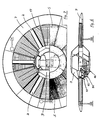
- the basic element is a housing 1, in which a pair of rotors 2, 3 is arranged, which is driven in opposite directions.
- the housing 1 itself is disc-shaped. In its longitudinal cross-section, it has a profile that generates lift when the flow is against it, while it is essentially circular in plan.
- the housing thus forms a circular wing which, in addition to hovering, also permits flight conditions which correspond to those of fixed-wing aircraft, ie. powered forward flight or gliding flight.
- the propulsion is at least to a considerable extent by the pair of rotors 2, 3 with appropriate deflections and guidance of the rotor beam, as will be explained in more detail.
- a cabin 9 is provided for receiving the drive unit 8, the pilot, the passengers and the payload.
- the cabin 9 is radially delimited by a twelve-sided, cylindrical support part 4, on which struts 17 with a triangular profile lead in the radial direction to an annular outer part 7.
- the elements mentioned together form a load-bearing, rigid structure. They are preferably made of high-strength, lightweight material, such as e.g. carbon fiber or Kevlar-reinforced plastic.
- the cylindrical support part 4 forms a central, open space in which the cabin 9 is formed, which in the exemplary embodiment shown is mainly in the rotor plane in the inner part 4 itself, is accessible from above and offers space for two people.
- the drive and control units are located in the lower or rear area of the inner part 4 in the direction of flight.
- Bearing rollers 11 are provided on the supporting part 4, on which the rotors 2, 3 with their inner drive rings 12 are mounted, as can be seen in particular from FIG. 5. To absorb axial forces, these bearings 11 are set at an angle to the rotor plane.
- the drive rings 12 can advantageously directly form parts of the bearing itself.
- Fixed guides 10 are provided on the annular outer part 7, on which outer rollers 34 run, which are arranged on the outside of the rotor blades (cf. FIG. 2).
- the outer guides 10 and the run-off surfaces of the bearing rollers are provided with a noise-damping elastomer material, for example a resistant rubber such as neoprene.
- a noise-damping elastomer material for example a resistant rubber such as neoprene.
- the outer guidance of the rotor blades can be dispensed with if they are designed to be sufficiently rigid so that their deflection under load remains within the tolerances given by the design.
- each rotor which, according to the embodiments shown here, each rotor extend between the inner drive ring 12 and the outer guide 10, have a suitable, buoyancy-generating blade profile.
- the rotors 2, 3 are driven by means of a common unit 8, which is arranged in the cylindrical inner part 4.
- the unit is a piston engine with an output of e.g. 220 WPS. This drives two gears 19 via a gear, which mesh in the two drive rings 12 of the rotors 2, 3.
- Another exemplary embodiment with a jet turbine drive will be explained with reference to FIGS. 6 and 7.
- the drive causes the rotor to rotate in exactly the opposite direction, which leads to complete torque compensation. Any residual torques that may occur on the housing 1 can be trimmed or corrected using the control system to be described.
- the housing parts above and below the rotor level are designed for sufficient air passage.
- the upper cover which does not have to have a supporting function, is formed by an outer skin 5 with air openings.
- the air inlets can be designed, for example, as mesh grids arranged in sectors.
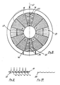
- Below the rotor plane louvre-like, tangential, adjustable fins 16 are arranged in sectors, as shown in particular in FIG. 3 and 4 can be seen. In the exemplary embodiment shown, the sectors have angles of 30 degrees, so that a total of 12 such sectors result.
- sectors and their functions can be seen on the basis of a first embodiment variant.
- the sectors a, b, d, e, g, h, k, l belong to the first group (cf. FIG. 4).
- the slats in these sectors can be adjusted in pairs in opposite directions with respect to the rotor beam by means of cables 31, 31 '.
- the trains 31,31 ' are each connected to a servo drive 18 for slat adjustment.
- the aforementioned opposing pairwise adjustment means that the sectors mentioned in the first group do not generate a propulsion component, but rather only a certain buoyancy force in each position.
- the slats of the individual sectors can be opened more or less, so that the lifting force in the corresponding sector increases or decreases.
- the rolling motion i.e. the inclination about the longitudinal axis 32 (FIG. 4) is accomplished by the corresponding control of the sector groups b, d and h, k.
- the pitching motion in hover i.e. the inclination around the transverse axis is carried out by controlling the sector groups a, l and g, e.
- the total lifting force, which causes the aircraft to rise or fall vertically, is brought about by collective opening and closing of the aforementioned lamella groups.
- the lamellae of a second group are from Sectors m, f and c, i and optionally also individual ones of the sectors of the first group can be adjusted in the same direction, so that a corresponding horizontal propulsive force is superimposed on the buoyant force in the area of the respective sector.
- propulsion units independent of the lamella control can be provided for the horizontal surface flight, as will be explained in more detail.
- the slats of the first sector group mentioned are closed and form part of a lift-generating profile.
- the propulsion in this flight state is generated by the additional propulsion units still to be described and / or by the correspondingly inclined slats of the sectors m and f and slat groups 33.
- the latter determine the cornering behavior in surface flight by optionally changing the angle of attack to the left or right of the direction of flight 32.
- the lamella sectors m and f are also closed to improve the gliding properties.
- stabilizing wings 40 arranged in the annular outer part 7 can be extended (see FIGS. 1 and 2), which are sunk in the outer part 7 when hovering.
- the lightweight outer ring 7 of the housing optionally carries the guides 10 of the rotors and is on the struts 17 be consolidates.
- fuel tanks, a retractable roller carriage 41 and possibly additional propulsion units 42 can also be arranged (FIGS. 3, 4).
- the structure of the rotor housing 1 and outer part 7 is essentially identical in sectors, so that a modular construction with relatively few components is possible.
- the profile of the outer part 7, together with the rotor housing, is such that it generates lift in forward flight, i.e. acts as a round wing.
- hover flight A general distinction must be made between hover flight and area flight for the control behavior.
- hovering the lift and propulsion are generated by the rotors, while in gliding flight a substantial part of the lift is taken over by the correspondingly profiled housing 1 and outer ring 7 and part of the propulsion by propulsion units.
- control is also carried out in a different way, as has already been indicated.
- control elements are connected to control electronics which, according to a control program, actuate the respective servo drives 18 of the slat sectors.
- the changeover between hovering and surface flight takes place automatically depending on the forward speed as soon as the inflow speed on the housing profile ensures a corresponding lift.
- the functioning of the control elements remains unaffected by this, so that the control can be operated in the same way for both flight conditions.
- the directional stability and the horizontal position of the aircraft when the control elements are not actuated is controlled in a manner known per se by an automatic slat control Dependence of a position sensor system is observed, on which the signals of the control elements are superimposed.
- the first of the two control elements in the form of a control stick influences the horizontal displacements in hover flight, while the second control element, also in the form of a control stick, controls the inclinations about the longitudinal and transverse axes in hover flight or in flat flight.
- the lamella profile can be bent in these sectors for better deflection of the rotor beam, such that a beam deflection of approximately 70 ° is accomplished, as is shown in FIG. 9 with the lamella position open towards one side and in FIG. 10 with the lamella position closed. The losses caused by the beam deflection can thus be reduced.
- the same slat groups are used for corresponding control processes in hovering and in flat flight, one from the open and the other from the essentially closed ground state.
- the second control element is intended for rotations around the three body axes, which enables the necessary control processes in surface flight.
- a recoil drive acting in the horizontal direction is provided as a variant in addition to the described lamella groups m and f and the lamella groups 33.
- This can be independent of the drive of the rotor pair, as indicated in FIGS. 3 and 4.
- two jet turbine engines 42 are arranged laterally to the main flight direction in the annular outer part.
- a flap 43 of known type is provided in the exit area for deflecting the jet in the vertical direction during hovering.
- the thrust generated only needs to be a fraction of the starting weight of approx. 1100 kp, since the buoyancy is mainly generated by the rotors 2; 3 in hover.
- the jet engines take over a significant part of the propulsion.
- a propeller can also be arranged at the top of the outer ring 7, which can be coupled to the drive unit for surface flight.
- a turbine 44 which is arranged in the cabin 9 between the seats, serves both to drive the rotors and to generate propulsion.
- the turbine drives the rotors via a gear 45 (schematically), as already described above.
- the turbine exhaust gases act as a jet drive, the jet being able to be brought into the vertical and deflected positions by means of flaps 46.
- the air intake opening 47 is arranged on the underside of the cabin. In hover, the flaps 46 deflect the turbine exhaust gases in the vertical direction and thus contribute to the lift (FIG. 6).
- the exhaust gas jet enters and exits essentially horizontally in flat flight.
- FIG. 8 A further embodiment of the aircraft according to the invention with a modified lamella arrangement is shown in FIG. 8.
- sectors c and i serve to generate propulsion by deflecting the rotor beam.
- the fins 27 in these sectors run transversely to the flight direction and preferably have a profile according to FIGS. 9 and 10, which reduces the losses when the rotor beam is deflected. Since with this arrangement four sectors are opened evenly distributed over the circumference of the rotor beam, a uniform pressure distribution is established in the rotor housing. For the rest, reference can be made to the above statements regarding the individual control processes.
- the aircraft designed in the manner described can be designed as an unmanned drone or as a manned aircraft. It combines the advantages of the helicopter with those of a plane.
- the aircraft can in particular perform all helicopter maneuvers without, however, being exposed to the risk of rotor contact and without a pendulum movement with respect to the vertical axis, which is eliminated by the controlled air guidance. With this, the aircraft can e.g. Approach objects with direct contact for rescue operations.
- all flight maneuvers of a conventional aircraft can be carried out.
- roll landings can be carried out.
- the aircraft In the event of engine failure, the aircraft can be emergency landed from a low altitude thanks to the low specific wing load.
- stabilizers 40 (FIG. 2) are provided on the housing for control purposes.
- the aircraft described can be used economically over longer distances, which is ensured by the high load rating after the transition to the gliding surface.
- the controls are very simple, using natural, corresponds to human reactions and takes place exclusively with the hands, so that in particular a foot pedal operation is not required.
- the construction is also simple because of the essentially rotationally symmetrical design of the supporting parts compared to conventional aircraft construction in that the individual sectors can be largely manufactured uniformly
Landscapes
- Engineering & Computer Science (AREA)
- Aviation & Aerospace Engineering (AREA)
- Mechanical Engineering (AREA)
- Toys (AREA)
- Turbine Rotor Nozzle Sealing (AREA)
- Permanent Magnet Type Synchronous Machine (AREA)
- Structures Of Non-Positive Displacement Pumps (AREA)
- Supercharger (AREA)
- Tires In General (AREA)
- Retarders (AREA)
Applications Claiming Priority (2)
| Application Number | Priority Date | Filing Date | Title |
|---|---|---|---|
| CH149289 | 1989-04-19 | ||
| CH1492/89 | 1989-04-19 |
Publications (3)
| Publication Number | Publication Date |
|---|---|
| EP0393410A2 true EP0393410A2 (fr) | 1990-10-24 |
| EP0393410A3 EP0393410A3 (fr) | 1991-07-03 |
| EP0393410B1 EP0393410B1 (fr) | 1994-05-25 |
Family
ID=4211725
Family Applications (1)
| Application Number | Title | Priority Date | Filing Date |
|---|---|---|---|
| EP90106212A Expired - Lifetime EP0393410B1 (fr) | 1989-04-19 | 1990-03-31 | Appareil aérospatial avec deux hélices tournant en sens inverse |
Country Status (9)
| Country | Link |
|---|---|
| US (1) | US5064143A (fr) |
| EP (1) | EP0393410B1 (fr) |
| JP (1) | JPH0367799A (fr) |
| AT (1) | ATE106052T1 (fr) |
| BR (1) | BR9001816A (fr) |
| CA (1) | CA2014774A1 (fr) |
| DE (1) | DE59005795D1 (fr) |
| ES (1) | ES2054133T3 (fr) |
| SU (1) | SU1838180A3 (fr) |
Cited By (3)
| Publication number | Priority date | Publication date | Assignee | Title |
|---|---|---|---|---|
| EP0553490A1 (fr) * | 1992-01-29 | 1993-08-04 | Sky Disc Holding SA | Appareil volant |
| AT398298B (de) * | 1991-12-19 | 1994-11-25 | Almer Josef | Tragschrauber-fluggerät |
| WO2014026574A1 (fr) * | 2012-08-16 | 2014-02-20 | Chai Guijing | Dispositif de commande de vol pour aéronef en forme de soucoupe à double spirale |
Families Citing this family (71)
| Publication number | Priority date | Publication date | Assignee | Title |
|---|---|---|---|---|
| WO1992001603A1 (fr) * | 1990-07-25 | 1992-02-06 | Sadleir Vtol Aircraft Co. Pty. Ltd. | Unite de propulsion pour avion a decollage vertical et a atterrissage vertical |
| US5240204A (en) * | 1991-07-19 | 1993-08-31 | Kunz Bernard P | Lift generating method and apparatus for aircraft |
| US5150857A (en) * | 1991-08-13 | 1992-09-29 | United Technologies Corporation | Shroud geometry for unmanned aerial vehicles |
| EP0861775B1 (fr) * | 1992-06-22 | 2002-11-20 | United Technologies Corporation | Un sous-ensemble de moyeux de transmission/centrage coaxiales pour ensemble rotor |
| US5351911A (en) * | 1993-01-06 | 1994-10-04 | Neumayr George A | Vertical takeoff and landing (VTOL) flying disc |
| DE4439073C1 (de) * | 1994-11-02 | 1996-05-15 | Kunkel Klaus Dr Ing | Diskusförmiger Flugkörper mit einer Strahltriebwerks- und einer Raketentriebwerksanordnung |
| US5653404A (en) * | 1995-04-17 | 1997-08-05 | Ploshkin; Gennady | Disc-shaped submersible aircraft |
| US5730391A (en) * | 1995-06-05 | 1998-03-24 | Miller, Jr.; John A. | Universal fluid-dynamic body for aircraft and watercraft |
| US6308912B1 (en) * | 1997-10-21 | 2001-10-30 | Natural Colour Kari Kirjavainen Oy | Rotorcraft |
| RU2147546C1 (ru) * | 1998-08-06 | 2000-04-20 | Бирюков Сергей Михайлович | Летательный аппарат бирюкова |
| WO2000040464A2 (fr) * | 1998-12-11 | 2000-07-13 | Moller International, Inc. | Dispositif stabilisateur de commande pour plate-forme volante robotisee ou telecommandee |
| US6170778B1 (en) * | 1999-04-22 | 2001-01-09 | Sikorsky Aircraft Corporation | Method of reducing a nose-up pitching moment on a ducted unmanned aerial vehicle |
| NO310402B1 (no) * | 2000-02-01 | 2001-07-02 | Simicon As | Anordning ved et horisontalt og vertikalt flyvende luftfartöy |
| US7410123B2 (en) * | 2000-05-15 | 2008-08-12 | Nunnally William C | Aircraft and hybrid with magnetic airfoil suspension and drive |
| CN2437594Y (zh) * | 2000-05-17 | 2001-07-04 | 高恒伟 | 环翼直升机 |
| IL138695A (en) * | 2000-09-26 | 2004-08-31 | Rafael Armament Dev Authority | Unmanned mobile device |
| US6464166B1 (en) | 2001-05-29 | 2002-10-15 | Romeo Yankee Ltd. | Ducted fan vehicles particularly useful as VTOL aircraft |
| US7275712B2 (en) * | 2002-05-28 | 2007-10-02 | Urban Aeronautics, Ltd. | Ducted fan vehicles particularly useful as VTOL aircraft |
| US6883748B2 (en) | 2001-06-04 | 2005-04-26 | Rafi Yoeli | Vehicles particularly useful as VTOL vehicles |
| US6575401B1 (en) * | 2001-08-07 | 2003-06-10 | Howard J. Carver | Vertical-lift and horizontal flight aircraft |
| USD465196S1 (en) | 2001-12-14 | 2002-11-05 | Michael Dammar | Four propeller helicopter |
| US20040094662A1 (en) * | 2002-01-07 | 2004-05-20 | Sanders John K. | Vertical tale-off landing hovercraft |
| WO2004101357A2 (fr) | 2002-08-30 | 2004-11-25 | Qaxu Technology Inc. | Aeroglisseur volant homeostatique |
| US6834829B2 (en) | 2003-01-02 | 2004-12-28 | Percy E. Dunagin, Jr. | Vertical lift aircraft having an enclosed rotary wing |
| US7059931B2 (en) * | 2003-05-27 | 2006-06-13 | Veratech Aero-Rpv Corporation | Reduced visibility rotorcraft and method of controlling flight of reduced visibility rotorcraft |
| RU2249541C2 (ru) * | 2003-06-25 | 2005-04-10 | Гарипов Талгат Хайдарович | Летательный аппарат с вертикальным взлетом |
| FI20031095A7 (fi) * | 2003-07-22 | 2005-01-23 | Kari Johannes Kirjavainen | Virtausohjattu lento- ja pintaliitolaite |
| US7857253B2 (en) | 2003-10-27 | 2010-12-28 | Urban Aeronautics Ltd. | Ducted fan VTOL vehicles |
| JP2008526599A (ja) | 2005-01-10 | 2008-07-24 | アーバン エアロノーティクス リミテッド | ダクト内ファン垂直離着陸ビークル |
| US7946528B2 (en) | 2005-04-15 | 2011-05-24 | Urban Aeronautics, Ltd. | Flight control system especially suited for VTOL vehicles |
| US7717368B2 (en) | 2005-06-07 | 2010-05-18 | Urban Aeronautics Ltd. | Apparatus for generating horizontal forces in aerial vehicles and related method |
| US7559506B2 (en) * | 2005-09-14 | 2009-07-14 | Kissel Jr Waldemar F | Integral powered wing aircraft |
| WO2007099543A2 (fr) * | 2006-03-01 | 2007-09-07 | Urban Aeronautics Ltd. | Disposition d'aubes à effet de sol |
| WO2008065654A2 (fr) | 2006-11-27 | 2008-06-05 | Urban Aeronautics Ltd. | Effets de paroi sur des véhicules à décollage et atterrissage verticaux |
| US8496200B2 (en) | 2007-05-02 | 2013-07-30 | Urban Aeronautics Ltd. | Control flows and forces in VTOL vehicles |
| US8220737B2 (en) * | 2008-06-06 | 2012-07-17 | Frontline Aerospace, Inc. | VTOL aerial vehicle |
| US20100051754A1 (en) * | 2008-08-27 | 2010-03-04 | Davidson Robert M | Aircraft |
| US8342441B2 (en) | 2008-09-02 | 2013-01-01 | Urban Aeronautics Ltd. | VTOL vehicle with coaxially tilted or tiltable rotors |
| RU2435707C2 (ru) * | 2008-10-31 | 2011-12-10 | Вячеслав Анатольевич Павликов | Летательный аппарат вертикального взлета и посадки |
| US8573937B2 (en) * | 2008-11-21 | 2013-11-05 | Xzeres Corp. | System for providing dynamic pitch control in a wind turbine |
| US9340280B2 (en) * | 2009-09-03 | 2016-05-17 | Game Changers, Llc | Flight control using distributed micro-thrusters |
| US8876038B2 (en) | 2010-10-05 | 2014-11-04 | Urban Aeronautics Ltd. | Ducted fan for VTOL vehicles with system and method to reduce roll moments |
| US9011250B2 (en) | 2012-10-05 | 2015-04-21 | Qfo Labs, Inc. | Wireless communication system for game play with multiple remote-control flying craft |
| US10486835B2 (en) * | 2013-03-12 | 2019-11-26 | William R. Crowe | Centrifugal force amplification method and system for generating vehicle lift |
| US10518595B2 (en) | 2013-03-15 | 2019-12-31 | Terrafugia, Inc. | Combined flying/driving vehicle with vertical takeoff and fixed-wing cruise capabilities |
| CN105407993B (zh) * | 2013-07-01 | 2017-08-25 | 安泰克私人有限公司 | 空气动力提升装置 |
| IL231811A (en) * | 2014-03-30 | 2017-08-31 | Yefim Kereth | Asymmetric helicopter with multiple rotors |
| RU2591103C2 (ru) * | 2014-07-08 | 2016-07-10 | Геворг Серёжаевич Нороян | Летательный аппарат вертикального взлета и посадки |
| RU2572980C1 (ru) * | 2014-08-12 | 2016-01-20 | Виктор Андреевич Гапека | Турбодиск |
| US9688396B2 (en) | 2015-06-18 | 2017-06-27 | Avery Aerospace Corporation | Ducted oblique-rotor VTOL vehicle |
| CN104925262A (zh) * | 2015-07-10 | 2015-09-23 | 徐际长 | 一种电动飞碟 |
| US10071800B2 (en) * | 2015-10-23 | 2018-09-11 | Jedidya L. Boros | Heavy Lift airborne transport device |
| US10258888B2 (en) | 2015-11-23 | 2019-04-16 | Qfo Labs, Inc. | Method and system for integrated real and virtual game play for multiple remotely-controlled aircraft |
| RU2634469C2 (ru) * | 2016-02-09 | 2017-10-30 | Александр Николаевич Головко | Летательный аппарат вертикального взлёта и посадки |
| EP3442815A1 (fr) | 2016-04-15 | 2019-02-20 | Terrafugia, Inc. | Ensemble levier de changement de vitesses électronique pour un véhicule volant et de conduite à deux modes |
| US11021242B2 (en) * | 2016-08-11 | 2021-06-01 | The Hayden Effect, Llc | Apparatus for providing rail-based vertical short takeoff and landing and operational control |
| CN106927045A (zh) * | 2017-02-06 | 2017-07-07 | 韦开源 | 环形翼毂碟形飞行器技术与装置 |
| RU179110U1 (ru) * | 2017-06-07 | 2018-04-26 | Азрет Рамазанович Аслануков | Винтокрылый летательный аппарат |
| CN107985555A (zh) * | 2017-11-13 | 2018-05-04 | 上海顺砾智能科技有限公司 | 一种无翼式静音无人机 |
| RU2674534C1 (ru) * | 2018-02-07 | 2018-12-11 | Вячеслав Сергеевич Перфильев | Атмосферный дисколёт |
| US11712637B1 (en) | 2018-03-23 | 2023-08-01 | Steven M. Hoffberg | Steerable disk or ball |
| US10669020B2 (en) * | 2018-04-02 | 2020-06-02 | Anh VUONG | Rotorcraft with counter-rotating rotor blades capable of simultaneously generating upward lift and forward thrust |
| US20200140078A1 (en) * | 2018-11-06 | 2020-05-07 | Weimin Lu | Compact vertical take-off and landing (vtol) aircraft unit having propeller for generating vertical lift |
| RU2714973C1 (ru) * | 2019-05-30 | 2020-02-21 | Валерий Николаевич Шарыпов | Летательный аппарат для транспортирования крупногабаритных грузов |
| US20210009263A1 (en) * | 2019-07-12 | 2021-01-14 | Dotterel Technologies Limited | Rotor system |
| CN110588969B (zh) * | 2019-10-01 | 2023-05-19 | 重庆碟翔航空科技有限公司 | 一种三维可变推进飞碟 |
| CN119590627A (zh) * | 2019-10-09 | 2025-03-11 | 小鹰公司 | 用于不同飞行模式的混合功率系统 |
| ES2880527B2 (es) * | 2021-10-05 | 2022-08-30 | Toran Manuel Bernedo | Aerodino tripulado lenticular |
| CN114426098A (zh) * | 2022-02-28 | 2022-05-03 | 上海埃依斯航天科技有限公司 | 一种新型盘翼 |
| WO2024035714A1 (fr) * | 2022-08-09 | 2024-02-15 | Pete Bitar | Dispositif de livraison par drone compact et léger appelé système de drone à réacteur électrique arcspear ayant un système de propulsion à air canalisé électrique et étant relativement difficile à suivre en vol |
| CN118907405B (zh) * | 2024-08-23 | 2026-03-03 | 南京航空航天大学 | 一种旋翼-固定翼转换式变体飞行器 |
Family Cites Families (16)
| Publication number | Priority date | Publication date | Assignee | Title |
|---|---|---|---|---|
| CA676481A (en) * | 1963-12-24 | J. O. Wessels Wessel | Vertical-take-off and-landing aircraft | |
| CA678700A (en) * | 1964-01-28 | Dan Tomen | Vertical and horizontal flight aircraft | |
| US2461435A (en) * | 1945-04-19 | 1949-02-08 | Charles A Neumann | Fluid propelled and controlled aircraft |
| US2777649A (en) * | 1952-08-13 | 1957-01-15 | Samuel B Williams | Fluid sustained aircraft |
| US2880945A (en) * | 1955-11-17 | 1959-04-07 | Joseph H Crane | Aircraft |
| US2863621A (en) * | 1957-04-12 | 1958-12-09 | John W Davis | Vertical and horizontal flight aircraft |
| FR1347733A (fr) * | 1962-10-30 | 1964-01-04 | Aéronef | |
| US3395876A (en) * | 1966-05-05 | 1968-08-06 | Jacob B. Green | Aircraft with housed counter rotating propellors |
| US3397852A (en) * | 1966-08-30 | 1968-08-20 | Katzen Sol | Aircraft |
| US3437290A (en) * | 1967-04-24 | 1969-04-08 | Francis A Norman | Vertical lift aircraft |
| US3599901A (en) * | 1969-04-25 | 1971-08-17 | Allan J Relkin | Vehicle adapted to land and air travel |
| AT304273B (de) * | 1970-03-02 | 1972-12-27 | Pichler Hubert | Hubschrauber |
| AU4943172A (en) * | 1972-01-03 | 1974-05-30 | Rosta W N | Rotary wing aircraft |
| AU474805B2 (en) * | 1973-02-01 | 1974-08-01 | vertical lift aircraft | |
| AT357045B (de) * | 1977-04-12 | 1980-06-10 | Steinkellner Rudolf | Scheibenfoermiger flugkoerper |
| CH672465A5 (en) * | 1986-12-11 | 1989-11-30 | Franz Bucher | Helicopter with concentric contra-rotatory rotors - has adjustable slats for guidance of air entering apertures in upper surface of sectors of housing |
-
1990
- 1990-03-31 EP EP90106212A patent/EP0393410B1/fr not_active Expired - Lifetime
- 1990-03-31 DE DE59005795T patent/DE59005795D1/de not_active Expired - Fee Related
- 1990-03-31 ES ES90106212T patent/ES2054133T3/es not_active Expired - Lifetime
- 1990-03-31 AT AT90106212T patent/ATE106052T1/de not_active IP Right Cessation
- 1990-04-06 US US07/505,787 patent/US5064143A/en not_active Expired - Fee Related
- 1990-04-18 BR BR909001816A patent/BR9001816A/pt not_active IP Right Cessation
- 1990-04-18 CA CA002014774A patent/CA2014774A1/fr not_active Abandoned
- 1990-04-19 JP JP2104341A patent/JPH0367799A/ja active Pending
- 1990-04-19 SU SU904743795A patent/SU1838180A3/ru active
Cited By (3)
| Publication number | Priority date | Publication date | Assignee | Title |
|---|---|---|---|---|
| AT398298B (de) * | 1991-12-19 | 1994-11-25 | Almer Josef | Tragschrauber-fluggerät |
| EP0553490A1 (fr) * | 1992-01-29 | 1993-08-04 | Sky Disc Holding SA | Appareil volant |
| WO2014026574A1 (fr) * | 2012-08-16 | 2014-02-20 | Chai Guijing | Dispositif de commande de vol pour aéronef en forme de soucoupe à double spirale |
Also Published As
| Publication number | Publication date |
|---|---|
| BR9001816A (pt) | 1991-06-11 |
| ES2054133T3 (es) | 1994-08-01 |
| DE59005795D1 (de) | 1994-06-30 |
| AU5297590A (en) | 1990-10-25 |
| SU1838180A3 (ru) | 1993-08-30 |
| EP0393410B1 (fr) | 1994-05-25 |
| AU631857B2 (en) | 1992-12-10 |
| CA2014774A1 (fr) | 1990-10-19 |
| EP0393410A3 (fr) | 1991-07-03 |
| ATE106052T1 (de) | 1994-06-15 |
| JPH0367799A (ja) | 1991-03-22 |
| US5064143A (en) | 1991-11-12 |
Similar Documents
| Publication | Publication Date | Title |
|---|---|---|
| EP0393410B1 (fr) | Appareil aérospatial avec deux hélices tournant en sens inverse | |
| EP0553490B1 (fr) | Appareil volant | |
| DE69107677T2 (de) | Unbemanntes Fluggerät mit gegenläufigen Rotoren, welche in einem torischen Verbindungsring gelagert sind, in welchem alle nötigen Flugsteuerungseinrichtungen untergebracht sind. | |
| DE69710733T2 (de) | Verbesserungen an oder bezuglich der fluiddynamische auftriebserzeugung | |
| EP0667283B1 (fr) | Avion hybride | |
| EP3056425B1 (fr) | Aeronef pouvant decoller a la verticale | |
| DE60007887T2 (de) | Fluggerät und Verfahren zu dessen Betrieb eines Fluggeräts | |
| DE4123709C2 (de) | Luftfahrzeug | |
| EP0948441B1 (fr) | Aeronef avec un fuselage en forme de corps aerodynamique de sustentation | |
| DE102005046155B4 (de) | Hubschrauber mit koaxialen Hauptrotoren | |
| DE2922059A1 (de) | Verbundflugzeug | |
| EP1575828B1 (fr) | Aeronef | |
| DE2640433C2 (de) | Schubvektor-Luftschiff | |
| DE102021000102B4 (de) | Tragschrauber und geeigneter Start- und Landeplatz für denselben | |
| AT230204B (de) | Rotationsellipsoidförmiger Vertikal- und Horizontal-Flugkörper | |
| EP4408740B1 (fr) | Aéronef à propulsion électrique | |
| CH672465A5 (en) | Helicopter with concentric contra-rotatory rotors - has adjustable slats for guidance of air entering apertures in upper surface of sectors of housing | |
| DE102020105899A1 (de) | Fluggerät mit mehreren Flugmodi und Verfahren zu dessen Betreiben | |
| EP1685024B1 (fr) | Aeronef | |
| DE4443731A1 (de) | V/STOL-Flugzeug | |
| DE60026394T2 (de) | Kipprotorflugzeug | |
| AT501864B1 (de) | Fluggerät | |
| DE102004007682A1 (de) | Luftfahrzeug | |
| DE102024105440A1 (de) | Luftfahrzeug mit Vertikalstartfähigkeit | |
| WO1989007073A2 (fr) | Aeronef |
Legal Events
| Date | Code | Title | Description |
|---|---|---|---|
| PUAI | Public reference made under article 153(3) epc to a published international application that has entered the european phase |
Free format text: ORIGINAL CODE: 0009012 |
|
| AK | Designated contracting states |
Kind code of ref document: A2 Designated state(s): AT BE CH DE DK ES FR GB GR IT LI LU NL SE |
|
| PUAL | Search report despatched |
Free format text: ORIGINAL CODE: 0009013 |
|
| AK | Designated contracting states |
Kind code of ref document: A3 Designated state(s): AT BE CH DE DK ES FR GB GR IT LI LU NL SE |
|
| RHK1 | Main classification (correction) |
Ipc: B64C 27/20 |
|
| RAP1 | Party data changed (applicant data changed or rights of an application transferred) |
Owner name: SKY DISK HOLDING SA |
|
| 17P | Request for examination filed |
Effective date: 19920102 |
|
| 17Q | First examination report despatched |
Effective date: 19930219 |
|
| GRAA | (expected) grant |
Free format text: ORIGINAL CODE: 0009210 |
|
| AK | Designated contracting states |
Kind code of ref document: B1 Designated state(s): AT BE CH DE DK ES FR GB GR IT LI LU NL SE |
|
| PG25 | Lapsed in a contracting state [announced via postgrant information from national office to epo] |
Ref country code: GR Free format text: LAPSE BECAUSE OF FAILURE TO SUBMIT A TRANSLATION OF THE DESCRIPTION OR TO PAY THE FEE WITHIN THE PRESCRIBED TIME-LIMIT Effective date: 19940525 Ref country code: DK Effective date: 19940525 Ref country code: BE Effective date: 19940525 |
|
| REF | Corresponds to: |
Ref document number: 106052 Country of ref document: AT Date of ref document: 19940615 Kind code of ref document: T |
|
| ITF | It: translation for a ep patent filed | ||
| REF | Corresponds to: |
Ref document number: 59005795 Country of ref document: DE Date of ref document: 19940630 |
|
| GBT | Gb: translation of ep patent filed (gb section 77(6)(a)/1977) |
Effective date: 19940602 |
|
| ET | Fr: translation filed | ||
| REG | Reference to a national code |
Ref country code: ES Ref legal event code: FG2A Ref document number: 2054133 Country of ref document: ES Kind code of ref document: T3 |
|
| EAL | Se: european patent in force in sweden |
Ref document number: 90106212.5 |
|
| PLBE | No opposition filed within time limit |
Free format text: ORIGINAL CODE: 0009261 |
|
| STAA | Information on the status of an ep patent application or granted ep patent |
Free format text: STATUS: NO OPPOSITION FILED WITHIN TIME LIMIT |
|
| PG25 | Lapsed in a contracting state [announced via postgrant information from national office to epo] |
Ref country code: LU Free format text: LAPSE BECAUSE OF NON-PAYMENT OF DUE FEES Effective date: 19950331 |
|
| 26N | No opposition filed | ||
| PGFP | Annual fee paid to national office [announced via postgrant information from national office to epo] |
Ref country code: SE Payment date: 19970317 Year of fee payment: 8 |
|
| PGFP | Annual fee paid to national office [announced via postgrant information from national office to epo] |
Ref country code: CH Payment date: 19970319 Year of fee payment: 8 Ref country code: AT Payment date: 19970319 Year of fee payment: 8 |
|
| PGFP | Annual fee paid to national office [announced via postgrant information from national office to epo] |
Ref country code: FR Payment date: 19970321 Year of fee payment: 8 |
|
| PGFP | Annual fee paid to national office [announced via postgrant information from national office to epo] |
Ref country code: GB Payment date: 19970324 Year of fee payment: 8 |
|
| PGFP | Annual fee paid to national office [announced via postgrant information from national office to epo] |
Ref country code: ES Payment date: 19970325 Year of fee payment: 8 |
|
| PGFP | Annual fee paid to national office [announced via postgrant information from national office to epo] |
Ref country code: NL Payment date: 19970331 Year of fee payment: 8 |
|
| PGFP | Annual fee paid to national office [announced via postgrant information from national office to epo] |
Ref country code: DE Payment date: 19970430 Year of fee payment: 8 |
|
| PG25 | Lapsed in a contracting state [announced via postgrant information from national office to epo] |
Ref country code: LI Free format text: LAPSE BECAUSE OF NON-PAYMENT OF DUE FEES Effective date: 19980331 Ref country code: GB Free format text: LAPSE BECAUSE OF NON-PAYMENT OF DUE FEES Effective date: 19980331 Ref country code: FR Free format text: THE PATENT HAS BEEN ANNULLED BY A DECISION OF A NATIONAL AUTHORITY Effective date: 19980331 Ref country code: CH Free format text: LAPSE BECAUSE OF NON-PAYMENT OF DUE FEES Effective date: 19980331 Ref country code: AT Free format text: LAPSE BECAUSE OF NON-PAYMENT OF DUE FEES Effective date: 19980331 |
|
| PG25 | Lapsed in a contracting state [announced via postgrant information from national office to epo] |
Ref country code: SE Free format text: LAPSE BECAUSE OF NON-PAYMENT OF DUE FEES Effective date: 19980401 Ref country code: ES Free format text: LAPSE BECAUSE OF EXPIRATION OF PROTECTION Effective date: 19980401 |
|
| PG25 | Lapsed in a contracting state [announced via postgrant information from national office to epo] |
Ref country code: NL Free format text: LAPSE BECAUSE OF NON-PAYMENT OF DUE FEES Effective date: 19981001 |
|
| REG | Reference to a national code |
Ref country code: CH Ref legal event code: PL |
|
| GBPC | Gb: european patent ceased through non-payment of renewal fee |
Effective date: 19980331 |
|
| NLV4 | Nl: lapsed or anulled due to non-payment of the annual fee |
Effective date: 19981001 |
|
| PG25 | Lapsed in a contracting state [announced via postgrant information from national office to epo] |
Ref country code: DE Free format text: LAPSE BECAUSE OF NON-PAYMENT OF DUE FEES Effective date: 19981201 |
|
| REG | Reference to a national code |
Ref country code: FR Ref legal event code: ST |
|
| EUG | Se: european patent has lapsed |
Ref document number: 90106212.5 |
|
| REG | Reference to a national code |
Ref country code: ES Ref legal event code: FD2A Effective date: 20000301 |
|
| PG25 | Lapsed in a contracting state [announced via postgrant information from national office to epo] |
Ref country code: IT Free format text: LAPSE BECAUSE OF NON-PAYMENT OF DUE FEES;WARNING: LAPSES OF ITALIAN PATENTS WITH EFFECTIVE DATE BEFORE 2007 MAY HAVE OCCURRED AT ANY TIME BEFORE 2007. THE CORRECT EFFECTIVE DATE MAY BE DIFFERENT FROM THE ONE RECORDED. Effective date: 20050331 |