EP0393516A1 - Emailrührer mit von einem Schaft abnehmbarer Schaufeln mit Email-Email-Kupplung ohne Dichtung - Google Patents
Emailrührer mit von einem Schaft abnehmbarer Schaufeln mit Email-Email-Kupplung ohne Dichtung Download PDFInfo
- Publication number
- EP0393516A1 EP0393516A1 EP90107045A EP90107045A EP0393516A1 EP 0393516 A1 EP0393516 A1 EP 0393516A1 EP 90107045 A EP90107045 A EP 90107045A EP 90107045 A EP90107045 A EP 90107045A EP 0393516 A1 EP0393516 A1 EP 0393516A1
- Authority
- EP
- European Patent Office
- Prior art keywords
- shaft
- hub
- paddles
- stirrer
- conical
- Prior art date
- Legal status (The legal status is an assumption and is not a legal conclusion. Google has not performed a legal analysis and makes no representation as to the accuracy of the status listed.)
- Granted
Links
- 230000008878 coupling Effects 0.000 title claims abstract description 14
- 238000010168 coupling process Methods 0.000 title claims abstract description 14
- 238000005859 coupling reaction Methods 0.000 title claims abstract description 14
- 210000003298 dental enamel Anatomy 0.000 title claims abstract description 8
- 238000006243 chemical reaction Methods 0.000 claims abstract description 4
- 238000003780 insertion Methods 0.000 description 6
- 230000037431 insertion Effects 0.000 description 6
- MKWYFZFMAMBPQK-UHFFFAOYSA-J sodium feredetate Chemical compound [Na+].[Fe+3].[O-]C(=O)CN(CC([O-])=O)CCN(CC([O-])=O)CC([O-])=O MKWYFZFMAMBPQK-UHFFFAOYSA-J 0.000 description 4
- 238000010276 construction Methods 0.000 description 2
- 206010042674 Swelling Diseases 0.000 description 1
- 238000000605 extraction Methods 0.000 description 1
- 239000012530 fluid Substances 0.000 description 1
- 238000003754 machining Methods 0.000 description 1
- 238000000034 method Methods 0.000 description 1
- 230000003068 static effect Effects 0.000 description 1
- 230000035882 stress Effects 0.000 description 1
- 230000008961 swelling Effects 0.000 description 1
- 230000008646 thermal stress Effects 0.000 description 1
Images



Classifications
-
- B—PERFORMING OPERATIONS; TRANSPORTING
- B01—PHYSICAL OR CHEMICAL PROCESSES OR APPARATUS IN GENERAL
- B01J—CHEMICAL OR PHYSICAL PROCESSES, e.g. CATALYSIS OR COLLOID CHEMISTRY; THEIR RELEVANT APPARATUS
- B01J19/00—Chemical, physical or physico-chemical processes in general; Their relevant apparatus
- B01J19/0053—Details of the reactor
- B01J19/0066—Stirrers
-
- B—PERFORMING OPERATIONS; TRANSPORTING
- B01—PHYSICAL OR CHEMICAL PROCESSES OR APPARATUS IN GENERAL
- B01F—MIXING, e.g. DISSOLVING, EMULSIFYING OR DISPERSING
- B01F27/00—Mixers with rotary stirring devices in fixed receptacles; Kneaders
- B01F27/05—Stirrers
- B01F27/07—Stirrers characterised by their mounting on the shaft
- B01F27/071—Fixing of the stirrer to the shaft
-
- B—PERFORMING OPERATIONS; TRANSPORTING
- B01—PHYSICAL OR CHEMICAL PROCESSES OR APPARATUS IN GENERAL
- B01J—CHEMICAL OR PHYSICAL PROCESSES, e.g. CATALYSIS OR COLLOID CHEMISTRY; THEIR RELEVANT APPARATUS
- B01J19/00—Chemical, physical or physico-chemical processes in general; Their relevant apparatus
- B01J19/02—Apparatus characterised by being constructed of material selected for its chemically-resistant properties
-
- B—PERFORMING OPERATIONS; TRANSPORTING
- B01—PHYSICAL OR CHEMICAL PROCESSES OR APPARATUS IN GENERAL
- B01J—CHEMICAL OR PHYSICAL PROCESSES, e.g. CATALYSIS OR COLLOID CHEMISTRY; THEIR RELEVANT APPARATUS
- B01J2219/00—Chemical, physical or physico-chemical processes in general; Their relevant apparatus
- B01J2219/02—Apparatus characterised by their chemically-resistant properties
- B01J2219/0204—Apparatus characterised by their chemically-resistant properties comprising coatings on the surfaces in direct contact with the reactive components
- B01J2219/0213—Apparatus characterised by their chemically-resistant properties comprising coatings on the surfaces in direct contact with the reactive components of enamel
Definitions
- the present invention refers to entirely enamelled stirrers with separable paddles, in which the coupling between shaft and paddles is made by direct contact of enamelled surfaces, enamel on enamel, with no gasket.
- the resistance of the coupling to mechanical stresses is obtained by causing a strong mechanical pressure on the contact surfaces of the coupling, employing conically shaped coupling or elliptic or oval coupling or mixed half conical and half elliptic coupling, without having recourse to methods based on thermally induced dimensional changes.
- enamelled stirrers with separable paddles are employed in completely closed (coverless) reaction vessels, provided with manholes of reduced diameter so that they can withstand elevated working pressures.
- stirrer of small dimensions, e.g. a propeller type stirrer for a larger stirrer, i.e. an anchor type stirrer.
- the detachable paddle system has the advantage that the paddles can be exchanged on an installed shaft, leaving the whole mechanical apparatus untouched.
- the end of the shaft has a paddle bearing hub provided with radial cavities for the insertion of the single paddles having an insertion stem.
- the first type realized by the applicant presents a completely enamelled impeller in one piece.
- the connection with the shaft can be performed in two ways: in the first (see fig. 1) the impeller 1 is provided with a central frusto-conical hole through which the suitably conically tapered shaft 2 is inserted to obtain a perfect fit.
- the impeller is provided with a central frusto-conical journal 3 facing up, which journal can be inserted in the shaft, the lower end of which is bell shaped 4 and internally machined to a conical surface corresponding to said journal.
- the second type realized by the applicant comprises single detachable paddles inserted in a central hub, which on its turn is fixed at the end of the stirrer shaft.
- the connections between paddles and hub and between hub and shaft are performed through frusto-conical junctions and forced insertion.
- fig. 3 Various types can be foreseen, as represented in fig. 3 and 4.
- the central hub is ring shaped with a frusto-conical central hole 5, in which the stirrer shaft is inserted.
- the hub may show along its outside circumference frusto-conical cavities 6, shown on the right hand side of the figure, for inserting the stems of the radially arranged paddles, or it can show radially distributed pins 7 (see left hand side of the figure) on which each single paddle provided with a suitable frusto-conical cavity can be inserted.
- Fig. 4 shows a further possible type in which the central hub is provided with an axial vertical journal 3, which fits into the bell shaped end 4 of the stirrer shaft also through a frusto-conical connection.
- the hub may show connections with the single paddles of the type male paddle/female hub as represented on the right side of the figure or vice-versa as shown on the left side.
- the paddle/shaft and hub/shaft connections take place on frusto-conical surfaces accurately machined to obtain perfectly adapted contact surfaces.
- the taper is suitably very small (semi-angle at vertex of the order of 1° to 2°) to allow to obtain high values of the static coupling pressure without a too high insertion pressure at the time of connecting the two parts, thus making the connection easier.
- the conicity may be comprised between 5:100 and 3:100, in particular 3:100 which allows to obtain a strong coupling with lower axial loads in the assembling.
- the parts forming the connections between paddle and hub and between hub and shaft are shaped in such a way as to give the structures a certain degree of elasticity; see in particular the cavity of the hub of fig. 1 and the reduced thickness of the walls in the critical points, as well as the suitably curved profiles of the walls themselves in fig. 2-4.
- the female part may be made with a single wall, to simplify the construction (see fig. 5).
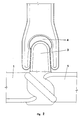
- the coupling between shaft and paddle hub is realized through a propeller provided with a center pin facing up 10, having an elliptic or oval shape in cross section, which can be inserted in the stirrer shaft also through an elliptic or oval connection (cavity) at the lower end 9 of the same.
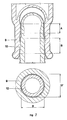
- the center pin can also show a first part A (in fig. 7) having cylindrical shape and oval cross section and a second part B having conical shape and circular cross-section.
- the lower end 9 of the stirrer shaft is bell shaped and machined inside to an elliptic or oval (fig. 6) or in part to a conical circular shape (fig. 7 section A).
- the difference between the maximum D and the minimum D′ axis in the elliptic or oval cross section can be of little value for instance between 6% and 10%.
- the paddles can form a single piece with the hub or the single paddles can be detachably inserted in the central hub which, on its turn, is fixed at the end of the stirrer shaft.
- the connections between paddles and hub are performed through frusto-conical junctions and forced insertion as described above and represented in figures 3,4, the connections between hub and shaft being made through said elliptic or oval or mixed elliptic and conical circular junctions.
- the central hub may be ring shaped with an elliptic or oval or mixed elliptic-conical central hole, in which the stirrer shaft is inserted.
- the hub may show along its outside circumference frusto-conical cavities 6 (fig. 4 and 3 right side), for inserting the stems of the radially arranged paddles, or it can show radially distributed pins 7 on which each single paddle provided with a suitable frusto-conical cavity can be inserted (fig. 3 and 4 left side).
- the cavities as well as the pins on the paddle bearing hub may be arranged in one or more layers, in other words on a single horizontal plane or on more planes at different levels.
- the paddle/shaft and hub/shaft connections take place on surfaces accurately machined to obtain perfectly adapted contact surfaces.
- the detachable paddle stirrers of the present invention in the various construction forms described above, show, with respect to the stirrer of the Sybron patent USP 4.221.488 , the advantage of not requiring in the assembling the use of cryogenic fluids or of thermal devices which may complicate the operation, while the machining of the parts does not require the extreme precision required in the case of the Sybron stirrer (precision which must be the higher, the lower the difference in temperature obtained in the assembling step). Furthermore, disassembly of single blades or of the hub is possible with the aid of a simple mechanical extraction device, while disassembling the hub of the Sybron stirrer is a complex operation based on the possibility of obtaining a high difference of temperature between two pieces in close contact with each other.
- the ones according to the present invention show the advantage that the hub holding the paddles is a separate element which is introduced inside the reaction vessel through a manhole, and then inserted on the shaft when assembling the paddles; as a consequence, the shaft, which is mounted inserting it through the central hole (usually of small diameter), may be sufficiently long to reach near the bottom of the vessel.
- the hub attached to the shaft according to the De Dietrich patent cannot usually be inserted through the central hole (which is too small) and it is therefore necessary to insert the shaft with attached hub through the side manhole; obviously, in this case the shaft should not be too long (total length equal to the distance between manhole and bottom of the vessel).
- the equipment for assembling the paddle holding hub or of the single paddles, according to the present invention is very simple and of a conventional type.
- Suitable swellings on the shaft allow to block the collar.
Landscapes
- Chemical & Material Sciences (AREA)
- Chemical Kinetics & Catalysis (AREA)
- Organic Chemistry (AREA)
- Accessories For Mixers (AREA)
- Mixers Of The Rotary Stirring Type (AREA)
- Food-Manufacturing Devices (AREA)
Applications Claiming Priority (4)
| Application Number | Priority Date | Filing Date | Title |
|---|---|---|---|
| IT8920174A IT1229277B (it) | 1989-04-17 | 1989-04-17 | Agitatore completamente smaltato a pale smontabili fissate all'albero con accoppiamento slamto su slamto, senza guarnizioni. |
| IT2017489 | 1989-04-17 | ||
| IT8921469A IT1231100B (it) | 1989-08-07 | 1989-08-07 | Agitatore completamente smaltato a pale smontabili fissate all'albero con accoppiamento smaltato su smalto, senza guarnizioni. |
| IT2146989 | 1989-08-07 |
Publications (2)
| Publication Number | Publication Date |
|---|---|
| EP0393516A1 true EP0393516A1 (de) | 1990-10-24 |
| EP0393516B1 EP0393516B1 (de) | 1994-09-21 |
Family
ID=26327424
Family Applications (1)
| Application Number | Title | Priority Date | Filing Date |
|---|---|---|---|
| EP90107045A Expired - Lifetime EP0393516B1 (de) | 1989-04-17 | 1990-04-12 | Emailrührer mit von einem Schaft abnehmbarer Schaufeln mit Email-Email-Kupplung ohne Dichtung |
Country Status (3)
| Country | Link |
|---|---|
| EP (1) | EP0393516B1 (de) |
| AT (1) | ATE111766T1 (de) |
| DE (1) | DE69012632T2 (de) |
Cited By (3)
| Publication number | Priority date | Publication date | Assignee | Title |
|---|---|---|---|---|
| EP0495133A1 (de) * | 1991-01-12 | 1992-07-22 | Pfaudler Werke GmbH | Korrosionsgeschützter Rührer mit einer abnehmbaren Rührflügeleinheit |
| DE4325801A1 (de) * | 1993-07-31 | 1993-12-16 | Thale Eisen Huettenwerk | Kraftschlüssige Hohlwelle - in Nabe-Verbindung |
| DE4420570A1 (de) * | 1994-04-02 | 1995-10-05 | Thale Eisen Huettenwerk | Rührer mit Welle und Rührflügeleinrichtung |
Citations (3)
| Publication number | Priority date | Publication date | Assignee | Title |
|---|---|---|---|---|
| US2852238A (en) * | 1957-08-19 | 1958-09-16 | Toms River Cincinnati Chemical | Agitator for lined pressure vessel |
| EP0145370A2 (de) * | 1983-11-21 | 1985-06-19 | De Dietrich (USA), Inc. | Rührwerk mit einer einen Pressitz aufweisenden Rührflügelanordnung |
| US4628574A (en) * | 1983-09-22 | 1986-12-16 | De Dietrich (Usa), Inc. | Method for constructing an impeller assembly and shaft having interference fit |
-
1990
- 1990-04-12 AT AT90107045T patent/ATE111766T1/de not_active IP Right Cessation
- 1990-04-12 DE DE69012632T patent/DE69012632T2/de not_active Expired - Fee Related
- 1990-04-12 EP EP90107045A patent/EP0393516B1/de not_active Expired - Lifetime
Patent Citations (3)
| Publication number | Priority date | Publication date | Assignee | Title |
|---|---|---|---|---|
| US2852238A (en) * | 1957-08-19 | 1958-09-16 | Toms River Cincinnati Chemical | Agitator for lined pressure vessel |
| US4628574A (en) * | 1983-09-22 | 1986-12-16 | De Dietrich (Usa), Inc. | Method for constructing an impeller assembly and shaft having interference fit |
| EP0145370A2 (de) * | 1983-11-21 | 1985-06-19 | De Dietrich (USA), Inc. | Rührwerk mit einer einen Pressitz aufweisenden Rührflügelanordnung |
Cited By (3)
| Publication number | Priority date | Publication date | Assignee | Title |
|---|---|---|---|---|
| EP0495133A1 (de) * | 1991-01-12 | 1992-07-22 | Pfaudler Werke GmbH | Korrosionsgeschützter Rührer mit einer abnehmbaren Rührflügeleinheit |
| DE4325801A1 (de) * | 1993-07-31 | 1993-12-16 | Thale Eisen Huettenwerk | Kraftschlüssige Hohlwelle - in Nabe-Verbindung |
| DE4420570A1 (de) * | 1994-04-02 | 1995-10-05 | Thale Eisen Huettenwerk | Rührer mit Welle und Rührflügeleinrichtung |
Also Published As
| Publication number | Publication date |
|---|---|
| EP0393516B1 (de) | 1994-09-21 |
| ATE111766T1 (de) | 1994-10-15 |
| DE69012632T2 (de) | 1995-01-26 |
| DE69012632D1 (de) | 1994-10-27 |
Similar Documents
| Publication | Publication Date | Title |
|---|---|---|
| US5779449A (en) | Separable, multipartite impeller assembly for centrifugal pumps | |
| US4601583A (en) | Multi-hubbed separable blade agitators | |
| EP0492604A2 (de) | Pumpenzwischengehäuse in Blechbauweise | |
| EP0393516B1 (de) | Emailrührer mit von einem Schaft abnehmbarer Schaufeln mit Email-Email-Kupplung ohne Dichtung | |
| US20020006332A1 (en) | Device and method for detachably connecting an impeller to a pinion shaft in a high speed fluid compressor | |
| US4473171A (en) | Nozzle construction for jacketed pressure vessels | |
| US5286107A (en) | Enamel coated stirrer with paddles detachably fixed on the shaft in enamel to enamel coupling without any gasket | |
| US4628574A (en) | Method for constructing an impeller assembly and shaft having interference fit | |
| EP0492575B1 (de) | Zwischenstufengehäuse für eine Pumpe aus Metallblech und Verfahren zu dessen Herstellung | |
| US6616412B2 (en) | Tapered polygon coupling | |
| WO1985002131A1 (en) | Agitator including impeller assembly and shaft having interference fit | |
| EP0975880B1 (de) | Vorrichtung zur verriegelung eines mechanischen elementes an einer welle | |
| CA2158875A1 (en) | Connection Verifier for a Quick Connector Coupling | |
| US5480252A (en) | Coupling mechanism for quickly axially aligning rotor to journals | |
| US4855103A (en) | Method for manufacturing metallic products from powder by hot isostatic pressing using ceramic cores | |
| EP1222397B1 (de) | Lösbare befestigungsvorrichtung und -verfahren für laufradbefestigung auf eine welle eines hochgeschwindigkeitsverdichters | |
| US4477227A (en) | Keying for shrunk-on turbine wheels | |
| US4738151A (en) | Pinion coupling | |
| US5141350A (en) | Pressurized drive coupling | |
| JP4000504B2 (ja) | 電磁流量計 | |
| CN1009026B (zh) | U形接头 | |
| WO2001083096A1 (en) | Hub assembly | |
| CN213637448U (zh) | 一种液压永磁耦合器 | |
| GB2059518A (en) | Ball bushings | |
| US7338381B2 (en) | Spider and universal joint arrangement |
Legal Events
| Date | Code | Title | Description |
|---|---|---|---|
| PUAI | Public reference made under article 153(3) epc to a published international application that has entered the european phase |
Free format text: ORIGINAL CODE: 0009012 |
|
| AK | Designated contracting states |
Kind code of ref document: A1 Designated state(s): AT BE CH DE FR GB IT LI NL SE |
|
| 17P | Request for examination filed |
Effective date: 19910418 |
|
| 17Q | First examination report despatched |
Effective date: 19920831 |
|
| GRAA | (expected) grant |
Free format text: ORIGINAL CODE: 0009210 |
|
| AK | Designated contracting states |
Kind code of ref document: B1 Designated state(s): AT BE CH DE FR GB IT LI NL SE |
|
| PG25 | Lapsed in a contracting state [announced via postgrant information from national office to epo] |
Ref country code: NL Effective date: 19940921 Ref country code: BE Effective date: 19940921 Ref country code: AT Effective date: 19940921 |
|
| REF | Corresponds to: |
Ref document number: 111766 Country of ref document: AT Date of ref document: 19941015 Kind code of ref document: T |
|
| REF | Corresponds to: |
Ref document number: 69012632 Country of ref document: DE Date of ref document: 19941027 |
|
| ITF | It: translation for a ep patent filed | ||
| ET | Fr: translation filed | ||
| PG25 | Lapsed in a contracting state [announced via postgrant information from national office to epo] |
Ref country code: SE Effective date: 19941221 |
|
| NLV1 | Nl: lapsed or annulled due to failure to fulfill the requirements of art. 29p and 29m of the patents act | ||
| PLBE | No opposition filed within time limit |
Free format text: ORIGINAL CODE: 0009261 |
|
| STAA | Information on the status of an ep patent application or granted ep patent |
Free format text: STATUS: NO OPPOSITION FILED WITHIN TIME LIMIT |
|
| 26N | No opposition filed | ||
| PGFP | Annual fee paid to national office [announced via postgrant information from national office to epo] |
Ref country code: GB Payment date: 19980313 Year of fee payment: 9 |
|
| PGFP | Annual fee paid to national office [announced via postgrant information from national office to epo] |
Ref country code: CH Payment date: 19980324 Year of fee payment: 9 |
|
| PGFP | Annual fee paid to national office [announced via postgrant information from national office to epo] |
Ref country code: FR Payment date: 19980327 Year of fee payment: 9 |
|
| PGFP | Annual fee paid to national office [announced via postgrant information from national office to epo] |
Ref country code: DE Payment date: 19980406 Year of fee payment: 9 |
|
| PG25 | Lapsed in a contracting state [announced via postgrant information from national office to epo] |
Ref country code: GB Free format text: LAPSE BECAUSE OF NON-PAYMENT OF DUE FEES Effective date: 19990412 |
|
| PG25 | Lapsed in a contracting state [announced via postgrant information from national office to epo] |
Ref country code: LI Free format text: LAPSE BECAUSE OF NON-PAYMENT OF DUE FEES Effective date: 19990430 Ref country code: CH Free format text: LAPSE BECAUSE OF NON-PAYMENT OF DUE FEES Effective date: 19990430 |
|
| GBPC | Gb: european patent ceased through non-payment of renewal fee |
Effective date: 19990412 |
|
| REG | Reference to a national code |
Ref country code: CH Ref legal event code: PL |
|
| PG25 | Lapsed in a contracting state [announced via postgrant information from national office to epo] |
Ref country code: FR Free format text: LAPSE BECAUSE OF NON-PAYMENT OF DUE FEES Effective date: 19991231 |
|
| REG | Reference to a national code |
Ref country code: FR Ref legal event code: ST |
|
| PG25 | Lapsed in a contracting state [announced via postgrant information from national office to epo] |
Ref country code: DE Free format text: LAPSE BECAUSE OF NON-PAYMENT OF DUE FEES Effective date: 20000201 |
|
| PG25 | Lapsed in a contracting state [announced via postgrant information from national office to epo] |
Ref country code: IT Free format text: LAPSE BECAUSE OF NON-PAYMENT OF DUE FEES;WARNING: LAPSES OF ITALIAN PATENTS WITH EFFECTIVE DATE BEFORE 2007 MAY HAVE OCCURRED AT ANY TIME BEFORE 2007. THE CORRECT EFFECTIVE DATE MAY BE DIFFERENT FROM THE ONE RECORDED. Effective date: 20050412 |