EP0393576A2 - Milieux d'enregistrement d'information - Google Patents
Milieux d'enregistrement d'information Download PDFInfo
- Publication number
- EP0393576A2 EP0393576A2 EP90107247A EP90107247A EP0393576A2 EP 0393576 A2 EP0393576 A2 EP 0393576A2 EP 90107247 A EP90107247 A EP 90107247A EP 90107247 A EP90107247 A EP 90107247A EP 0393576 A2 EP0393576 A2 EP 0393576A2
- Authority
- EP
- European Patent Office
- Prior art keywords
- atom
- metallic layer
- hafnium
- layer
- information recording
- Prior art date
- Legal status (The legal status is an assumption and is not a legal conclusion. Google has not performed a legal analysis and makes no representation as to the accuracy of the status listed.)
- Granted
Links
Images
Classifications
-
- G—PHYSICS
- G11—INFORMATION STORAGE
- G11B—INFORMATION STORAGE BASED ON RELATIVE MOVEMENT BETWEEN RECORD CARRIER AND TRANSDUCER
- G11B11/00—Recording on or reproducing from the same record carrier wherein for these two operations the methods are covered by different main groups of groups G11B3/00 - G11B7/00 or by different subgroups of group G11B9/00; Record carriers therefor
- G11B11/10—Recording on or reproducing from the same record carrier wherein for these two operations the methods are covered by different main groups of groups G11B3/00 - G11B7/00 or by different subgroups of group G11B9/00; Record carriers therefor using recording by magnetic means or other means for magnetisation or demagnetisation of a record carrier, e.g. light induced spin magnetisation; Demagnetisation by thermal or stress means in the presence or not of an orienting magnetic field
- G11B11/105—Recording on or reproducing from the same record carrier wherein for these two operations the methods are covered by different main groups of groups G11B3/00 - G11B7/00 or by different subgroups of group G11B9/00; Record carriers therefor using recording by magnetic means or other means for magnetisation or demagnetisation of a record carrier, e.g. light induced spin magnetisation; Demagnetisation by thermal or stress means in the presence or not of an orienting magnetic field using a beam of light or a magnetic field for recording by change of magnetisation and a beam of light for reproducing, i.e. magneto-optical, e.g. light-induced thermomagnetic recording, spin magnetisation recording, Kerr or Faraday effect reproducing
- G11B11/10582—Record carriers characterised by the selection of the material or by the structure or form
- G11B11/10586—Record carriers characterised by the selection of the material or by the structure or form characterised by the selection of the material
-
- G—PHYSICS
- G11—INFORMATION STORAGE
- G11B—INFORMATION STORAGE BASED ON RELATIVE MOVEMENT BETWEEN RECORD CARRIER AND TRANSDUCER
- G11B5/00—Recording by magnetisation or demagnetisation of a record carrier; Reproducing by magnetic means; Record carriers therefor
- G11B5/62—Record carriers characterised by the selection of the material
- G11B5/64—Record carriers characterised by the selection of the material comprising only the magnetic material without bonding agent
- G11B5/66—Record carriers characterised by the selection of the material comprising only the magnetic material without bonding agent the record carriers consisting of several layers
-
- G—PHYSICS
- G11—INFORMATION STORAGE
- G11B—INFORMATION STORAGE BASED ON RELATIVE MOVEMENT BETWEEN RECORD CARRIER AND TRANSDUCER
- G11B7/00—Recording or reproducing by optical means, e.g. recording using a thermal beam of optical radiation by modifying optical properties or the physical structure, reproducing using an optical beam at lower power by sensing optical properties; Record carriers therefor
- G11B7/24—Record carriers characterised by shape, structure or physical properties, or by the selection of the material
- G11B7/241—Record carriers characterised by shape, structure or physical properties, or by the selection of the material characterised by the selection of the material
- G11B7/252—Record carriers characterised by shape, structure or physical properties, or by the selection of the material characterised by the selection of the material of layers other than recording layers
-
- G—PHYSICS
- G11—INFORMATION STORAGE
- G11B—INFORMATION STORAGE BASED ON RELATIVE MOVEMENT BETWEEN RECORD CARRIER AND TRANSDUCER
- G11B7/00—Recording or reproducing by optical means, e.g. recording using a thermal beam of optical radiation by modifying optical properties or the physical structure, reproducing using an optical beam at lower power by sensing optical properties; Record carriers therefor
- G11B7/24—Record carriers characterised by shape, structure or physical properties, or by the selection of the material
- G11B7/241—Record carriers characterised by shape, structure or physical properties, or by the selection of the material characterised by the selection of the material
- G11B7/242—Record carriers characterised by shape, structure or physical properties, or by the selection of the material characterised by the selection of the material of recording layers
- G11B7/243—Record carriers characterised by shape, structure or physical properties, or by the selection of the material characterised by the selection of the material of recording layers comprising inorganic materials only, e.g. ablative layers
- G11B2007/24302—Metals or metalloids
- G11B2007/24304—Metals or metalloids group 2 or 12 elements (e.g. Be, Ca, Mg, Zn, Cd)
-
- G—PHYSICS
- G11—INFORMATION STORAGE
- G11B—INFORMATION STORAGE BASED ON RELATIVE MOVEMENT BETWEEN RECORD CARRIER AND TRANSDUCER
- G11B7/00—Recording or reproducing by optical means, e.g. recording using a thermal beam of optical radiation by modifying optical properties or the physical structure, reproducing using an optical beam at lower power by sensing optical properties; Record carriers therefor
- G11B7/24—Record carriers characterised by shape, structure or physical properties, or by the selection of the material
- G11B7/241—Record carriers characterised by shape, structure or physical properties, or by the selection of the material characterised by the selection of the material
- G11B7/242—Record carriers characterised by shape, structure or physical properties, or by the selection of the material characterised by the selection of the material of recording layers
- G11B7/243—Record carriers characterised by shape, structure or physical properties, or by the selection of the material characterised by the selection of the material of recording layers comprising inorganic materials only, e.g. ablative layers
- G11B7/2433—Metals or elements of Groups 13, 14, 15 or 16 of the Periodic Table, e.g. B, Si, Ge, As, Sb, Bi, Se or Te
-
- G—PHYSICS
- G11—INFORMATION STORAGE
- G11B—INFORMATION STORAGE BASED ON RELATIVE MOVEMENT BETWEEN RECORD CARRIER AND TRANSDUCER
- G11B7/00—Recording or reproducing by optical means, e.g. recording using a thermal beam of optical radiation by modifying optical properties or the physical structure, reproducing using an optical beam at lower power by sensing optical properties; Record carriers therefor
- G11B7/24—Record carriers characterised by shape, structure or physical properties, or by the selection of the material
- G11B7/241—Record carriers characterised by shape, structure or physical properties, or by the selection of the material characterised by the selection of the material
- G11B7/252—Record carriers characterised by shape, structure or physical properties, or by the selection of the material characterised by the selection of the material of layers other than recording layers
- G11B7/253—Record carriers characterised by shape, structure or physical properties, or by the selection of the material characterised by the selection of the material of layers other than recording layers of substrates
- G11B7/2531—Record carriers characterised by shape, structure or physical properties, or by the selection of the material characterised by the selection of the material of layers other than recording layers of substrates comprising glass
-
- G—PHYSICS
- G11—INFORMATION STORAGE
- G11B—INFORMATION STORAGE BASED ON RELATIVE MOVEMENT BETWEEN RECORD CARRIER AND TRANSDUCER
- G11B7/00—Recording or reproducing by optical means, e.g. recording using a thermal beam of optical radiation by modifying optical properties or the physical structure, reproducing using an optical beam at lower power by sensing optical properties; Record carriers therefor
- G11B7/24—Record carriers characterised by shape, structure or physical properties, or by the selection of the material
- G11B7/241—Record carriers characterised by shape, structure or physical properties, or by the selection of the material characterised by the selection of the material
- G11B7/252—Record carriers characterised by shape, structure or physical properties, or by the selection of the material characterised by the selection of the material of layers other than recording layers
- G11B7/253—Record carriers characterised by shape, structure or physical properties, or by the selection of the material characterised by the selection of the material of layers other than recording layers of substrates
- G11B7/2532—Record carriers characterised by shape, structure or physical properties, or by the selection of the material characterised by the selection of the material of layers other than recording layers of substrates comprising metals
-
- G—PHYSICS
- G11—INFORMATION STORAGE
- G11B—INFORMATION STORAGE BASED ON RELATIVE MOVEMENT BETWEEN RECORD CARRIER AND TRANSDUCER
- G11B7/00—Recording or reproducing by optical means, e.g. recording using a thermal beam of optical radiation by modifying optical properties or the physical structure, reproducing using an optical beam at lower power by sensing optical properties; Record carriers therefor
- G11B7/24—Record carriers characterised by shape, structure or physical properties, or by the selection of the material
- G11B7/241—Record carriers characterised by shape, structure or physical properties, or by the selection of the material characterised by the selection of the material
- G11B7/252—Record carriers characterised by shape, structure or physical properties, or by the selection of the material characterised by the selection of the material of layers other than recording layers
- G11B7/253—Record carriers characterised by shape, structure or physical properties, or by the selection of the material characterised by the selection of the material of layers other than recording layers of substrates
- G11B7/2533—Record carriers characterised by shape, structure or physical properties, or by the selection of the material characterised by the selection of the material of layers other than recording layers of substrates comprising resins
-
- G—PHYSICS
- G11—INFORMATION STORAGE
- G11B—INFORMATION STORAGE BASED ON RELATIVE MOVEMENT BETWEEN RECORD CARRIER AND TRANSDUCER
- G11B7/00—Recording or reproducing by optical means, e.g. recording using a thermal beam of optical radiation by modifying optical properties or the physical structure, reproducing using an optical beam at lower power by sensing optical properties; Record carriers therefor
- G11B7/24—Record carriers characterised by shape, structure or physical properties, or by the selection of the material
- G11B7/241—Record carriers characterised by shape, structure or physical properties, or by the selection of the material characterised by the selection of the material
- G11B7/252—Record carriers characterised by shape, structure or physical properties, or by the selection of the material characterised by the selection of the material of layers other than recording layers
- G11B7/253—Record carriers characterised by shape, structure or physical properties, or by the selection of the material characterised by the selection of the material of layers other than recording layers of substrates
- G11B7/2533—Record carriers characterised by shape, structure or physical properties, or by the selection of the material characterised by the selection of the material of layers other than recording layers of substrates comprising resins
- G11B7/2534—Record carriers characterised by shape, structure or physical properties, or by the selection of the material characterised by the selection of the material of layers other than recording layers of substrates comprising resins polycarbonates [PC]
-
- G—PHYSICS
- G11—INFORMATION STORAGE
- G11B—INFORMATION STORAGE BASED ON RELATIVE MOVEMENT BETWEEN RECORD CARRIER AND TRANSDUCER
- G11B7/00—Recording or reproducing by optical means, e.g. recording using a thermal beam of optical radiation by modifying optical properties or the physical structure, reproducing using an optical beam at lower power by sensing optical properties; Record carriers therefor
- G11B7/24—Record carriers characterised by shape, structure or physical properties, or by the selection of the material
- G11B7/241—Record carriers characterised by shape, structure or physical properties, or by the selection of the material characterised by the selection of the material
- G11B7/252—Record carriers characterised by shape, structure or physical properties, or by the selection of the material characterised by the selection of the material of layers other than recording layers
- G11B7/253—Record carriers characterised by shape, structure or physical properties, or by the selection of the material characterised by the selection of the material of layers other than recording layers of substrates
- G11B7/2533—Record carriers characterised by shape, structure or physical properties, or by the selection of the material characterised by the selection of the material of layers other than recording layers of substrates comprising resins
- G11B7/2538—Record carriers characterised by shape, structure or physical properties, or by the selection of the material characterised by the selection of the material of layers other than recording layers of substrates comprising resins polycycloolefins [PCO]
-
- G—PHYSICS
- G11—INFORMATION STORAGE
- G11B—INFORMATION STORAGE BASED ON RELATIVE MOVEMENT BETWEEN RECORD CARRIER AND TRANSDUCER
- G11B7/00—Recording or reproducing by optical means, e.g. recording using a thermal beam of optical radiation by modifying optical properties or the physical structure, reproducing using an optical beam at lower power by sensing optical properties; Record carriers therefor
- G11B7/24—Record carriers characterised by shape, structure or physical properties, or by the selection of the material
- G11B7/241—Record carriers characterised by shape, structure or physical properties, or by the selection of the material characterised by the selection of the material
- G11B7/252—Record carriers characterised by shape, structure or physical properties, or by the selection of the material characterised by the selection of the material of layers other than recording layers
- G11B7/257—Record carriers characterised by shape, structure or physical properties, or by the selection of the material characterised by the selection of the material of layers other than recording layers of layers having properties involved in recording or reproduction, e.g. optical interference layers or sensitising layers or dielectric layers, which are protecting the recording layers
- G11B7/2578—Record carriers characterised by shape, structure or physical properties, or by the selection of the material characterised by the selection of the material of layers other than recording layers of layers having properties involved in recording or reproduction, e.g. optical interference layers or sensitising layers or dielectric layers, which are protecting the recording layers consisting essentially of inorganic materials
-
- G—PHYSICS
- G11—INFORMATION STORAGE
- G11B—INFORMATION STORAGE BASED ON RELATIVE MOVEMENT BETWEEN RECORD CARRIER AND TRANSDUCER
- G11B7/00—Recording or reproducing by optical means, e.g. recording using a thermal beam of optical radiation by modifying optical properties or the physical structure, reproducing using an optical beam at lower power by sensing optical properties; Record carriers therefor
- G11B7/24—Record carriers characterised by shape, structure or physical properties, or by the selection of the material
- G11B7/241—Record carriers characterised by shape, structure or physical properties, or by the selection of the material characterised by the selection of the material
- G11B7/252—Record carriers characterised by shape, structure or physical properties, or by the selection of the material characterised by the selection of the material of layers other than recording layers
- G11B7/258—Record carriers characterised by shape, structure or physical properties, or by the selection of the material characterised by the selection of the material of layers other than recording layers of reflective layers
- G11B7/2585—Record carriers characterised by shape, structure or physical properties, or by the selection of the material characterised by the selection of the material of layers other than recording layers of reflective layers based on aluminium
-
- Y—GENERAL TAGGING OF NEW TECHNOLOGICAL DEVELOPMENTS; GENERAL TAGGING OF CROSS-SECTIONAL TECHNOLOGIES SPANNING OVER SEVERAL SECTIONS OF THE IPC; TECHNICAL SUBJECTS COVERED BY FORMER USPC CROSS-REFERENCE ART COLLECTIONS [XRACs] AND DIGESTS
- Y10—TECHNICAL SUBJECTS COVERED BY FORMER USPC
- Y10S—TECHNICAL SUBJECTS COVERED BY FORMER USPC CROSS-REFERENCE ART COLLECTIONS [XRACs] AND DIGESTS
- Y10S428/00—Stock material or miscellaneous articles
- Y10S428/90—Magnetic feature
-
- Y—GENERAL TAGGING OF NEW TECHNOLOGICAL DEVELOPMENTS; GENERAL TAGGING OF CROSS-SECTIONAL TECHNOLOGIES SPANNING OVER SEVERAL SECTIONS OF THE IPC; TECHNICAL SUBJECTS COVERED BY FORMER USPC CROSS-REFERENCE ART COLLECTIONS [XRACs] AND DIGESTS
- Y10—TECHNICAL SUBJECTS COVERED BY FORMER USPC
- Y10S—TECHNICAL SUBJECTS COVERED BY FORMER USPC CROSS-REFERENCE ART COLLECTIONS [XRACs] AND DIGESTS
- Y10S428/00—Stock material or miscellaneous articles
- Y10S428/922—Static electricity metal bleed-off metallic stock
- Y10S428/9265—Special properties
- Y10S428/928—Magnetic property
-
- Y—GENERAL TAGGING OF NEW TECHNOLOGICAL DEVELOPMENTS; GENERAL TAGGING OF CROSS-SECTIONAL TECHNOLOGIES SPANNING OVER SEVERAL SECTIONS OF THE IPC; TECHNICAL SUBJECTS COVERED BY FORMER USPC CROSS-REFERENCE ART COLLECTIONS [XRACs] AND DIGESTS
- Y10—TECHNICAL SUBJECTS COVERED BY FORMER USPC
- Y10T—TECHNICAL SUBJECTS COVERED BY FORMER US CLASSIFICATION
- Y10T428/00—Stock material or miscellaneous articles
- Y10T428/12—All metal or with adjacent metals
- Y10T428/12493—Composite; i.e., plural, adjacent, spatially distinct metal components [e.g., layers, joint, etc.]
- Y10T428/12736—Al-base component
-
- Y—GENERAL TAGGING OF NEW TECHNOLOGICAL DEVELOPMENTS; GENERAL TAGGING OF CROSS-SECTIONAL TECHNOLOGIES SPANNING OVER SEVERAL SECTIONS OF THE IPC; TECHNICAL SUBJECTS COVERED BY FORMER USPC CROSS-REFERENCE ART COLLECTIONS [XRACs] AND DIGESTS
- Y10—TECHNICAL SUBJECTS COVERED BY FORMER USPC
- Y10T—TECHNICAL SUBJECTS COVERED BY FORMER US CLASSIFICATION
- Y10T428/00—Stock material or miscellaneous articles
- Y10T428/12—All metal or with adjacent metals
- Y10T428/12493—Composite; i.e., plural, adjacent, spatially distinct metal components [e.g., layers, joint, etc.]
- Y10T428/12736—Al-base component
- Y10T428/12743—Next to refractory [Group IVB, VB, or VIB] metal-base component
Definitions
- This invention relates to information recording media having a metallic layer and more particularly to information recording media excellent in corrosion resistance or stability, and small in dependence of their recording power on linear velocity.
- information recording media such as magnetooptical recording discs comprising a substrate and thereon a recording layer and a metallic layer and capable of rewriting information
- dependence of the recording power on linear velocity is made small so that the recording power for recording information in said media does not largely vary with the inner peripheral and outer peripheral portions of the medium.
- a metallic layer is formed, in addition to a magnetooptical recording layer, on a substrate.
- the metallic layers which have been used so far in the information recording media of the type such as magnetooptical recording discs are composed of nickel alloys, aluminum metal or aluminum alloys containing 0.1- 10% by weight of titanium.
- the metallic layers composed of aluminum metal or aluminum-titanium alloys had such a disadvantage that they are poor in corrosion resistance and cannot withstand a long term-service.
- the metallic layers composed of nickel alloys had also such a serious disadvantage that the recording power required at the time of writing information in the information recording medium largely varies with the inner peripheral and outer peripheral portions of said medium, and thus the dependence of the recording power on linear velocity is still large.
- the present inventors prosecuted extensive researches to find that the information recording media having a metallic layer composed of an aluminum alloy containing at least hafnium are excellent in corrosion resistance and small in dependence of the recording power on linear velocity.
- the present invention has been accomplished.
- the present invention is intended to solve such problems associated with the prior art as mentioned above, and an object of the invention is to provide information recording media which are excellent in corrosion resistance and small in dependence of the recording power on linear velocity.
- the first information recording medium of the present invention which has a recording layer and a metallic layer on a substrate is characterized in that the metallic layer is composed of an aluminum alloy containing at least one element selected from among hafnium (Hf) and niobium (Nb) in an amount of 0.1-10 atom% based on all atoms constituting aluminum alloy layer.
- Hf hafnium
- Nb niobium
- the second information recording medium of the invention which has a recording layer and a metallic layer on a substrate is characterized in that the metallic layer is composed of an aluminum alloy containing 0.1-9.5 atom% of hafnium and 0.1-5 atom% of chromium based on all atoms constituting aluminum alloy layer, the combined content of said hafnium and chromium being less than 10 atom%.
- the third information recording medium of the invention which has a recording layer and a metallic layer on a substrate is characterized in that the metallic layer is composed of an aluminum alloy containing 0.1-9.5 atom% of hafnium, 0.1-5 atom% of chromium and 0.1-9.5 atom% of titanium based on all atoms constituting aluminum alloy layers the combined content of said hafnium, chromium and titanium being less than 10 atom%.
- the fourth information recording medium of the invention which has a recording layer and a metallic layer on a substrate is characterized in that the metallic layer is composed of an aluminum alloy containing 0.5-5 atom% of hafnium and 0.5-5 atom% of titanium based on all atoms constituting aluminum alloy layer, the combined content of said hafnium and titanium being 1-5.5 atom%.
- the fifth information recording medium of the invention which has a recording layer and a metallic layer on a substrate is characterized in that the metallic layer is composed of an aluminum alloy containing 0.1-10 atom% of hafnium and 0.1-10 atom% of magnesium based on all atoms constituting aluminum alloy layer, the combined content of said hafnium and magnesium being less than 15 atom%.
- the sixth information recording medium of the invention which has a recording layer and a metallic layer on a substrate is characterized in that the metallic layer is composed of an aluminum alloy containing 0.1-10 atom% of hafnium, 0.1-10 atom% of magnesium and 0.1-10 atom% of titanium based on all atoms constituting aluminum alloy layer, the combined content of said hafnium, magnesium and titanium being less than 15 atom%.
- the seventh information recording medium of the invention which has a recording layer and a metallic layer on a substrate is characterized in that the metallic layer is composed of an aluminum alloy containing 0.1-10 atom% of hafnium, 0.1-10 atom% of magnesium and not more than 10 atom% of chromium based on all atoms constituting aluminum alloy layer, the combined content of said hafnium, magnesium and chromium being less than 15 atom%.
- the eighth information recording medium of the invention which has a recording layer and a metallic layer on a substrate is characterized in that the metallic layer is composed of an aluminum alloy containing 0.1-10 atom% of hafnium, 0.1-10 atom% of magnesium, 0.1-10 atom% of titanium and less than 10 atom% of chromium based on all atoms constituting aluminum alloy layers the combined content of said hafnium, magnesium, titanium and chromium being less than 15 atom%.
- the information recording media of the present invention are illustrated below in detail.
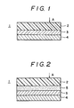
- Fig. 1 is a rough sketch of the information recording medium in cross section of one embodiment of the invention
- Fig. 2 is also a rough sketch of the information recording medium in cross section of another embodiment of the invention.
- information recording media of the invention the information stored in said recording media is read out by means of light such as laser beam.
- Information recording media of this type include, in concrete, postscript type optical disc capable of additional recording but incapable of erasing information recorded, rewriting type optical discs such as magnetooptical recording discs and phase change discs, capable of recording information as well as of erasing and reproducing the information recorded.
- a recording layer 3 and a metallic layer 4 are formed on a substrate 2 in that order.
- Materials for the above-mentioned substrate 2 used in the invention are not particularly limited to specific ones. However, when laser beam is incident upon the substrate 2 (from the direction of an arrow A), the materials used therefor are preferably those which are transparent. Besides inorganic materials such as glass, aluminum and the like, such transparent materials include, for example, organic materials such as poly(methyl methacrylate), polycarbonate, polymer alloys of polycarbonate with polystyrene, such cycloolefin random copolymers as disclosed in U.S. Patent No.
- cycloolefin random copolymers (A) such cycloolefin random copolymers (A) as mentioned below, poly-4-methyl-1-pentene, epoxy resins, polyether sulfone, polysulfone, polyether imide and the like. Of these organic materials, preferred are poly(methyl methacrylate), polycarbonate, such cycloolefin random copolymers as disclosed in U.S. Patent No. 4,614,778 and the cycloolefin random copolymers (A) as mentioned below.
- particularly desirable materials for the substrate used in the present invention are cycloolefin random copolymers (A) of ethylene and a cycloolefin represented by the following general formula [I], [I-a] or [I-b].
- n is 0 or a positive integer
- R1 to R12 are the same or different, and each reperesents a hydrogen atom, a halogen atom or a hydrocarbon group and R9 to R12, when taken together, may form a mono- or poly-cyclic hydrocarbon ring which may optionally have double bond or bonds, or R9 and R10 or R11 and R12, when taken together, may form an alkylidene group
- cycloolefin represented by the general formula [I] may also be represented by the following general formula [I-a]
- n is 0 or 1
- m is 0 or positive integer
- R1 to R18 represent each a atom or a group selected from the group of a hydrogen atom, a halogen atom and a hydrocarbon group.
- R15 to R18 when taken together, may form a mono- or poly-cyclic hydrocarbon ring which may optionally have double bond or bonds.
- R15 and R16, or R17 and R18, when taken together, may form an alkylidene group.
- p is an integer of at least 0, q and r are each 0,1 or 2
- R1 to R15 represent each an atom or a group selected from the group of a hydrogen atom, a halogen atom, an aliphatic hydrocarbon group, an aromatic hydrocarbon group and an alkoxy group, and R5 (or R6) and R8 (or R7) may be bonded together directly without an intermediate group or through an alkylene group of one to three carbon atoms.
- the concrete example of the cycloolefins represented by the general formula [I] includes 1,4,5,8-dimethano-1,2,3,4,4a,5,8,8a-octahydronaphthalene, such octahydronaphthalenes as 2-methyl-1,4,5,8-dimethano-1,2,3,4,4a,5,8,8a-octahydronaphthalene, 2-ethyl-1,4,5,8-dimethano-1,2,3,4,4a,5,8,8a-octahydronaphthalene, 2-propyl-1,4,5,8-dimethano-1,2,3,4,4a,5,8,8a-octahydronaphthalene, 2-hexyl-1,4,5,8-dimethano-1,2,3,4,4a,5,8,8a-octahydronaphthalene, 2,3-dimethyl-1,4,5,8-dimethano-1,2,3,4,4a,5,8,8
- the cycloolefin represented by the general formula [I] includes, bicyclo[2,2,1]hepto-2-en derivatives, tetracyclo[4,4,0,1 2.5 ,1 7.10 ]-3-dodecene derivatives, hexacyclo[6,6,1,1 3.6 ,1 10.13 ,0 2.7 ,0 9.14 ]-4- heptadesene, derivaties, octacyclo[8,8,0,1 2.9 ,1 4.7 ,1 11.18 ,1 13.16 ,0 3.8 ,0 12.17 ]-5-docosene derivaties, pentacyclo[8,8,0,1 2.9 ,1 4.7 ,1 11.18 ,1 13.16 ,0 3.8 ,0 12.17 ]-5-docosene derivatives, pentacyclo[6,6,1,1 3.6 ,0 2.7 ,0 9.14 ]-4-hexadecene derivatives, h
- the cycloolefin random copolymers (A) comprise ethylene units and the above-mentioned cycloolefin units as the essential components as aforesaid, however, if necessary, in addition to these two essential components, said copolymers may contain other copolymerizable unsaturated monomer components so long as they will not throw hinderances in the way of accomplishing the object of the present invention.
- the unsaturated monomers which may be copolymerized, if necessary, with the copolymers (A) may include, for example, alpha-olefins having from 3 to 20 carbon atoms such as propylene, 1-butene, 4-methyl-1-pentene, 1-hexene, 1-octene, 1-decene, 1-dodecene, 1-tetradecene, 1-hexadecene, 1-octadecene and 1-eicosene which may be used in an amount of up to an equimolar to the ethylene component unit in the resulting random copolymer.
- alpha-olefins having from 3 to 20 carbon atoms such as propylene, 1-butene, 4-methyl-1-pentene, 1-hexene, 1-octene, 1-decene, 1-dodecene, 1-tetradecene, 1-hexadecene, 1-octadecen
- the recurring units [a] derived from ethylene are present in an amount of from 40 to 85 mol%, preferably from 50 to 75 mol%, while the recurring units [b] derived from the cycloolefin are present in an amount of from 15 to 60 mol%, preferably from 25 to 50 mol%, and these recurring units [a] and [b] are arranged at random in the substantially linear chain of the copolymer [A].
- the molar percentage of the recurring units [a] and [b] were determined by 13C-NMR. The fact that this cycloolefin random copolymer [A] is completely soluble in decalin at 135°C confirms that it is substantially linear and free from a gel-forming crosslinked structure.
- the cycloolefin random copolymer [A] has an intrinsic viscosity [ ⁇ ] of from 0.05 to 10 dl/g, preferably from 0.08 to 5 dl/g as measured in decalin at 135°C.
- the softening temperature (TMA) of the cycloolefin random copolymer [A] as measured by a thermal mechanical analyzer is at least 70°C, preferably from 90 to 250°C, and further preferably from 100 to 200°C.
- the softening temperature (TMA) referred to above was determined by monitoring thermal deformation behavior of a 1 mm sheet of the copolymer [A) using a thermomechanical analyzer manufactured and sold by Du Pont.
- This cycloolefin random copolymer [A] has a glass transition temperature (Tg) of normally from 50° to 230°C, preferably from 70° to 210°C.
- the crystallinity of this cycloolefin random copolymer [A] as measured by X-ray diffractometry is normally from 0 to 10%, preferably from 0 to 7%, and further preferably from 0 to 5%.
- the cycloolefin copolymers (A) constituting the cycloolefin random copolymer composition used in the present invention for forming the substrate may all be prepared by the processes proposed by the present inventors in Japanese Patent L-O-P Publns. Nos. 168708/1985, 120816/1986, 115912/1986 and 115916/1986, 252406/1987, 252407/1987, 271308/1986 and 272216/1986, while suitably selecting the conditions.
- a cycloolefin random copolymer composition comprising a cycloolefin random copolymer [A] prepared by copolymerizing ethylene with a cycloolefin represented by the following formula [I], [I-a] or [I-b] and having an intrinsic viscosity [ ⁇ ] of 0.05-10 dl/g measured in decalin at 135°C and a softening temperature (TMA) of at least 70°C, and a cycloolefin random copolymer [B] prepared by copolymerizing ethylene with a cycloolefin represented by the formula [I], [I-a] or [I-b] and having an intrinsic viscosity [ ⁇ ] of 0.05-5 dl/g measured in decalin at 135°C and a softening temperature (TMA) of less than 70°C.
- a cycloolefin random copolymer composition comprising a cycloolefin random copo
- the substrate of the magnetooptical recording media according to the invention may be made of polymers having recurring units of the general formula [III] resulting from ring opening of the cycloolefin monomers [I], or polymers having recurring units of the general formula [IV] resulting from hydrogenation of the units [III].
- n and R1 to R12 are as defined in the general formula [I].
- a thickness of the substrate is preferably 0.5-5 mm and especially 1-2 mm.
- materials for the recording layer 3 are not particularly limited to specific ones.
- this recording layer 3 is preferably composed of at least one member selected from among (i) 3d transition metals and at least one element selected from among (iii) rare earth elements, or composed of at least one member selected from among (i) 3d transition metals, (ii) a corrosion-resistant metal, and at least one element selected from among (iii) rare earth elements.
- the 3d transition metals used include Fe, Co, Ti, V, Cr, Mn, Ni, Cu and Zn. Of these metals, preferred is Fe or Co, or are both of them.
- the corrosion-resistant metal (ii) is capable of improving oxidation resistance of this magnetooptical recording layer as the recording layer 3 by incorporation into this recording layer 3 of said corrosion-resistant metal.
- Such corrosion-resistant metal used includes Pt, Pd, Ti, Zr, Ta, Mo, Nb and Hf. Of these metals, preferred are Pt, Pd and Ti, and particularly Pt or Pd, or both of them.
- the rate earth elements (iii) used include, for example, Gd, Tb, Dy, Ho, Er, Tm, Yb, Lu, La, Ce, Pr, Nd, Pm, Sm and Eu. Of these elements, preferred are Gd, Tb, Dy, Ho, Nd, Sm and Pr.
- Such magnetooptical recording layer as mentioned above desirably contains the 3d transition metal (i) in an amount of 30-85 atom%, preferably 40-70 atom%, the corrosion-resistant metal (ii) in an amount of less than 30 atom%, preferably 5-25 atom%, and the rare earth element (iii) in an amount of 5-50 atom%, preferably 25-45 atom%.
- this recording layer 3 is composed of such an alloy film, for example, as consisting essentially of Te or Se, and of Te-Ge-Sb alloy film, In-Sb-Te alloy film Te-Ge-Cr alloy film or Te-Ge-Zn alloy film. Further an organic dye film composed of polymethine compounds or cyanine compounds may also be used as the phase change type recording layer.
- a thickness of the recording layer 3, though not particularly limited, is 50-5000 ⁇ , preferably 100-2000 ⁇ .
- the metallic layer is formed from an aluminum alloy containing 0.1-10 atom% of at least one element (metal) selected from among hafnium and niobium.
- the metallic layer 4 is composed of an aluminum alloy containing 0.1-10 atom%, preferably 1-6 atom% of hafnium (Hf), an aluminum alloy containing 0.1-10 atom%, preferably 1-6 atom% of niobium (Nb), or of an aluminum alloy containing both hafnium and niobium in an amount totaling to 0.1-10 atom%.
- Hf hafnium
- Nb niobium
- the metallic layer 4 as mentioned above may contain small amounts of at least one of other metals (elements) in addition to aluminum, hafnium and/or niobium.
- other metal as mentioned above include, for example, chromium (Cr, only in case of Al-Nb alloy), silicon (Si), tantalum (Ta), copper (Cu), tungsten (W), zirconium (Zr), manganese (Mn), magnesium (Mg, only in case of Al-Nb alloy) and vanadium (V).
- the amount of these other metals contained, if any, in the metallic layer is usually less than 5 atom%, preferably less than 2 atom%.
- the metallic layer is formed from an aluminum alloy containing 0.1-9.5 atom%, preferably 1-5 atom% of hafnium and 0.1-5 atom%, preferably 1-3 atom% of chromium.
- the combined content of hafnium and chromium is preferably less than 10 atom%.
- the metallic layer is formed from an aluminum alloy containing 0.1-9.5 atom%, preferably 1-5 atom% of hafnium, 0.-5 atom%, preferably 1-3 atom% of chromium and 0.1-9 5 atom%, preferably 1-5 atom% of titanium.
- the combined content of hafnium, chromium and titanium is preferably less than 10 atom%.
- the metallic layers of the second and third information recording media of the invention as illustrated above may also contain, in addition to the aluminum, hafnium, chromium and titanium, small amounts of at least one of other elements (metals).
- Such other elements (metal) include, for example, silicon (Si), tantalum (Ta), copper (Cu), tungsten (W), zirconium (Zr), manganese (Mn), and vanadium (V).
- the amount of these other elements (metals) contained, if any, in the metallic layer is usually less than 5 atom%, preferably less than 2 atom%.
- the metallic layer is formed from an aluminum alloy containing 0.5-5 atom%, preferably 1-3 atom% of hafnium, and 0.5-5 atom%, preferably 1-3 atom% of titanium.
- the combined content of hafnium and titanium is 1-5.5 atom%, preferably 2-4 atom%.
- the metallic layer of the fourth information recording medium of the invention as illustrated above may also contain, in addition to aluminum, hafnium and titanium, small amounts of at least one of other elements (metals)
- Such other elements (metals) include, for example, silicon (Si), tantalum (Ta), copper (Cu), tungsten (W), zirconium (Zr), manganese (Mn), and vanadium (V).
- the amount of these other elements (metals) contained, if any, in the metallic layer is usually less than 5 atom%, preferably less than 2 atom%.
- the metallic layer is formed from an aluminum alloy containing 0.1-10 atom%, preferably 1-5 atom% of hafnium and 0.1-10 atom%, preferably 1-5 atom% of magnesium
- the combined content of hafnium and magnesium is less than 15 atom%, preferably 1-10 atom%.
- the metallic layer is formed from an aluminum alloy containing 0.1-10 atom%, preferably 1-5 atom% of hafnium, 0.1-10 atom%, preferably 1-5 atom% of magnesium and 0.1-10 atom%, preferably 1-5 atom% of titanium.
- the combined content of hafnium, magnesium and titanium is desirably less than 15 atom%, preferably 1-10 atom%.
- the metallic layer is formed from an aluminum alloy containing 0.1-10 atom%, preferably 1-5 atom% of hafnium, 0.1-10 atom%, preferably 1-5 atom% of magnesium and not more than 10 atom%, preferably 0.1-10 atom%, more preferably 1-5 atom% of chromium.
- the combined content of hafnium, magnesium and chromium is desirably less than 15 atom%, preferably 1-10 atom%.
- the metallic layer is formed from an aluminum alloy containing 0.1-10 atom%, preferably 1-5 atom% of hafnium, 0.1-10 atom%, preferably 1-5 atom% of magnesium, less than 10 atom%, preferably 1-5 atom% of chromium and 0.1-10 atom%, preferably 1-5 atom% of titanium.
- the combined content of hafnium, magnesium, chromium and titanium is desirably less than 15 atom%, preferably 1-10 atom%.
- the metallic layers may each contain small amounts of at least one of other elements (metals) in addition to hafnium, magnesium, titanium and chromium.
- Such small amounts of other elements (metals) include, for example, silicon (Si), tantalum (Ta), copper (Cu), tungsten (W), zirconium (Zr), manganese (Mn) and vanadium (V).
- the amount of such other elements (metals) contained, if any, in the metallic layer is usually less than 5 atom%, preferably less than 2 atom%.
- a thickness of the above-mentioned metallic layers is 100-5000 ⁇ , preferably 500-3000 ⁇ and especially 700-2000 ⁇ .
- the metallic layers used in the present invention fulfil their function as good heat conductive layers, and in the presence of these metallic layers, the center portion of pits formed in the recording layers may be prevented from being excessively heated to high temperature by the action of the recording laser beam applied thereto. As the result, it is considered that the dependence of the information recording media of the invention on linear velocity is made small.
- the metallic layers of the invention which are also excellent in corrosion resistance have such a characteristic feature that the dependence of the information recording media on linear velocity is small even after being used for a long period of time, and that said metallic layers are excellent in performance of protecting the recording layers.
- the structure of the information recording media of the invention shown in Fig. 1 is given by way of illustration but not of limitation. For instance, they may be prepared by providing a protecting film (enhancing film) 5 on the aforementioned substrate 5 and then providing further the recording layer 3 and the metallic layer 4 in that order.
- the protective film (enhancing film) 5 is formed desirably from Si3N4, SiN x (0 ⁇ x ⁇ 4/3), AlN, ZnSe, ZnS, Si or CdS, though not limited thereto.
- a thickness of this protective film is 100-2000 ⁇ , preferably about 300-1500 ⁇ .
- Si3N4 and SiN x (0 ⁇ x ⁇ 4/3) from a viewpoint of crack resistance.
- the function of the protective film is to protect the recording layer and, at the same time, it enhances the information recording medium in sensitivity and functions as an enhancing film.
- a protective layer desirably has a refractive index larger than that of the substrate.
- the information recording media of the present invention may be prepared by forming on the substrate the recording layer and the metallic layer and, if necessary, the protective layer using such film-forming methods, for example, vacuum deposition, sputtering, electron beam deposition or the like.
- the information recording media of the present invention comprising the metallic layer composed of a specific aluminum alloy are excellent in corrosion resistance, small in the dependence of the recording power on linear velocity and in performance of protecting the recording layer
- optimum recording power designates a recording power with which writing signals at a frequency of 1 MHz and a duty factor of 50% are recorded and which makes minimum the secondary harmonics of signals reproduced from the recorded signals. Recording media show a lower degree of dependence on the linear velocity when the information recording media show smaller difference of the optimum recording powers determined at different linear velocities.
- a metallic layer composed of an aluminum-hafnium alloy was deposited to a thickness of 700 ⁇ by the sputtering process using an aluminum-hafnium composite target.
- the hafnium content in the above-mentioned aluminum-hafnium alloy (layer) constituting the metallic layer as formed was 4 atom% and the alumium content was 96 atom%.
- This metallic layer as formed was immersed for 4 hours at 60°C in an aqueous solution containing 10% by weight of sodium chloride, whereby the corrosion resistance of the metallic layer was evaluated by measuring a change in reflectance of said metallic layer.
- a metallic layer composed of an aluminum-niobium alloy was deposited to a thickness of 700 ⁇ by the sputtering process using an aluminum-niobium composite target.
- the niobium content in the aluminum-niobium alloy (layer) constituting the metallic layer as formed was 4 atom%.
- This metallic layer was immersed four hours at 60°C in an aqueous solution containing 10% by weight of sodium chloride, whereby the corrosion resistance of the metallic layer was evaluated by measuring a change in reflectance of said metallic layer.
- the reflectance of the metallic layer did not change before and after the immersion in the sodium chloride aqueous solution of said metallic layer.
- a metallic layer composed of aluminum was deposited to a thickness of 700 ⁇ by the sputtering process using an aluminum target.
- This metallic layer was immersed for 4 hours at 60°C in an aqueous solution containing 10% by weight of sodium chloride, whereby corrosion resistance of the metallic layer was evaluated by measuring a change in reflectance of said metallic layer.
- the reflectance of the metallic layer measured after the immersion in the aqueous sodium chloride solution of said metallic layer was lower by about 30% than that measured before said immersion.
- amorphous copolymer of ethylene with 1,4,5,8-dimethano-1,2,3,4,4a,5,8,8a-octahydronaphthalene structure formula: abbreviated to DMON hereinafter
- the amorphous copolymer having 59 mol% of an ethylene unit content determined by NMR analysis, an intrinsic viscosity [ ⁇ ] of 0.42 dl/g measured in decalin at 135°C and a softening temperature (TMA) of 154°C were deposited successively a protective film composed of Si3N4 to a thickness of 1100 ⁇ and a recording layer composed of Pt10Tb29Fe55Co6 to a thickness of 260 ⁇ by the sputtering process, and thereon was deposited a metallic layer composed of an aluminum-hafnium alloy to a thickness of 700 ⁇ by the sputtering process using an aluminum-hafnium composite target.
- the information recording medium thus obtained was held for about 720 hours under the circumstances of 80°C and a relative humidity of 85%, whereby corrosion resistance of the metallic layer and protective function of the metallic layer for the recording layer were evaluated by measuring a change in reflectance of said information recording medium.
- the reflectance of the information recording medium did not change before and after holding said metallic layer under the circumstance of 80°C and a relative humidity of 85%.
- Example 3 was repeated except that the metallic layer formed had a thickness of 500 ⁇ .
- the information recording medium obtained was held for about 720 hours under the circumstances of 80°C and a relative humidity of 85% to measure reflectance of said information recording medium, whereby the reflectance of said information recording medium did not change.
- the optimum recording power of this information recording medium at a linear velocity of 5.7 m/sec was 3.7 mW, and the optimum recording power at a linear velocity of 11.3 m/sec was 5.2 mW.
- Example 3 On a substrate used in the Example 3, were deposited successively a protective film composed of Si3N4 and a recording layer composed of Pt10Tb29Fe55Co6 by the sputtering process, and thereon was deposited a metallic layer composed of aluminum to a thickness of 700 ⁇ by the sputtering process using an aluminum target.
- the information recording medium thus obtained was held for about 720 hours under the circumstances of 80°C and a relative humidity of 85%, whereby corrosion resistance of the metallic layer and protective function of the metallic layer for the recording layer were evaluated by measuring a change in reflectance of said metallic layer.
- the reflectance of said information recording medium measured after holding said recording medium was lower by about 15% than that measured before said holding.
- a metallic layer composed of an aluminum-hafnium-chromium alloy was deposited on a glass substrate, to a thickness of 1000 ⁇ by the sputtering process using an aluminum-chromium-hafnium composite target.
- the hafnium and chromium contents of the metallic layer thus formed were each 2 atom%.
- This metallic layer was immersed for 4 hours at 60°C in an aqueous solution containing 10% by weight of sodium chloride, whereby corrosion resistance of the metallic layer was evaluated by measuring a change in reflectance of said metallic layer.
- the reflectance of the metallic layer did not change before and after the immersion in the aqueous sodium chloride solution of said metallic layer.
- the number of pinholes observed in the metallic layer after the above-mentioned immersion was less than 50 pieces (49 pieces) per unit surface area (5 cm x 5 cm).
- Example 3 On a substrate used in the Example 3, were deposited successively a protective film (1100 ⁇ in thickness) composed of Si3N4 and a recording layer (260 ⁇ in thickness) composed of Pt10Tb29Fe55Co6 by the sputtering process, and thereon was deposited a metallic layer (500 ⁇ in thickness) composed of an Al-Cr-Hf alloy by the sputtering process using a composite target of Al-Cr-Hf.
- the Cr and Hf contents in the Al alloy (layer) constituting the metallic layer obtained were each 2 atom%.
- the information recording medium obtained was held for about 720 hours under the circumstances of 80°C and a relative humidity of 85%, whereby corrosion resistance of the metallic layer and protective function of the metallic layer for the recording layer were evaluated by measuring a change in reflectance of the metallic layer and surface profile of the metallic layer.
- the reflectance of the metallic layer did not change before and after holding the same under the circumstances of 80°C and a relative humidity of 85%.
- the optimum recording power of this information recording medium at a linear velocity of (5.7) m/sec was (3.6) mW, and the optimum recording power at a linear velocity of (11.3) m/sec was (5.3) mW.
- Example 3 On a substrate used in the Example 3, were deposited successively a protective film (1000 ⁇ in thickness) composed of Si3N4 and a recording layer (500 ⁇ in thickness) composed of Pt10Tb29Fe55Co6 by the sputtering process, and thereon was deposited a metallic layer (700 ⁇ in thickness) composed of an Al-Cr-Hf alloy by the sputtering process using a composite target of Al-Cr-Hf. The Cr and Hf contents in the Al alloy (layer) constituting the metallic layer obtained were each 2 atom%.
- the information recording medium obtained was held for about 720 hours under the circumstances of 80°C and a relative humidity of 85%, whereby corrosion resistance of the metallic layer and protective function of the metallic layer for the recording layer were evaluated by measuring a change in reflectance of the metallic layer and surface profile of the metallic layer.
- the reflectance of the metallic layer did not change before and after holding the same under the circumstances of 80°C and a relative humidity of 85%.
- a metallic layer composed of an aluminum-chromium alloy was formed to a thickness of 1000 ⁇ by the sputtering process using an aluminum-chromium composite target.
- the chromium content of the metallic layer thus formed was 2 atom%.
- This metallic layer was immersed for 4 hours at 60°C in an aqueous solution containing 10% by weight of sodium chloride.
- the number of pinholes observed on the metallic layer was about 70 pieces per unit film surface area (5 cm x 5 cm).
- a metallic layer containing 4 atom% of chromium was obtained in the same manner as in Comparative Example 3 but using a composite target of an aluminum-chromium alloy different in composition from the composite target used in Comparative Example 3.
- This metallic layer was immersed in an aqueous sodium chloride solution in the same way as in Comparative Example 3 to measure changes in reflectance and surface profile of the metallic layer after the immersion thereof.
- the reflectance of the metallic layer did not change before and after the immersion in the aqueous sodium chloride solution of said metallic layer, and the number of pinholes observed in the metallic layer after the immersion thereof was about 70 pieces per unit film surface area (5 cm x 5 cm).
- a metallic layer composed of an aluminum-hafnium-titanium alloy was formed by the sputtering process using a composite target of aluminum(Al)-hafnium(Hf)-titanium (Ti).
- the titanium content of the metallic layer thus obtained was 1 atom%, and the hafnium content thereof was 2 atom%.
- This metallic layer was immersed for 4 hours at 60°C in an aqueous solution containing 10% by weight of sodium chloride, whereby corrosion resistance of the metallic layer was evaluated by measuring a change in reflectance of said metallic layer and surface profile of said metallic layer.
- the reflectance of the metallic layer did not change before and after the immersion in the aqueous sodium chloride solution of said metallic layer, and the number of pinholes observed in the metallic layer after the immersion thereof was less than 40 pieces (38 pieces) per unit film surface area (5 cm x 5 cm).
- a metallic layer containing 2 atom% of titanium and 1 atom% of hafnium was obtained in the same manner as in Example 8 but using a composite target composed of an aluminum-titanium-hafnium alloy different in composition from the composite target used in Example 8.
- This metallic layer was immersed in the same manner as in Example 7 in the aqueous sodium chloride solution to evaluate corrosion resistance of the metallic layer by measuring changes in reflectance and surface profile of the metallic layer after the immersion thereof.
- the reflectance of the metallic layer did not change before and after the immersion in the aqueous sodium chloride solution of said metallic layer, and the number of pinholes observed in the metallic layer after the immersion was less than 40 pieces (33 pieces) per unit film surface area (5 cm x 5 cm).
- Example 3 On a substrate used in the Example 3, were deposited successively a protective film (1100 ⁇ in thickness) composed of Si3N4 and a recording layer (260 ⁇ in thickness) composed of Pt10Tb29Fe55Co6 by the sputtering process, and thereon was deposited a metallic layer (500 ⁇ in thickness) composed of an Al-Hf-Ti alloy by the sputtering process using a composite target of Al-Hf-Ti.
- the information recording medium thus obtained was held for about 720 hours under the circumstances of 80°C and a relative humidity of 85%, whereby corrosion resistance of the metallic layer and protective function of the metallic layer were evaluated by measuring a change in reflectance of said information recording medium.
- the reflectance of the information recording medium did not change before and after holding said recording medium under the circumstances of 80°C and a relative humidity of 85%.
- the optimum recording power of this information recording medium at a linear velocity of (5.7) m/sec was (3.3) mW, and the optimum recording power at a linear velocity of (11.3) m/sec was (4.7) mW.
- a metallic layer containing 2 atom% of titanium was obtained in the same manner as in Example 8 but using a composite target of aluminum-titanium in place of aluminum-titanium-hafnium used in Example 8.
- This metallic layer was immersed in the aqueous sodium chloride solution in the same way as in Example 8 to evaluate corrosion resistance of the metallic layer by measuring changes in reflectance and surface profile of said metallic layer after the immersion thereof.
- the reflectance of the metallic layer decreased by about 8% by the immersion of said metallic layer.
- the number of pinholes observed in the metallic layer was 51 pieces per unit film surface area (5 cm x 5 cm).
- a metallic layer composed of an aluminum-titanium alloy containing 4 atom% of titanium was formed in the same manner as in Comparative Example 5.
- This metallic layer was immersed in the same way as in Example 8 in the aqueous sodium chloride solution to evaluate corrosion resistance of the metallic layer by measuring changes in reflectance and surface profile of said metallic layer after the immersion thereof.
- the reflectance of the metallic layer decreased by about 2% by the immersion of said metallic layer.
- the number of pinholes observed in the metallic layer was more than 115 pieces per unit film surface area (5 cm x 5cm).
- Example 3 On a substrate used in the Example 3, were deposited successively a protective film (1000 ⁇ in thickness) composed of Si3N4 and a recording layer (500 ⁇ in thickness) composed of Pt10Tb29Fe55Co6 by the sputtering process, and thereon was deposited a metallic layer (700 ⁇ in thickness) composed of an Al-Hf-Ti alloy by the sputtering process using a composite target of Al-Hf-Ti.
- a protective film 1000 ⁇ in thickness
- a recording layer 500 ⁇ in thickness
- a metallic layer 700 ⁇ in thickness
- the information recording medium thus obtained was held for about 720 hours under the circumstances of 80°C and a relative humidity of 85%, whereby corrosion resistance of the metallic layer and protective function of the metallic layer were evaluated by measuring a change in reflectance of said information recording medium.
- the reflectance of the information recording medium did not change before and after holding said recording medium under the circumstances of 80°C and a relative humidity of 85%.
- a metallic layer (1000 ⁇ in thickness) composed of an aluminum-hafnium-magnesium alloy was formed by the sputtering process using a composite target of aluminum (Al)-hafnium (Hf)-magnesium (Mg).
- This metallic layer was immersed for 4 hours at 60°C in an aqueous solution containing 10% by weight of sodium chloride, whereby corrosion resistance of the metallic layer was evaluated by measuring a change in reflectance of said metallic layer and surface profile of said metallic layer.
- the reflectance of the metallic layer did not change before and after the immersion in the aqueous sodium chloride solution of said metallic layer, and the number of pinholes observed in the metallic layer was less than 30 pieces (25 pieces) per unit film surface area (5 cm x 5 cm).
- Metallic layers were formed in the same manner as in Example 12 but using composite targets as shown in Table 1.
- the atom content and the number of pinholes of the metallic layers thus formed are shown in Table 1.
- Table 1 Atom content (at%) Composite target used and Composition of Metallic layer Mg Hf Ti Number of pinholes
- Example 12 Al-Mg-Hf 4 4 - not more than 30 pieces (25 pieces)
- Example 13 Al-Mg-Hf 4 2 - not more than 30 pieces (30 Pieces)
- Example 14 Al-Mg-Hf-Ti 4 2 1 Less than 30 pieces (30 pieces) Comparative
- Example 7 Al-Mg 5 - - 70 pieces
- Example 3 On a substrate used in Example 3, were deposited successively a protective film (1100 ⁇ in thickness) composed of Si3N4, and a recording layer (260 ⁇ in thickness) composed of Pt10Tb29Fe55Co6, by the sputtering process, and was deposited thereon a metallic layer (500 ⁇ in thickness) composed of an Al-Mg-Hf alloy by the sputtering process using a composite target of aluminum (Al)-hafnium (Hf)-magnesium (Mg).
- the Mg content was 4 atom% and the Hf content was 2 atom% in the Al alloy (layer) constituting the metallic layer as formed above.
- the information recording medium thus obtained was held for about 720 hours under the circumstances of 80°C and a relative humidity of 85%.
- the reflectance of the information recording medium did not change before and after holding the information recording medium under the circumstances of 80°C and a relative humidity of 85%.
- the optimum recording power of this information recording medium at a linear velocity of (5.7) m/sec was (4.0) mW, and the optimum recording power at a linear velocity of (11.3) m/sec was (5.6) mW.
- a metallic layer (1000 ⁇ in thickness) composed of an aluminum-magnesium alloy by the sputtering process using a composite target of aluminum-magnesium.
- the magnesium content in the metallic layer thus obtained was 5 atom%.
- This metallic layer was immersed for 4 hours at 60°C in an aqueous solution containing 10% by weight of sodium chloride.
- the reflectance of the metallic layer immersed decreased by about 2% by the above-mentioned immersion.
- the number of pinholes observed in the metallic layer was about 70 pieces per unit film surface area (5 cm x 5 cm).
Landscapes
- Optical Record Carriers And Manufacture Thereof (AREA)
- Thermal Transfer Or Thermal Recording In General (AREA)
- Holo Graphy (AREA)
- Electrochromic Elements, Electrophoresis, Or Variable Reflection Or Absorption Elements (AREA)
Applications Claiming Priority (8)
| Application Number | Priority Date | Filing Date | Title |
|---|---|---|---|
| JP9720689 | 1989-04-17 | ||
| JP97206/89 | 1989-04-17 | ||
| JP12955489 | 1989-05-23 | ||
| JP129553/89 | 1989-05-23 | ||
| JP129554/89 | 1989-05-23 | ||
| JP12955389 | 1989-05-23 | ||
| JP157532/89 | 1989-06-20 | ||
| JP15753289 | 1989-06-20 |
Publications (3)
| Publication Number | Publication Date |
|---|---|
| EP0393576A2 true EP0393576A2 (fr) | 1990-10-24 |
| EP0393576A3 EP0393576A3 (fr) | 1991-12-18 |
| EP0393576B1 EP0393576B1 (fr) | 1996-08-14 |
Family
ID=27468521
Family Applications (1)
| Application Number | Title | Priority Date | Filing Date |
|---|---|---|---|
| EP90107247A Expired - Lifetime EP0393576B1 (fr) | 1989-04-17 | 1990-04-17 | Milieux d'enregistrement d'information |
Country Status (8)
| Country | Link |
|---|---|
| US (1) | US5032470A (fr) |
| EP (1) | EP0393576B1 (fr) |
| KR (1) | KR900016955A (fr) |
| AT (1) | ATE141436T1 (fr) |
| CS (1) | CS190990A2 (fr) |
| DE (1) | DE69028032T2 (fr) |
| PL (1) | PL284812A1 (fr) |
| RU (1) | RU1835086C (fr) |
Families Citing this family (8)
| Publication number | Priority date | Publication date | Assignee | Title |
|---|---|---|---|---|
| DE3880642T2 (de) * | 1987-12-08 | 1993-11-18 | Mitsui Petrochemical Ind | Zusammensetzung , mit aktiven Strahlen härtbar, und Medium für die optische Registrierung mit dieser gehärteten Zusammensetzung. |
| PL285286A1 (en) * | 1989-05-23 | 1991-01-28 | Mitsui Petrochemical Ind | Informating recording medium |
| US5500301A (en) * | 1991-03-07 | 1996-03-19 | Kabushiki Kaisha Kobe Seiko Sho | A1 alloy films and melting A1 alloy sputtering targets for depositing A1 alloy films |
| DE69225771T2 (de) * | 1991-11-07 | 1998-10-01 | Toray Industries | Optisches Aufzeichnungsmedium |
| US5948497A (en) * | 1992-10-19 | 1999-09-07 | Eastman Kodak Company | High stability silver based alloy reflectors for use in a writable compact disk |
| US5972461A (en) * | 1998-01-06 | 1999-10-26 | Imation Corp. | Rewritable optical data storage disk having enhanced flatness |
| US6238763B1 (en) | 1998-01-06 | 2001-05-29 | Imation Corp. | Rewritable optical data storage disk having enhanced flatness |
| JP4193185B2 (ja) * | 2006-07-12 | 2008-12-10 | 独立行政法人産業技術総合研究所 | 無色透明にできる反射型調光薄膜材料 |
Family Cites Families (8)
| Publication number | Priority date | Publication date | Assignee | Title |
|---|---|---|---|---|
| NL8102283A (nl) * | 1981-05-11 | 1982-12-01 | Philips Nv | Optisch uitleesbare informatieschijf met een reflectielaag gevormd uit een metaallegering. |
| DE3425578A1 (de) * | 1984-07-11 | 1986-01-16 | Polygram Gmbh, 2000 Hamburg | Optisch auslesbarer plattenfoermiger informationstraeger hoher speicherdichte |
| JPS61156550A (ja) * | 1984-12-27 | 1986-07-16 | Matsushita Electric Ind Co Ltd | 光熱磁気記録担体 |
| JPS6267750A (ja) * | 1985-09-19 | 1987-03-27 | Sumitomo Metal Mining Co Ltd | 光磁気デイスク |
| JPH0719396B2 (ja) * | 1985-12-09 | 1995-03-06 | ソニー株式会社 | 情報記録媒体 |
| JPS62172545A (ja) * | 1986-01-23 | 1987-07-29 | Hitachi Maxell Ltd | 光磁気記録媒体 |
| JPS62177721A (ja) * | 1986-01-31 | 1987-08-04 | Nec Corp | 磁気記録体 |
| US4740430A (en) * | 1987-02-18 | 1988-04-26 | American Telephone And Telegraph Company, At&T Bell Laboratories | Magneto-optic memory |
-
1990
- 1990-04-13 US US07/508,698 patent/US5032470A/en not_active Expired - Fee Related
- 1990-04-16 RU SU904743833A patent/RU1835086C/ru active
- 1990-04-17 CS CS901909A patent/CS190990A2/cs unknown
- 1990-04-17 KR KR1019900005334A patent/KR900016955A/ko not_active Abandoned
- 1990-04-17 EP EP90107247A patent/EP0393576B1/fr not_active Expired - Lifetime
- 1990-04-17 PL PL28481290A patent/PL284812A1/xx unknown
- 1990-04-17 AT AT90107247T patent/ATE141436T1/de not_active IP Right Cessation
- 1990-04-17 DE DE69028032T patent/DE69028032T2/de not_active Expired - Fee Related
Also Published As
| Publication number | Publication date |
|---|---|
| ATE141436T1 (de) | 1996-08-15 |
| CS190990A2 (en) | 1991-09-15 |
| DE69028032T2 (de) | 1997-01-23 |
| RU1835086C (ru) | 1993-08-15 |
| EP0393576A3 (fr) | 1991-12-18 |
| KR900016955A (ko) | 1990-11-14 |
| US5032470A (en) | 1991-07-16 |
| DE69028032D1 (de) | 1996-09-19 |
| EP0393576B1 (fr) | 1996-08-14 |
| PL284812A1 (en) | 1991-02-25 |
Similar Documents
| Publication | Publication Date | Title |
|---|---|---|
| US5633746A (en) | Magneto-optical recording medium | |
| CA2001769C (fr) | Substance pour enregistrement optique | |
| EP0393576B1 (fr) | Milieux d'enregistrement d'information | |
| EP0399532B1 (fr) | Supports d'enregistrement optiques | |
| US5244706A (en) | Optical recording disk | |
| EP0331737B1 (fr) | Support d'enregistrement photomagnetique | |
| CA2001147C (fr) | Support d'enregistrement magneto-optique | |
| CA2014751C (fr) | Supports d'enregistrement magneto-optiques | |
| CA2014355A1 (fr) | Support d'enregistrement d'information | |
| US5215798A (en) | Optical recording medium | |
| EP0406823B1 (fr) | Milieux d'enregistrement magnéto-optique | |
| US5242729A (en) | Optical recording medium | |
| US5079060A (en) | Optical recording media | |
| CA1310416C (fr) | Support d'enregistrement magneto-optique | |
| EP0454079A2 (fr) | Support d'enregistrement magnéto-optique | |
| JPH05274726A (ja) | 光磁気記録媒体およびその製造方法 | |
| JP2682710B2 (ja) | 光磁気記録媒体 | |
| JPH0315591A (ja) | 光記録媒体 | |
| JP2915964B2 (ja) | 情報記録媒体 | |
| JP2682709B2 (ja) | 光磁気記録媒体 | |
| JP2507592B2 (ja) | 光記録媒体 | |
| KR930008456B1 (ko) | 광자기 기록매체 | |
| JP2509715B2 (ja) | 光記録媒体 | |
| CA2020374A1 (fr) | Support d'enregistrement magneto-optique | |
| JPH0315590A (ja) | 光記録媒体 |
Legal Events
| Date | Code | Title | Description |
|---|---|---|---|
| PUAI | Public reference made under article 153(3) epc to a published international application that has entered the european phase |
Free format text: ORIGINAL CODE: 0009012 |
|
| AK | Designated contracting states |
Kind code of ref document: A2 Designated state(s): AT BE CH DE DK ES FR GB GR IT LI LU NL SE |
|
| PUAL | Search report despatched |
Free format text: ORIGINAL CODE: 0009013 |
|
| AK | Designated contracting states |
Kind code of ref document: A3 Designated state(s): AT BE CH DE DK ES FR GB GR IT LI LU NL SE |
|
| 17P | Request for examination filed |
Effective date: 19920130 |
|
| 17Q | First examination report despatched |
Effective date: 19940321 |
|
| GRAH | Despatch of communication of intention to grant a patent |
Free format text: ORIGINAL CODE: EPIDOS IGRA |
|
| GRAA | (expected) grant |
Free format text: ORIGINAL CODE: 0009210 |
|
| GRAH | Despatch of communication of intention to grant a patent |
Free format text: ORIGINAL CODE: EPIDOS IGRA |
|
| AK | Designated contracting states |
Kind code of ref document: B1 Designated state(s): AT BE CH DE DK ES FR GB GR IT LI LU NL SE |
|
| PG25 | Lapsed in a contracting state [announced via postgrant information from national office to epo] |
Ref country code: LI Effective date: 19960814 Ref country code: GR Free format text: LAPSE BECAUSE OF FAILURE TO SUBMIT A TRANSLATION OF THE DESCRIPTION OR TO PAY THE FEE WITHIN THE PRESCRIBED TIME-LIMIT Effective date: 19960814 Ref country code: ES Free format text: THE PATENT HAS BEEN ANNULLED BY A DECISION OF A NATIONAL AUTHORITY Effective date: 19960814 Ref country code: DK Effective date: 19960814 Ref country code: CH Effective date: 19960814 Ref country code: BE Effective date: 19960814 Ref country code: AT Effective date: 19960814 |
|
| REF | Corresponds to: |
Ref document number: 141436 Country of ref document: AT Date of ref document: 19960815 Kind code of ref document: T |
|
| REF | Corresponds to: |
Ref document number: 69028032 Country of ref document: DE Date of ref document: 19960919 |
|
| ET | Fr: translation filed | ||
| ITF | It: translation for a ep patent filed | ||
| PG25 | Lapsed in a contracting state [announced via postgrant information from national office to epo] |
Ref country code: SE Effective date: 19961114 |
|
| REG | Reference to a national code |
Ref country code: CH Ref legal event code: PL |
|
| PG25 | Lapsed in a contracting state [announced via postgrant information from national office to epo] |
Ref country code: LU Free format text: LAPSE BECAUSE OF NON-PAYMENT OF DUE FEES Effective date: 19970430 |
|
| PLBE | No opposition filed within time limit |
Free format text: ORIGINAL CODE: 0009261 |
|
| STAA | Information on the status of an ep patent application or granted ep patent |
Free format text: STATUS: NO OPPOSITION FILED WITHIN TIME LIMIT |
|
| 26N | No opposition filed | ||
| REG | Reference to a national code |
Ref country code: FR Ref legal event code: CD |
|
| NLT1 | Nl: modifications of names registered in virtue of documents presented to the patent office pursuant to art. 16 a, paragraph 1 |
Owner name: MITSUI CHEMICALS, INC. |
|
| REG | Reference to a national code |
Ref country code: GB Ref legal event code: IF02 |
|
| PGFP | Annual fee paid to national office [announced via postgrant information from national office to epo] |
Ref country code: FR Payment date: 20020410 Year of fee payment: 13 |
|
| PGFP | Annual fee paid to national office [announced via postgrant information from national office to epo] |
Ref country code: GB Payment date: 20020417 Year of fee payment: 13 |
|
| PGFP | Annual fee paid to national office [announced via postgrant information from national office to epo] |
Ref country code: DE Payment date: 20020424 Year of fee payment: 13 |
|
| PGFP | Annual fee paid to national office [announced via postgrant information from national office to epo] |
Ref country code: NL Payment date: 20020426 Year of fee payment: 13 |
|
| PG25 | Lapsed in a contracting state [announced via postgrant information from national office to epo] |
Ref country code: GB Free format text: LAPSE BECAUSE OF NON-PAYMENT OF DUE FEES Effective date: 20030417 |
|
| PG25 | Lapsed in a contracting state [announced via postgrant information from national office to epo] |
Ref country code: NL Free format text: LAPSE BECAUSE OF NON-PAYMENT OF DUE FEES Effective date: 20031101 Ref country code: DE Free format text: LAPSE BECAUSE OF NON-PAYMENT OF DUE FEES Effective date: 20031101 |
|
| NLV4 | Nl: lapsed or anulled due to non-payment of the annual fee |
Effective date: 20031101 |
|
| GBPC | Gb: european patent ceased through non-payment of renewal fee |
Effective date: 20030417 |
|
| PG25 | Lapsed in a contracting state [announced via postgrant information from national office to epo] |
Ref country code: FR Free format text: LAPSE BECAUSE OF NON-PAYMENT OF DUE FEES Effective date: 20031231 |
|
| REG | Reference to a national code |
Ref country code: FR Ref legal event code: ST |
|
| PG25 | Lapsed in a contracting state [announced via postgrant information from national office to epo] |
Ref country code: IT Free format text: LAPSE BECAUSE OF NON-PAYMENT OF DUE FEES;WARNING: LAPSES OF ITALIAN PATENTS WITH EFFECTIVE DATE BEFORE 2007 MAY HAVE OCCURRED AT ANY TIME BEFORE 2007. THE CORRECT EFFECTIVE DATE MAY BE DIFFERENT FROM THE ONE RECORDED. Effective date: 20050417 |