EP0393595A2 - Elektrische Schliessvorrichtung, insbesondere für Haube oder Deckel von Kraftfahrzeugen - Google Patents
Elektrische Schliessvorrichtung, insbesondere für Haube oder Deckel von Kraftfahrzeugen Download PDFInfo
- Publication number
- EP0393595A2 EP0393595A2 EP90107275A EP90107275A EP0393595A2 EP 0393595 A2 EP0393595 A2 EP 0393595A2 EP 90107275 A EP90107275 A EP 90107275A EP 90107275 A EP90107275 A EP 90107275A EP 0393595 A2 EP0393595 A2 EP 0393595A2
- Authority
- EP
- European Patent Office
- Prior art keywords
- lock
- bolt
- fact
- latch
- designed
- Prior art date
- Legal status (The legal status is an assumption and is not a legal conclusion. Google has not performed a legal analysis and makes no representation as to the accuracy of the status listed.)
- Granted
Links
- 230000003213 activating effect Effects 0.000 claims abstract description 4
- 238000006073 displacement reaction Methods 0.000 claims description 6
- 230000002093 peripheral effect Effects 0.000 claims description 5
- 238000007789 sealing Methods 0.000 claims description 4
- 230000005540 biological transmission Effects 0.000 claims 1
- 230000006835 compression Effects 0.000 description 5
- 238000007906 compression Methods 0.000 description 5
- 238000004458 analytical method Methods 0.000 description 1
- 239000003638 chemical reducing agent Substances 0.000 description 1
- 230000007246 mechanism Effects 0.000 description 1
- 239000002184 metal Substances 0.000 description 1
- 230000000284 resting effect Effects 0.000 description 1
- 230000002441 reversible effect Effects 0.000 description 1
Images


Classifications
-
- E—FIXED CONSTRUCTIONS
- E05—LOCKS; KEYS; WINDOW OR DOOR FITTINGS; SAFES
- E05B—LOCKS; ACCESSORIES THEREFOR; HANDCUFFS
- E05B81/00—Power-actuated vehicle locks
- E05B81/12—Power-actuated vehicle locks characterised by the function or purpose of the powered actuators
- E05B81/20—Power-actuated vehicle locks characterised by the function or purpose of the powered actuators for assisting final closing or for initiating opening
-
- E—FIXED CONSTRUCTIONS
- E05—LOCKS; KEYS; WINDOW OR DOOR FITTINGS; SAFES
- E05B—LOCKS; ACCESSORIES THEREFOR; HANDCUFFS
- E05B81/00—Power-actuated vehicle locks
- E05B81/02—Power-actuated vehicle locks characterised by the type of actuators used
- E05B81/04—Electrical
- E05B81/06—Electrical using rotary motors
-
- E—FIXED CONSTRUCTIONS
- E05—LOCKS; KEYS; WINDOW OR DOOR FITTINGS; SAFES
- E05B—LOCKS; ACCESSORIES THEREFOR; HANDCUFFS
- E05B83/00—Vehicle locks specially adapted for particular types of wing or vehicle
- E05B83/16—Locks for luggage compartments, car boot lids or car bonnets
-
- E—FIXED CONSTRUCTIONS
- E05—LOCKS; KEYS; WINDOW OR DOOR FITTINGS; SAFES
- E05B—LOCKS; ACCESSORIES THEREFOR; HANDCUFFS
- E05B85/00—Details of vehicle locks not provided for in groups E05B77/00 - E05B83/00
- E05B85/02—Lock casings
Definitions
- the present invention relates to an electrically operated lock, particularly for the hood or tailgate of a motor vehicle.
- hoods or tailgates are usually fitted with manually operated locks closed by slamming the hood or tailgate, the manual effort required being directly proportional to the elastic load of the peripheral seals employed. Similarly, considerable effort is also required for releasing the lock, which is generally performed by means of a key operated button on the outside or a mechanical lever inside the vehicle.
- the aim of the present invention is to provide a lock for the hood or tailgate of a motor vehicle, designed to overcome the drawbacks typically associated with known locks of the aforementioned type.
- an electrically operated lock particularly for the hood or tailgate of a motor vehicle featuring peripheral elastic sealing means designed to cooperate in airtight manner with said hood or tailgate, and comprising: - a latch pivoting on a pin integral with said hood or tailgate, and designed to move between a first open position and a second closed position wherein it engages a corresponding locating element on the fixed part of said vehicle; - a bolt designed to cooperate with said latch by virtue of elastic means, and to click into an engaged position wherein it cooperates with respective means for locating said latch, and maintains said latch in said closed position; - mechanical means for releasing said bolt from said latch; - electrical actuating means; and - means for controlling said electrical actuating means; characterised by the fact that it comprises a control pin activated by said electrical actuating means, and having an eccentric portion on which said bolt pivots; said control pin being designed to move said bolt reversibly in such a manner as to further rotate said latch
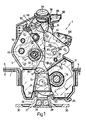
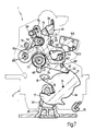
- Number 1 in Fig.s 1 to 3 indicates an electrically operated lock for the hood of a motor vehicle luggage compartment (not shown) featuring known elastic seals cooperating with the edge of the hood.
- Lock 1 is an integrated type, i.e. comprising a single assembly mounted inside the hood, on a supporting board 2 secured to the same.
- Board 2 substantially consists of a front and rear half-board 3, 4 arranged facing each other and connected at opposite sides in known manner (not shown) via permanent deformation.
- Said half-boards 3, 4 define respective pairs of superimposed lateral tabs 5, 6 having slots 7 for assembly to the hood.
- a plastic supporting element 8 of complex structure extending upwards and outwards of board 2, and having an inclined bush 9 located on the rear half-board 4 side and housing a known key-operated button 10 for manually opening lock 1.
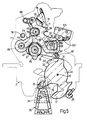
- the bottom portion of board 2 houses a latch 14 pivoting on a pin 15 supported at the ends by half-boards 3, 4 and housed in a through hole on supporting element 8.
- Latch 14 presents a pair of teeth 16, 17 defining a U-shaped recess 18 and substantially facing a cavity 19 on supporting element 8 communicating with a bottom opening 20 on board 2.
- Pin 15 of latch 14 presents a helical spring 24, the ends of which cooperate in known manner with latch 14 and board 2.
- Said spring 24 provides for forcing latch 14 into an open position wherein the back of tooth 17 cooperates with a stop 25 formed in board 2, and tooth 16 extends obliquely inside cavity 19 of supporting element 8, for intercepting a locating element 26 secured to the bodywork of the luggage compartment.
- latch 14 also presents a projection 31 defined laterally, on the side facing tooth 16, by a flat side face 32. Between tooth 16 and side 32, fork 14 presents a convex outer surface 33 substantially in the form of an arc of a circle.
- Said locating element 26 substantially consists of a shaped metal bracket 27 having a wedge-shaped central portion 28 housing a wedge-shaped plastic insert 29, and two flat end wings 30 with holes for assembly to the vehicle body. Locating element 26 presents a transverse opening 34 engaged by tooth 17 of latch 14 as described later on.
- Lock 1 also comprises a flat bolt 35 lying in the same plane as latch 14, and mounted for rotation on an eccentric intermediate portion 36 of a pin 37 having cylindrical end portions 38, 39 resting on respective bushes 40 secured via permanent deformation to respective half-boards 3, 4.
- pin 37 presents a connecting portion 44 about which is fitted a helical spring 45 secured at one end (not shown) to board 2, and the opposite end 46 of which cooperates with bolt 35 so as to maintain the tapered rounded end 52 of the same contacting latch 14.
- Pin 37 also presents a flange 47 adjacent to eccentric portion 36, and having two rounded, diametrically opposed projections 48, 49 defining cam control means as explained later on.
- Bolt 35 is maintained axially contacting flange 47 by a retaining ring 50 mounted in an annular seat on eccentric portion 36 via the interposition of a washer 51.
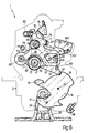
- pin 37 presents a cylindrical portion 53 having a circular, 90° radial projection 54 defined by flat radial sides 55 (Fig.4) designed to cooperate with respective mechanical locators (not shown) integral With board 2, and so define an angular displacement of 180° of pin 37.
- an axial seat 56 engaged prismatically by the output shaft 57 of an actuator 58 (shown partially in Fig.3) comprising a d.c. electric motor and a known speed reducer (not shown).
- bolt 35 Close to end 52, bolt 35 presents a rounded lateral projection 59 to which is fitted a pin 60 having its axis perpendicular to the bolt 35 plane.
- Lock 1 also comprises a release lever 64 of complex design, pivoting on a pin 65 secured to board 2 close to pin 37.
- release lever 64 presents a central portion 66 from which extend, in substantially perpendicular directions, an arm 67 having a substantially trapezoidal through slot 68, and an elongated appendix 69 pivoting at one end on pin 65. From said central portion 66, there also extend a top appendix 70, substantially opposite arm 67, and a lateral projection 71 substantially opposite appendix 69.
- Lever 64 is loaded clockwise (as viewed in Fig.5 onwards) by elastic means (not shown) by which it is maintained in the Fig.5 position wherein arm 67 cooperates with a fixed stop pin 82.
- Lock 1 also comprises a lever 74, herein referred to as a selective connecting lever for reasons which will become clear later on, and pivoting via pin 75 on the central portion 66 of release lever 64.
- Said lever 74 comprises a shaped appendix 76 extending upwards in the direction of bush 9 of supporting element 8. Substantially opposite appendix 76, lever 74 comprises a second flat, shaped appendix 77 designed to cooperate with a fixed locating pin 78 carried on board 2 close to and over pin 65.
- Lever 74 also comprises two lateral projections 79, 80 having respective end teeth 84, 85 bent 90° in opposite directions.
- tooth 84 is bent towards release lever 64, and is designed to cooperate with the side of arm 67 of lever 64. so as to define a first angular stop position between levers 64 and 74, or with the end surface of lateral projection 71 of lever 64, so as to define a second angular stop position. Tooth 85 is bent towards flange 47 and designed to cooperate with projection 48 of the same.
- Lever 74 is designed to move, in relation to lever 64, between said first and second positions, both of which, shown respectively in Fig.s 7 and 5, are rendered stable by virtue of the action of a helical spring 86 secured at the ends to lever 74 and appendix 70 of lever 64.
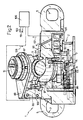
- a supporting collar 87 (Fig.s 2 and 3) is clicked on to the top portion of bush 9 housing button 10.
- Said collar 87 comprises, on one side, an integral bracket 88 supporting a microswitch 89, and, on the top front portion, a cylindrical seat 90 having its axis positioned radially in relation to collar 87 and inside which is fitted a pin 94 on which pivots a bell-crank lever 95 having an appendix 96 facing appendix 76 of lever 74.
- Bush 9 is also fitted with a sliding control collar 97 activated in known manner by button 10, which may be rendered integral with collar 97 by means of known key-operated mechanisms (not shown) housed inside bush 9.
- Said bush 9 presents known helical guide means (not shown), so that pressure on button 10 results, not only in axial displacement, but also in proportional rotation of collar 97.
- Said collar 97 presents, on one side, an appendix 99 designed to cooperate with a button 100 activating microswitch 89; and a substantially tangential arm 104 designed to cooperate with bell-crank lever 95.
- Lock 1 also comprises a second microswitch 105 secured to board 2 so that respective blade 103 is activated by projection 59 of bolt 35, as described later on.
- Reversible actuator 58 is controlled by a conventional programmable control unit 106 connected to microswitches 89, 105 and designed to receive from the same respective enabling signals 107, 108 and to supply corresponding signals 109, 110 for enabling supply of actuator 58 in both rotation directions.
- Control unit 106 features timing means for cutting off said signals when sufficient time has elapsed for enabling angular displacement of pin 37.
- Microswitches 89 and 105 may be normally-open or -closed types, by accordingly adjusting the programming of control unit 106. By way of example, however, it is assumed that microswitch 89 is normally open and 105 normally closed.
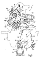
- FIG.5 shows the position of latch 14 when lock 1 is open, in which position, bolt 35 cooperates with the end surface of projection 31 of latch 14; projection 59 of bolt 35 cooperates with blade 103 of microswitch 105; and eccentric portion 36 of pin 37 is displaced, in relation to the axis of pin 37, in the opposite direction to end 52 of bolt 35.
- tooth 16 of latch 14 strikes locating element 26, and turns (clockwise in Fig.5) into the so-called secondary latched position shown by the dotted line, wherein tooth 17 engages opening 34 of locating element 26.
- Latch 14 and bolt 35 are so sized and restrained that said position is achieved with minimum compression of the hood seals and, therefore, minimum manual effort, but with the outer contour of the hood practically already flush with the rest of the vehicle body. That is to say, as regards engagement of bolt 35 and latch 14, the hood is practically in the fully latched position, the only difference being the low compression load on the hood seals.
- the eccentric portion 36 of pin 37 turns about the pin axis, taking with it bolt 35, end 52 of which is secured contacting latch 14 by spring 45.
- Bolt 35 therefore moves more or less linearly to the right in the accompanying drawings, maximum displacement being reached subsequent to 180° rotation of pin 37, at which point, the eccentricity of portion 36 is inverted in relation to the axis of pin 37.
- Tangential thrust is exerted by bolt 35 (Fig. 6) on latch 14, which rotates further by a limited but sufficient amount to bring the hood and frame closer together and so further compress the seals as required.
- electrical operation provides, not for locking, which is already provided for mechanically, but for incrementing the locking load in a manner not obtainable manually.
- actuator 58 is arrested firstly by side 55 of projection 54 on pin 37 mechanically contacting said locating means on board 2, after which, said timing means disable signal 109 and, consequently, supply to actuator 5B.
- Lock 1 is released fully automatically by operating button 10 manually from outside, or in any other manner designed to transmit an enabling signal to control unit 106 (e.g. via remote control or a button inside the passenger compartment).
- actuator 58 is activated in the opposite direction (anticlockwise in the drawings) so as to turn pin 37.
- Flange 47 and projections 48, 49 turn integral with pin 37.
- said rotation provides solely for partly reducing the load on the seals.
- lever 47 and release lever 64 turn integral with each other about pin 65, at first with no relative rotation, by virtue of the contact force line having a substantially zero arm in relation to pin 75.
- pin 37 Upon completion of the release operation by flange 47 turning 180°, pin 37 is arrested by opposite side 55 of projection 54 contacting said locating means; and supply to actuator 58 is cut off by control unit 106 via said timing means.
- lever 74 is always set to said second position after release. This is essential, in terms of reliable emergency operation, for ensuring that, once lock 1 is released, bolt 35 and lever 64 are restored correctly to the idle position, thus enabling subsequent closure.
- lock 1 may be operated electrically, thus drastically reducing the manual effort required.
- the electrical locking function is performed subsequent to mechanical locking, by directly detecting the latched position of bolt 35, thus ensuring maximum safety.
- lever 74 provides for separating electrical and emergency mechanical operation, thus reducing the manual effort required for emergency release, and enabling manual operation at any locking or release stage.
- lock 1 is of straightforward design, reliable, silent-operating and lightweight.
- the limit positions of pin 37 may be determined using encoders.
Landscapes
- Lock And Its Accessories (AREA)
- Superstructure Of Vehicle (AREA)
Applications Claiming Priority (2)
| Application Number | Priority Date | Filing Date | Title |
|---|---|---|---|
| IT5303589U IT217029Z2 (it) | 1989-04-18 | 1989-04-18 | Serratura con incremento del caricodi chiusura ed apertura elettrica particolarmente per un cofano o portellone posteriore di un autoveico lo |
| IT5303589U | 1989-04-18 |
Publications (3)
| Publication Number | Publication Date |
|---|---|
| EP0393595A2 true EP0393595A2 (de) | 1990-10-24 |
| EP0393595A3 EP0393595A3 (de) | 1991-10-16 |
| EP0393595B1 EP0393595B1 (de) | 1994-03-02 |
Family
ID=11279437
Family Applications (1)
| Application Number | Title | Priority Date | Filing Date |
|---|---|---|---|
| EP19900107275 Expired - Lifetime EP0393595B1 (de) | 1989-04-18 | 1990-04-17 | Elektrische Schliessvorrichtung, insbesondere für Haube oder Deckel von Kraftfahrzeugen |
Country Status (4)
| Country | Link |
|---|---|
| EP (1) | EP0393595B1 (de) |
| DE (1) | DE69006890T2 (de) |
| ES (1) | ES2050296T3 (de) |
| IT (1) | IT217029Z2 (de) |
Cited By (7)
| Publication number | Priority date | Publication date | Assignee | Title |
|---|---|---|---|---|
| EP0467057A3 (en) * | 1990-07-18 | 1992-02-26 | Bayerische Motoren Werke Aktiengesellschaft | Motor-assisted lock, especially for a vehicle door |
| FR2750727A1 (fr) * | 1996-07-05 | 1998-01-09 | Kiekert Ag | Serrure de vehicule automobile conformee en serrure de capot arriere |
| CN103015816A (zh) * | 2011-09-23 | 2013-04-03 | 胡夫·许尔斯贝克和福斯特有限及两合公司 | 机动车门锁 |
| EP2573301A3 (de) * | 2011-09-23 | 2014-02-19 | Huf Hülsbeck & Fürst GmbH & Co. KG | Heckschloss für ein Kraftfahrzeug |
| WO2014019851A3 (de) * | 2012-08-03 | 2014-03-27 | Huf Hülsbeck & Fürst Gmbh & Co. Kg | Kraftfahrzeugtürverschluss |
| EP3599331A1 (de) * | 2018-07-23 | 2020-01-29 | Inteva Products, LLC | Zuziehüberbrückungsmechanismus für verriegelungsanordnung |
| US11421454B2 (en) * | 2017-06-07 | 2022-08-23 | Magna Closures Inc. | Closure latch assembly with latch mechanism and outside release mechanism having reset device |
Families Citing this family (1)
| Publication number | Priority date | Publication date | Assignee | Title |
|---|---|---|---|---|
| CN110700701B (zh) * | 2018-07-09 | 2021-05-18 | 恩坦华产品有限责任公司 | 侧门锁闩总成 |
Family Cites Families (4)
| Publication number | Priority date | Publication date | Assignee | Title |
|---|---|---|---|---|
| US2950138A (en) * | 1958-06-30 | 1960-08-23 | Gen Motors Corp | Closure latch |
| US3343303A (en) * | 1965-07-27 | 1967-09-26 | Gen Motors Corp | Vehicle body deck lid operating system |
| FR2576961B1 (fr) * | 1985-02-07 | 1987-04-30 | Mecanismes Comp Ind De | Mecanisme d'assistance a la fermeture d'une porte d'un vehicule automobile |
| IT1196889B (it) * | 1986-12-30 | 1988-11-25 | Gilardini Spa | Serratura azionabile elettricamente per applicazione su autoveicoli |
-
1989
- 1989-04-18 IT IT5303589U patent/IT217029Z2/it active
-
1990
- 1990-04-17 ES ES90107275T patent/ES2050296T3/es not_active Expired - Lifetime
- 1990-04-17 DE DE1990606890 patent/DE69006890T2/de not_active Expired - Lifetime
- 1990-04-17 EP EP19900107275 patent/EP0393595B1/de not_active Expired - Lifetime
Cited By (11)
| Publication number | Priority date | Publication date | Assignee | Title |
|---|---|---|---|---|
| EP0467057A3 (en) * | 1990-07-18 | 1992-02-26 | Bayerische Motoren Werke Aktiengesellschaft | Motor-assisted lock, especially for a vehicle door |
| US5217266A (en) * | 1990-07-18 | 1993-06-08 | Bayerische Motoren Werke Ag | Door lock with a servomotor for rotating a locking pin about an eccentric axis |
| FR2750727A1 (fr) * | 1996-07-05 | 1998-01-09 | Kiekert Ag | Serrure de vehicule automobile conformee en serrure de capot arriere |
| CN103015816A (zh) * | 2011-09-23 | 2013-04-03 | 胡夫·许尔斯贝克和福斯特有限及两合公司 | 机动车门锁 |
| EP2573300A3 (de) * | 2011-09-23 | 2014-02-12 | Huf Hülsbeck & Fürst GmbH & Co. KG | Kraftfahrzeugtürverschluss |
| EP2573301A3 (de) * | 2011-09-23 | 2014-02-19 | Huf Hülsbeck & Fürst GmbH & Co. KG | Heckschloss für ein Kraftfahrzeug |
| US9273497B2 (en) | 2011-09-23 | 2016-03-01 | Huf Huelsbeck & Fuerst Gmbh & Co. Kg | Motor vehicle door latch |
| WO2014019851A3 (de) * | 2012-08-03 | 2014-03-27 | Huf Hülsbeck & Fürst Gmbh & Co. Kg | Kraftfahrzeugtürverschluss |
| US11421454B2 (en) * | 2017-06-07 | 2022-08-23 | Magna Closures Inc. | Closure latch assembly with latch mechanism and outside release mechanism having reset device |
| EP3599331A1 (de) * | 2018-07-23 | 2020-01-29 | Inteva Products, LLC | Zuziehüberbrückungsmechanismus für verriegelungsanordnung |
| US11180934B2 (en) | 2018-07-23 | 2021-11-23 | Inteva Products, Llc | Cinch override mechanism for latch assembly |
Also Published As
| Publication number | Publication date |
|---|---|
| IT8953035V0 (it) | 1989-04-18 |
| DE69006890D1 (de) | 1994-04-07 |
| ES2050296T3 (es) | 1994-05-16 |
| IT217029Z2 (it) | 1991-10-29 |
| EP0393595B1 (de) | 1994-03-02 |
| DE69006890T2 (de) | 1994-06-16 |
| EP0393595A3 (de) | 1991-10-16 |
Similar Documents
| Publication | Publication Date | Title |
|---|---|---|
| EP0397966B1 (de) | Elektrische Türschliessvorrichtung, insbesondere für Kraftfahrzeuge | |
| KR101557168B1 (ko) | 자동차의 개방을 위한 폐쇄 보조 전기 잠금 장치 | |
| US7232161B2 (en) | Latch device for vehicle tailgate | |
| US4452058A (en) | Latch, in particular for an automobile vehicle door | |
| KR100445035B1 (ko) | 도어록 구동장치 | |
| EP0834631B1 (de) | Kraftfahrzeugtürschloss | |
| US4664430A (en) | Electrically opened and closed latch for automobile vehicle doors | |
| EP0942134B1 (de) | Elektrischer Schliessmechanismus mit einer zusätzlichen türinnenseitigen mechanischen Entriegelungseinrichtung | |
| US4948184A (en) | Motor vehicle door lock | |
| GB2330620A (en) | Electric drive device | |
| EP0393595B1 (de) | Elektrische Schliessvorrichtung, insbesondere für Haube oder Deckel von Kraftfahrzeugen | |
| JPH0654064B2 (ja) | 閉鎖くさびと止め金を有する自動車ドア錠 | |
| US11598129B2 (en) | Smart latch assembly with double pawl latch mechanism having flexible connection to release mechanism | |
| US8632106B2 (en) | Drive unit comprising a blocked functional element for a central locking mechanism | |
| EP0710755B2 (de) | Elektrisch betätigtes Autotürschloss | |
| US6522095B2 (en) | Motor vehicle door lock | |
| EP0148874A1 (de) | Elektrisch betätigter fahrzeugtürverschluss | |
| JP5050275B2 (ja) | ドアラッチアクチュエータ | |
| CN110528978B (zh) | 一种一体式上吸锁 | |
| US6595561B1 (en) | Closure, especially for vehicles | |
| CN114270004B (zh) | 用于机动车的闭锁装置 | |
| US5777395A (en) | Safety actuation of vehicle door-handle operated door locks using series connected switches and electric actuator | |
| JPH0223668B2 (de) | ||
| EP1081317B1 (de) | Türverriegelungseinrichtung mit automatischer Schliessvorrichtung | |
| US20250179841A1 (en) | Motor vehicle lock, in particular motor vehicle door lock |
Legal Events
| Date | Code | Title | Description |
|---|---|---|---|
| PUAI | Public reference made under article 153(3) epc to a published international application that has entered the european phase |
Free format text: ORIGINAL CODE: 0009012 |
|
| AK | Designated contracting states |
Kind code of ref document: A2 Designated state(s): DE ES FR GB |
|
| PUAL | Search report despatched |
Free format text: ORIGINAL CODE: 0009013 |
|
| AK | Designated contracting states |
Kind code of ref document: A3 Designated state(s): DE ES FR GB |
|
| 17P | Request for examination filed |
Effective date: 19920414 |
|
| 17Q | First examination report despatched |
Effective date: 19930430 |
|
| GRAA | (expected) grant |
Free format text: ORIGINAL CODE: 0009210 |
|
| AK | Designated contracting states |
Kind code of ref document: B1 Designated state(s): DE ES FR GB |
|
| REF | Corresponds to: |
Ref document number: 69006890 Country of ref document: DE Date of ref document: 19940407 |
|
| ET | Fr: translation filed | ||
| REG | Reference to a national code |
Ref country code: ES Ref legal event code: FG2A Ref document number: 2050296 Country of ref document: ES Kind code of ref document: T3 |
|
| PLBE | No opposition filed within time limit |
Free format text: ORIGINAL CODE: 0009261 |
|
| STAA | Information on the status of an ep patent application or granted ep patent |
Free format text: STATUS: NO OPPOSITION FILED WITHIN TIME LIMIT |
|
| 26N | No opposition filed | ||
| REG | Reference to a national code |
Ref country code: GB Ref legal event code: 732E |
|
| REG | Reference to a national code |
Ref country code: FR Ref legal event code: CD Ref country code: FR Ref legal event code: CJ Ref country code: FR Ref legal event code: TP |
|
| REG | Reference to a national code |
Ref country code: ES Ref legal event code: PC2A |
|
| REG | Reference to a national code |
Ref country code: GB Ref legal event code: IF02 |
|
| REG | Reference to a national code |
Ref country code: GB Ref legal event code: 732E |
|
| REG | Reference to a national code |
Ref country code: FR Ref legal event code: CD |
|
| REG | Reference to a national code |
Ref country code: FR Ref legal event code: TP |
|
| PGFP | Annual fee paid to national office [announced via postgrant information from national office to epo] |
Ref country code: GB Payment date: 20050413 Year of fee payment: 16 |
|
| PGFP | Annual fee paid to national office [announced via postgrant information from national office to epo] |
Ref country code: ES Payment date: 20050427 Year of fee payment: 16 |
|
| PG25 | Lapsed in a contracting state [announced via postgrant information from national office to epo] |
Ref country code: GB Free format text: LAPSE BECAUSE OF NON-PAYMENT OF DUE FEES Effective date: 20060417 |
|
| PG25 | Lapsed in a contracting state [announced via postgrant information from national office to epo] |
Ref country code: ES Free format text: LAPSE BECAUSE OF NON-PAYMENT OF DUE FEES Effective date: 20060418 |
|
| GBPC | Gb: european patent ceased through non-payment of renewal fee |
Effective date: 20060417 |
|
| REG | Reference to a national code |
Ref country code: ES Ref legal event code: FD2A Effective date: 20060418 |
|
| PGFP | Annual fee paid to national office [announced via postgrant information from national office to epo] |
Ref country code: DE Payment date: 20090409 Year of fee payment: 20 Ref country code: FR Payment date: 20090417 Year of fee payment: 20 |
|
| PG25 | Lapsed in a contracting state [announced via postgrant information from national office to epo] |
Ref country code: DE Free format text: LAPSE BECAUSE OF EXPIRATION OF PROTECTION Effective date: 20100417 |