EP0393619B1 - Appareil pour traitement d'images - Google Patents
Appareil pour traitement d'images Download PDFInfo
- Publication number
- EP0393619B1 EP0393619B1 EP90107339A EP90107339A EP0393619B1 EP 0393619 B1 EP0393619 B1 EP 0393619B1 EP 90107339 A EP90107339 A EP 90107339A EP 90107339 A EP90107339 A EP 90107339A EP 0393619 B1 EP0393619 B1 EP 0393619B1
- Authority
- EP
- European Patent Office
- Prior art keywords
- image
- level
- certain value
- signals
- long
- Prior art date
- Legal status (The legal status is an assumption and is not a legal conclusion. Google has not performed a legal analysis and makes no representation as to the accuracy of the status listed.)
- Expired - Lifetime
Links
- 238000012545 processing Methods 0.000 title claims description 28
- 239000008186 active pharmaceutical agent Substances 0.000 claims description 33
- 238000013459 approach Methods 0.000 claims description 8
- 238000012935 Averaging Methods 0.000 claims description 7
- 230000009467 reduction Effects 0.000 description 8
- 238000010586 diagram Methods 0.000 description 5
- 230000008859 change Effects 0.000 description 3
- 238000010276 construction Methods 0.000 description 3
- 230000000875 corresponding effect Effects 0.000 description 3
- 238000000034 method Methods 0.000 description 3
- 230000008569 process Effects 0.000 description 3
- 238000012546 transfer Methods 0.000 description 3
- 230000003287 optical effect Effects 0.000 description 2
- 230000002596 correlated effect Effects 0.000 description 1
- 230000007423 decrease Effects 0.000 description 1
- 230000014509 gene expression Effects 0.000 description 1
- 238000003672 processing method Methods 0.000 description 1
- 238000000926 separation method Methods 0.000 description 1
Images



Classifications
-
- H—ELECTRICITY
- H04—ELECTRIC COMMUNICATION TECHNIQUE
- H04N—PICTORIAL COMMUNICATION, e.g. TELEVISION
- H04N1/00—Scanning, transmission or reproduction of documents or the like, e.g. facsimile transmission; Details thereof
- H04N1/40—Picture signal circuits
- H04N1/409—Edge or detail enhancement; Noise or error suppression
- H04N1/4092—Edge or detail enhancement
Definitions
- the present invention relates to an image processing apparatus, and more specifically to an image processing apparatus wherein image signals obtained from a continuous-tone image and unsharp signals produced from the image signals are mixed together using each of weighted parameters to be selected according to the level of density of the continuous-tone image, thereby to enable noise to be appropriately reduced over a wide range from a shadow area to a highlight when the continuous-tone image is reproduced using the mixed image signals.
- the present invention achieves its object by providing an apparatus comprising the features set out in claim 1.
- the unsharp signal generating means comprises an addition averaging circuit for adding image signals S corresponding to an even number of pixels arranged to form a continuous-tone image to be scanned in a main scanning direction and for calculating the average of the added signals to thereby generate unsharp signals.
- the unsharp signal generating means comprises an addition averaging circuit for adding the image signals S corresponding to the even number of pixels arranged to form the continuous-tone image to be scanned in a main scanning direction and image signals S corresponding to an even number of pixels arranged to form a continuous-tone image to be scanned in an auxiliary scanning direction and for calculating the average of the added signals to thereby generate unsharp signals U.
- the weighted parameter generating means comprises a look-up table of a type wherein the weighted parameter P is established such that it indicates zero as long as the level of each of the image signals S increases from zero to a certain value D H on the side of a highlight, it gradually approaches one as long as its level increases from the certain value D H to a certain value D S on the side of a shadow area and it indicates one as long as its level increases from the certain value D S to over D S , and the weighted parameter Q is established such that it indicates one as long as the level of each of the image signals S increases from zero to the certain value D H , it gradually approaches zero as long as its level increases from the certain value D H to the certain value D S and it indicates zero as long as its level increases from the certain value D S to over D S , whereby the weighted parameters P and Q are selected depending on the level of each of the image signals S.
- the weighted parameter generating means comprises a look-up table of a type wherein the weighted parameter P is established such that it indicates zero as long as the level of each of unsharp signals U increases from zero to a certain value D H on the side of a highlight, it gradually approaches one as long as its level increases from the certain value D H to a certain value D S on the side of a shadow area and it indicates one as long as its level increases from the certain value D S to over D S , and the weighted parameter Q is established such that it indicates one as long as the level of each of the image signals U increases from zero to the certain value D H , it gradually approaches zero as long as its level increases from the certain value D H to the certain value D S and it indicates zero as long as its level increases from the certain value D S to over D S , whereby the weighted parameters P and Q are selected depending on the level of each of the unsharp signals U.
- FIG. 10 designated at numeral 10 is an image reading and recording system to which an image processing apparatus according to the present embodiment is applied.
- image reading and recording system 10 continuous-tone images each of which is recorded on an original G is converted into an electric signal, followed by reproduction of the same as a halftone dot image on a photographic film F.
- the original G is fed in an auxiliary scanning direction indicated by the arrow A by an unillustrated feeding means.
- the continuous-tone image recorded on the original G is scanned in a main scanning direction indicated by the arrow B by a CCD 14 as a photoelectric converting means through a beam-condensing optical system 12.
- Each continuous-tone image, which has photoelectrically been converted by the CCD 14 is converted into each of image signals S in the form of a digital signal by an A/D converter 18 based on a main scanning clock signal ⁇ X from a clock generator 16, and thereafter supplied to the image processing unit 20.
- each image signal S is subjected to image processing such as average processing, sharpness emphasis processing, halftone separation processing, etc.
- the image recording unit 22 serves to convert the halftone dot image signal R into a light signal such as a laser beam signal for bringing the signal thus converted on a photographic signal F, thereby recording a halftone dot image.
- FIG. 2 shows the construction of the image processing unit 20 depicted in FIG. 1.
- the image processing unit 20 is provided with an unsharp signal generator unit 24, a look-up table 26 and a halftone dot image signal generator unit 28.
- the unsharp signal generator unit 24 serves to process each image signal S for average so as to generate each of unsharp signals U.
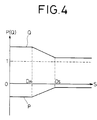
- the look-up table 26 functions as a weighted parameter generating means and generates weighted parameters P(S) and Q(S) having characteristics shown in FIG. 3 based on each image signal S.
- P(S) and Q(S) indicate that the parameters P and Q are a function of the image signal S.
- the weighted parameter P(S) indicates zero as long as the level of each image signal S increases from zero to D H on the side of a highlight, i.e., the lightest spot or area, and it gradually reaches one for a period during which its level increases from D H to D S on the side of a shadow area.
- the parameter P(S) is also set as a function representative of 1 as long as its level increases from D S to over D S .
- the weighted parameter Q(S) indicates one for a period during which the level of each of the image signals S increases from zero to D H and it gradually reaches zero for a period during which its level increases from D H to D S .
- the weighted parameter P(Q) is also set as a function indicative of zero for a period during which its level increases from D S to over D S .
- Each of the unsharp signals U generated by the unsharp signal generator unit 24 and the weighted parameter P(S) from the look-up table 26 are multiplied by a multiplier 30, followed by supply of the result to an adder 32. Then, multiplication of each one of the image signals S and the weighted parameter Q(S) from the look-up table 26 is performed by a multiplier 34, followed by supply of the result to the adder 32.
- Each of image signals T as an output from the adder 32 is supplied to the halftone dot image signal generator unit 28. At this time, the halftone dot image signal generator unit 28 generates each of halftone dot image signals R from the total image signal T and then sends the same to the image recording unit 22.
- the image reading and recording system 10 to which the image processing apparatus according to the present embodiment is applied is basically constructed as described above. A description will next be made on operation of the system.
- the CCD 14 serves to scan each of continuous-tone images recorded on the original G fed in the auxiliary scanning direction indicated by the arrow A in the main scanning direction indicated by the arrow B through the beam-condensing optical system 12, and then convert the scanned images into electric signals. Then, each of the continuous-tone images, which have been converted into the electric signals, is converted into a digital signal by the A/D converter 18 based on the main scanning clock signal ⁇ X from the clock generator 16 so as to obtain each of image signals S.
- the image signal S is transferred to the image processing unit 20, and then supplied there from to the unsharp signal generator unit 24, the look-up table 26 and the multiplier 34 successively (see FIG. 2).
- each unsharp signal U is generated based on each image signal S at the unsharp signal generator unit 24.
- it is desired to two-dimensionally average the image signals S in both main and auxiliary directions even pairs of image signals S KL adjacent to one another in the two-dimensional direction are added together and then averaged.
- the total unsharp signal U ij is produced according to the following equation:
- the CCD 14 is generally provided with two transfer registers.
- the image processing is rendered high-speed by taking out image signals one every other signal from each one of the photoelectric converter units constituting the CCD 14 and then transferring the image signals thus taken using these transfer registers.
- the unsharp signal U U i or U ij
- a preferred unsharp signal U obtained by averaging irregularity in outputs caused by the difference in property between the two transfer registers can be achieved.
- the look-up table 26 serves to select the weighted parameters P(S) and Q(S) with characteristics shown in FIG. 3 according to each image signal S, and to supply the same to the multiplier 30 and 34 respectively.
- the multiplier 30 serves to perform multiplication of the unsharp signal U and the weighted parameter P(S) for supplying the multiplied result to the adder 32.
- the multiplier 34 also serves to carry out multiplication of each image signal S and the weighted parameter Q(S) for supplying the multiplied result to the adder 32. Then, the adder 32 adds these signals together and then supplies the total image signal T as the added result determined by the following equation to the halftone dot image signal generator unit 28.
- the halftone dot image signal generator unit 28 generates a halftone dot image signal R based on the image signal T, and supplies the same to the image recording unit 22. Then, the image recording unit 22 serves to form a halftone dot image on the photographic film F based on the halftone dot image signal R.
- the image signal T becomes equal to S judging from the equation (4).
- a image signal T is therefore supplied to the halftone dot image signal generator unit 28 without processing of the same for average. Accordingly, the image which appears on the side of the highlight is recorded on the photographic film F without any reduction of resolution.
- FIG. 5 illustrates another embodiment of the image processing unit 20 shown in FIG. 2.
- Designated at numeral 40 is an image processing unit, which in turn serves to select weighted parameters P(U) and Q(U) established on a look-up table 26 based on each of unsharp signals U outputted from an unsharp signal generator unit 24, and to supply the selected parameter to multipliers 30 and 34.
- the weighted parameters P(U) and Q(U) are selected from the look-up table 26 based on the averaged unsharp signal U.
- each image signal and each unsharp signal produced by the image signal referred to above are mixed together using a weighted parameter to be selected depending on the density level of an image so as to obtain a new image signal.
- a weighted parameter to be selected depending on the density level of an image so as to obtain a new image signal.
Landscapes
- Engineering & Computer Science (AREA)
- Multimedia (AREA)
- Signal Processing (AREA)
- Facsimile Image Signal Circuits (AREA)
- Image Processing (AREA)
Claims (6)
- Appareil de traitement d'image comprenant :
des moyens de génération de signal sans forte discontinuité (24) pour traiter un signal d'image S obtenu à partir d'images en demi-teintes de manière à générer un signal sans forte discontinuité U par un calcul de moyenne entre des pixels adjacents du signal d'image S ;
des moyens de génération de paramètres pondérés (26) pour générer des paramètres pondérés P et Q ; et
des moyens de production de signal d'image (30, 32, 34) pour produire le nouveau signal d'image T selon l'équation suivante :
S est un signal d'image,
U est un signal sans forte discontinuité,
P et Q sont des paramètres pondérés,
caractérisé en ce que :
chacun desdits paramètres pondérés générés P et Q est établi selon une fonction continue arbitraire soit du niveau dudit signal d'image S soit du niveau dudit signal sans forte discontinuité U. - Appareil selon la revendication 1, dans lequel lesdits moyens de génération de signal sans forte discontinuité (24) comprennent un circuit de calcul de moyenne d'addition pour additionner des signaux d'image S correspondant à un nombre pair de pixels agencés de manière à former une image en demi-teintes devant être balayée selon une direction de balayage principal et pour calculer la moyenne des signaux additionnés pour générer ainsi des signaux sans forte discontinuité U.
- Appareil selon la revendication 1, dans lequel lesdits moyens de génération de signal sans forte discontinuité (24) comprennent un circuit de calcul de moyenne d'addition pour additionner les signaux d'image S correspondant au nombre pair de pixels agencés de manière à former une image en demi-teintes devant être balayée selon une direction de balayage principal et des signaux d'image S correspondant à un nombre pair de pixels agencés de manière à former une image en demi-teintes devant être balayée selon une direction de balayage auxiliaire et pour calculer la moyenne des signaux additionnés pour générer ainsi des signaux sans forte discontinuité U.
- Appareil selon l'une quelconque des revendications 1 à 3, dans lequel lesdits moyens de génération de paramètres pondérés (26) comprennent une table de consultation d'un type dans lequel le paramètre pondéré P est établi de manière à ce qu'il indique la valeur zéro tant que le niveau de chacun des signaux d'image S augmente de zéro jusqu'à une certaine valeur DH sur le côté de forte luminosité, il se rapproche progressivement de un tant que son niveau s'accroît d'une certaine valeur DH jusqu'à une certaine valeur DS sur le côté d'une zone sombre et il indique un tant que son niveau s'accroît d'une certaine valeur DS jusqu'au dessus de DS, et le paramètre pondéré Q est établi de manière à ce qu'il indique un tant que le niveau de chacun des signaux d'image S s'accroît de zéro jusqu'à la certaine valeur DH, il se rapproche progressivement de zéro tant que son niveau s'accroît d'une certaine valeur DH jusqu'à la certaine valeur DS et il indique zéro tant que son niveau s'accroît de la certaine valeur DS jusqu'au dessus de DS, de telle sorte que les paramètres pondérés P et Q soient sélectionnés en fonction du niveau de chacun des signaux d'image S.
- Appareil selon l'une quelconque des revendications 1 à 3, dans lequel lesdits moyens de génération de paramètres pondérés (26) comprennent une table de consultation d'un type dans lequel le paramètre pondéré P est établi de manière à ce qu'il indique zéro tant que le niveau de chacun des signaux sans forte discontinuité U s'accroît de zéro jusqu'à une certaine valeur DH sur le côté de forte luminosité, il se rapproche progressivement de un tant que son niveau augmente d'une certaine valeur DH jusqu'à une certaine valeur DS sur le côté d'une zone d'ombre et il indique un tant que son niveau s'accroît depuis la certaine valeur DS jusqu'au delà de DS, et le paramètre pondéré Q est établi de manière à ce qu'il indique un tant que le niveau de chacun des signaux d'image U s'accroît de zéro jusqu'à la certaine valeur DH, il se rapproche progressivement de zéro tant que son niveau s'accroît depuis la certaine valeur DH jusqu'à la certaine valeur DS et il indique zéro tant que son niveau s'accroît de la certaine valeur DS jusqu'au dessus de DS, de telle sorte que les paramètres pondérés P et Q soient sélectionnés selon le niveau de chacun des signaux sans forte discontinuité U.
- Appareil selon l'une quelconque des revendications 1 à 3, dans lequel lesdits moyens de génération de paramètres pondérés (26) comprennent la table de consultation pour établir les paramètres pondérés P et Q tels qu'exprimés par les équations qui suivent et pour sélectionner les paramètres pondérés P et Q en fonction des signaux d'image S,
P(S) = - K
Q(S) = 1 + K
où K est un paramètre de degré de discontinuité de chaque signal d'image S.
Applications Claiming Priority (2)
| Application Number | Priority Date | Filing Date | Title |
|---|---|---|---|
| JP1099763A JPH02278383A (ja) | 1989-04-19 | 1989-04-19 | 画像処理装置 |
| JP99763/89 | 1989-04-19 |
Publications (3)
| Publication Number | Publication Date |
|---|---|
| EP0393619A2 EP0393619A2 (fr) | 1990-10-24 |
| EP0393619A3 EP0393619A3 (fr) | 1991-01-30 |
| EP0393619B1 true EP0393619B1 (fr) | 1995-07-05 |
Family
ID=14256017
Family Applications (1)
| Application Number | Title | Priority Date | Filing Date |
|---|---|---|---|
| EP90107339A Expired - Lifetime EP0393619B1 (fr) | 1989-04-19 | 1990-04-18 | Appareil pour traitement d'images |
Country Status (4)
| Country | Link |
|---|---|
| US (1) | US5051842A (fr) |
| EP (1) | EP0393619B1 (fr) |
| JP (1) | JPH02278383A (fr) |
| DE (1) | DE69020622T2 (fr) |
Families Citing this family (23)
| Publication number | Priority date | Publication date | Assignee | Title |
|---|---|---|---|---|
| US5191439A (en) * | 1989-10-27 | 1993-03-02 | Fuji Photo Film Co., Ltd. | Image signal processing apparatus |
| US5485534A (en) * | 1990-03-28 | 1996-01-16 | Fuji Photo Film Co., Ltd. | Method and apparatus for emphasizing sharpness of image by detecting the edge portions of the image |
| JP3003799B2 (ja) * | 1990-03-28 | 2000-01-31 | 富士写真フイルム株式会社 | 画像の鮮鋭度強調方法及びその装置 |
| US5513016A (en) * | 1990-10-19 | 1996-04-30 | Fuji Photo Film Co. | Method and apparatus for processing image signal |
| JP3159465B2 (ja) * | 1991-05-17 | 2001-04-23 | 株式会社東芝 | 画像表示装置 |
| US5412489A (en) * | 1991-06-29 | 1995-05-02 | Minolta Camera Kabushiki Kaisha | Shading correction having a line memory read which generates an average reference level from a plurality of lines of a reference plate |
| JP3568279B2 (ja) * | 1995-06-30 | 2004-09-22 | 富士写真フイルム株式会社 | 画像再生方法および装置 |
| US6118906A (en) * | 1998-02-03 | 2000-09-12 | Eastman Kodak Company | Sharpening system adjusted for measured noise of photofinishing images |
| US6091861A (en) * | 1998-02-03 | 2000-07-18 | Eastman Kodak Company | Sharpening algorithm adjusted for measured exposure of photofinishing images |
| JP2000349976A (ja) * | 1999-03-26 | 2000-12-15 | Canon Inc | 画像入力装置及びその制御方法及び記憶媒体 |
| JP3730872B2 (ja) | 2000-03-31 | 2006-01-05 | 富士通株式会社 | 画像処理装置及び画像処理プログラム |
| CA2347181A1 (fr) | 2000-06-13 | 2001-12-13 | Eastman Kodak Company | Diverses presentations d'une photo sur un support d'enregistrement photographique couleur permettant la selection |
| US6781724B1 (en) * | 2000-06-13 | 2004-08-24 | Eastman Kodak Company | Image processing and manipulation system |
| JP3804447B2 (ja) * | 2000-12-20 | 2006-08-02 | セイコーエプソン株式会社 | 画像読み取り装置 |
| JP3719213B2 (ja) * | 2002-01-16 | 2005-11-24 | ノーリツ鋼機株式会社 | 画像処理装置、画像処理方法、画像処理プログラム、および画像処理プログラムを記録した記録媒体 |
| JP2003208610A (ja) * | 2002-01-16 | 2003-07-25 | Noritsu Koki Co Ltd | 画像処理装置、画像処理方法、画像処理プログラム、および画像処理プログラムを記録した記録媒体 |
| JP3826047B2 (ja) * | 2002-02-13 | 2006-09-27 | キヤノン株式会社 | 露光装置、露光方法、及びそれを用いたデバイス製造方法 |
| US7228004B2 (en) * | 2002-09-05 | 2007-06-05 | Eastman Kodak Company | Method for sharpening a digital image |
| US7269300B2 (en) * | 2003-10-24 | 2007-09-11 | Eastman Kodak Company | Sharpening a digital image in accordance with magnification values |
| TWI260913B (en) * | 2005-04-29 | 2006-08-21 | Avision Inc | Multi-stage scanning method for increasing scanning speed and enhancing image quality |
| JP4858610B2 (ja) * | 2007-02-28 | 2012-01-18 | 株式会社ニコン | 画像処理方法 |
| US8120679B2 (en) * | 2008-08-01 | 2012-02-21 | Nikon Corporation | Image processing method |
| JP2012141812A (ja) * | 2010-12-29 | 2012-07-26 | Sony Corp | 画像処理装置、画像処理方法、およびプログラム |
Family Cites Families (5)
| Publication number | Priority date | Publication date | Assignee | Title |
|---|---|---|---|---|
| DE3341371C2 (de) * | 1982-11-16 | 1989-09-21 | Dainippon Ink And Chemicals, Inc., Tokio/Tokyo | Verfahren und Einrichtung zum Erzeugen eines kombinierten Bildsignals |
| JPS60169274A (ja) * | 1984-02-10 | 1985-09-02 | Dainippon Screen Mfg Co Ltd | 画像走査記録装置に於ける輪郭強調信号処理方法 |
| JPS6195669A (ja) * | 1984-10-16 | 1986-05-14 | Dainippon Screen Mfg Co Ltd | 画像処理方法 |
| JPS63156475A (ja) * | 1986-12-19 | 1988-06-29 | Dainippon Screen Mfg Co Ltd | 多階調画像読取装置 |
| US4972256A (en) * | 1988-02-05 | 1990-11-20 | Dainippon Screen Mfg. Co., Ltd. | Method of enhancing image sharpness for image reproduction using sharp/unsharp signal processing |
-
1989
- 1989-04-19 JP JP1099763A patent/JPH02278383A/ja active Pending
-
1990
- 1990-04-17 US US07/509,840 patent/US5051842A/en not_active Expired - Lifetime
- 1990-04-18 EP EP90107339A patent/EP0393619B1/fr not_active Expired - Lifetime
- 1990-04-18 DE DE69020622T patent/DE69020622T2/de not_active Expired - Fee Related
Also Published As
| Publication number | Publication date |
|---|---|
| EP0393619A2 (fr) | 1990-10-24 |
| DE69020622D1 (de) | 1995-08-10 |
| US5051842A (en) | 1991-09-24 |
| DE69020622T2 (de) | 1995-11-30 |
| EP0393619A3 (fr) | 1991-01-30 |
| JPH02278383A (ja) | 1990-11-14 |
Similar Documents
| Publication | Publication Date | Title |
|---|---|---|
| EP0393619B1 (fr) | Appareil pour traitement d'images | |
| EP0348145B1 (fr) | Appareil de formation et de traitement d'images | |
| US6198841B1 (en) | Color image processor | |
| US5666443A (en) | Image processor with edge emphasis of image data | |
| EP0365037B1 (fr) | Procédé et appareil de traitement de signaux d'image | |
| US6192152B1 (en) | Image processing apparatus | |
| EP1505821B1 (fr) | Appareil et procédé de traitement d'images et appareil de formation d'images | |
| US5420938A (en) | Image processing apparatus | |
| US6049635A (en) | Dotted image area detecting apparatus and dotted image area detecting method | |
| EP0591274B1 (fr) | Systeme ameliore a diffusion d'erreur | |
| EP0223601B1 (fr) | Procédé de traitement d'images | |
| EP0402162B1 (fr) | Traitement d'image avec opérateurs d'amélioration du bruit pour la réduction de moiré et/ou la génération des pointes aléatoires | |
| US5087972A (en) | Method of and apparatus for processing image signals at a point of interest based on image signal curvature | |
| JPH0568146B2 (fr) | ||
| EP0424967B1 (fr) | Dispositif pour le traitement de signaux d'images | |
| EP0382580B1 (fr) | Dispositif pour le traitement d'images | |
| EP0559470B1 (fr) | Appareil utilisant l'analyse de l'histogramme de teinte | |
| JPH01115271A (ja) | 画像処理装置 | |
| JP3245600B2 (ja) | 画像処理装置 | |
| JPH0690724B2 (ja) | 画像の輪郭強調方法 | |
| JP3049262B2 (ja) | 画像補正装置 | |
| JP2634939B2 (ja) | 画像処理装置 | |
| JP3183788B2 (ja) | 網点領域判定装置 | |
| JP3751422B2 (ja) | 画像読取装置 | |
| JPH05130439A (ja) | 画像処理装置 |
Legal Events
| Date | Code | Title | Description |
|---|---|---|---|
| PUAI | Public reference made under article 153(3) epc to a published international application that has entered the european phase |
Free format text: ORIGINAL CODE: 0009012 |
|
| 17P | Request for examination filed |
Effective date: 19900418 |
|
| AK | Designated contracting states |
Kind code of ref document: A2 Designated state(s): DE FR GB |
|
| PUAL | Search report despatched |
Free format text: ORIGINAL CODE: 0009013 |
|
| AK | Designated contracting states |
Kind code of ref document: A3 Designated state(s): DE FR GB |
|
| 17Q | First examination report despatched |
Effective date: 19930317 |
|
| GRAA | (expected) grant |
Free format text: ORIGINAL CODE: 0009210 |
|
| AK | Designated contracting states |
Kind code of ref document: B1 Designated state(s): DE FR GB |
|
| REF | Corresponds to: |
Ref document number: 69020622 Country of ref document: DE Date of ref document: 19950810 |
|
| ET | Fr: translation filed | ||
| PLBE | No opposition filed within time limit |
Free format text: ORIGINAL CODE: 0009261 |
|
| STAA | Information on the status of an ep patent application or granted ep patent |
Free format text: STATUS: NO OPPOSITION FILED WITHIN TIME LIMIT |
|
| 26N | No opposition filed | ||
| REG | Reference to a national code |
Ref country code: GB Ref legal event code: IF02 |
|
| REG | Reference to a national code |
Ref country code: GB Ref legal event code: 732E |
|
| REG | Reference to a national code |
Ref country code: FR Ref legal event code: CD Ref country code: FR Ref legal event code: TP |
|
| PGFP | Annual fee paid to national office [announced via postgrant information from national office to epo] |
Ref country code: DE Payment date: 20080424 Year of fee payment: 19 Ref country code: FR Payment date: 20080312 Year of fee payment: 19 |
|
| PGFP | Annual fee paid to national office [announced via postgrant information from national office to epo] |
Ref country code: GB Payment date: 20080423 Year of fee payment: 19 |
|
| GBPC | Gb: european patent ceased through non-payment of renewal fee |
Effective date: 20090418 |
|
| REG | Reference to a national code |
Ref country code: FR Ref legal event code: ST Effective date: 20091231 |
|
| PG25 | Lapsed in a contracting state [announced via postgrant information from national office to epo] |
Ref country code: DE Free format text: LAPSE BECAUSE OF NON-PAYMENT OF DUE FEES Effective date: 20091103 |
|
| PG25 | Lapsed in a contracting state [announced via postgrant information from national office to epo] |
Ref country code: FR Free format text: LAPSE BECAUSE OF NON-PAYMENT OF DUE FEES Effective date: 20091222 Ref country code: GB Free format text: LAPSE BECAUSE OF NON-PAYMENT OF DUE FEES Effective date: 20090418 |