EP0393833A2 - Dispositif de connexion - Google Patents
Dispositif de connexion Download PDFInfo
- Publication number
- EP0393833A2 EP0393833A2 EP90302777A EP90302777A EP0393833A2 EP 0393833 A2 EP0393833 A2 EP 0393833A2 EP 90302777 A EP90302777 A EP 90302777A EP 90302777 A EP90302777 A EP 90302777A EP 0393833 A2 EP0393833 A2 EP 0393833A2
- Authority
- EP
- European Patent Office
- Prior art keywords
- intermediate member
- channels
- connector
- walls
- connectors
- Prior art date
- Legal status (The legal status is an assumption and is not a legal conclusion. Google has not performed a legal analysis and makes no representation as to the accuracy of the status listed.)
- Granted
Links
Images

Classifications
-
- A—HUMAN NECESSITIES
- A61—MEDICAL OR VETERINARY SCIENCE; HYGIENE
- A61H—PHYSICAL THERAPY APPARATUS, e.g. DEVICES FOR LOCATING OR STIMULATING REFLEX POINTS IN THE BODY; ARTIFICIAL RESPIRATION; MASSAGE; BATHING DEVICES FOR SPECIAL THERAPEUTIC OR HYGIENIC PURPOSES OR SPECIFIC PARTS OF THE BODY
- A61H9/00—Pneumatic or hydraulic massage
- A61H9/005—Pneumatic massage
- A61H9/0078—Pneumatic massage with intermittent or alternately inflated bladders or cuffs
-
- A—HUMAN NECESSITIES
- A61—MEDICAL OR VETERINARY SCIENCE; HYGIENE
- A61H—PHYSICAL THERAPY APPARATUS, e.g. DEVICES FOR LOCATING OR STIMULATING REFLEX POINTS IN THE BODY; ARTIFICIAL RESPIRATION; MASSAGE; BATHING DEVICES FOR SPECIAL THERAPEUTIC OR HYGIENIC PURPOSES OR SPECIFIC PARTS OF THE BODY
- A61H2201/00—Characteristics of apparatus not provided for in the preceding codes
- A61H2201/50—Control means thereof
- A61H2201/5058—Sensors or detectors
- A61H2201/5071—Pressure sensors
- A61H2201/5074—Pressure sensors using electric pressure transducers with proportional output
Definitions
- the present invention relates to a connection device for connecting a source of fluid to a location or locations requiring fluid e.g. with a plurality of chambers in a pair of sleeves.
- a connection device for connecting a source of fluid to a location or locations requiring fluid e.g. with a plurality of chambers in a pair of sleeves.
- An example is the distribution of fluid under pressure to the chambers of a multichamber sleeve adapted to be placed around a limb so that pressure can be applied to the limb in a desired manner.
- the velocity of the flow of blood in a patient's limbs markedly decreases during confinement in bed of the patient.
- This decrease in the velocity of blood in the extremities causes a pooling or stasis of blod which is particularly pronounced during surgery, immediately after surgery, and when the patient has been confined to bed for extended periods of time.
- This stasis of blood is a significant cause of the formation of thrombi in the patient's extremities which may have a severe deleterious effect on the patient.
- a principal feature of the present invention is the provision of an improved connection device of simplified construction for connecting a source of fluid to the chambers in a plurality of sleeves.
- a connection device in accordance with the present invention preferably comprises an intermediate member having a pair of opposed first and second sides, and a plurality of spaced annular walls defining a plurality of separate annular channels extending substantially peripherally around the intermediate member, and first and second walls covering the opposed first and second sides of the intermediate member and closing the channels of the intermediate member, with each of the walls having opening means extending therethrough and separately communicating with each of the channels of the intermediate member.
- the device preferably has a plurality of first conduits separately communicating with each of the channels of the intermediate member to permit passage of fluid to the channels.
- the device preferably has a first connector positioned adjacent the first wall and having a plurality of annular walls defining separate annular channels extending substantially peripherally around the first connector, with each of the channels of the first connector separately communicating with the opening means of the first wall such that the channels of the first connector separately communicate with the channels of the intermediate member, with the first connector preferably being rotatable with respect to the intermediate member.
- the device preferably has a plurality of second conduits separately communicating with each of the channels of the first connector to permit passage of fluid from the channels.
- the device preferably has a second connector positioned adjacent the second wall and having a plurality of annular walls defining separate annular channels extending substantially peripherally around the second connector, with each of the channels of the second connector separately communicating with the opening means of the second wall such that the channels of the second connector separately communicate with the channels of the intermediate member, with the second connector preferably being rotatable with respect to the intermediate member.
- the device preferably has a plurality of third conduits separately communicating with each of the channels of the second connector to permit passage of fluid from the channels.
- the device has means for releasably retaining the first connector at a plurality of positions relative to the intermediate member, and preferably means for releasably retaining the second connector at a plurality of positions relative to the intermediate member.
- An advantage of the present invention is that the connector may be readily assembled and disassembled in order to connect or disconnect a sleeve which is attached to the first or second connector.
- first and second connectors may be rotated to a desired position relative to the intermediate member and retained in place.
- first and second walls comprise elastic members in order to provide seals between the intermediate member and the first and second connectors.
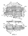
- connection device 210 having an intermediate member 212, a first connector 214, and a second connector 216.
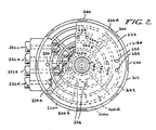
- the intermediate member 212 has a pair of opposed first and second sides 221 and 223, and a plurality of spaced annular walls 218a, 218b, 218c, 218d, and 218e defining a plurality of separate annular channels 220a, 220b, 220c, and 220d extending substantially peripherally around the intermediate member 212.
- the intermediate member 212 has first and second generally circular elastic walls 222 and 224 covering the opposed first and second sides 221 and 223 of the intermediate member 212 and enclosing the channels 220a, 220b, 220c, and 220d.
- the walls 222 and 224 have a plurality of openings 226 and 227 respectively extending therethrough separately communicating with each of the channels 220a, 220b, 220c, and 220d of the intermediate member 212.
- the intermediate member 212 has a pair of opposed bosses 228 which are received in apertures 230 of the first and second walls 222 and 224 in order to retain the first and second walls 222 and 224 in place on the intermediate member 212. In this configuration at least one of the openings 226 in both the walls 222 and 224 communicate with each of the channels 220a, 220b, 220c, and 220d in the intermediate member 212.
- the intermediate member 212 has a plurality of conduits 232a, 232b, 232c and 232d including associated passageways in the intermediate member 212 which communicate with a source of fluid which passes through the conduits 232a, b, c, and d and separate ports 234a, 234b, 234c, and 234d into the channels 220a, 220b, 220c, and 220d.
- the first connector 214 is adjacent the first wall 222
- the second connector 216 is adjacent the second wall 224. Since the first and second connectors 214 and 216 are substantially identical in structure, like reference numerals will be used to designate like parts in the connectors 214 and 216.
- the first and second connectors 214 and 216 have a plurality of separate annular walls 238a, 238b, 238c, 238d and 238e defining separate annular channels 236a, 236b, 236c, and 236d extending substantially peripherally around the connector 214 and 216.
- Each of the channels 236a, b, c, and d of the first connector 214 separately communicate with the openings 226 in the first elastic wall 222 associated with the channels 220a, 220b, 220c, and 220d of the intermediate member 212.
- each of the channels 236a, b, c and d of the second connector 216 separately communicate with the openings 227 of the second elastic wall 224 such that the channels 236a, b, c, and d of the second connector 216 communicate with the channels 22a, b, c, and d of the intermediate member 212.
- the first and second connectors 214 and 216 each have a set of conduits (first conduits 240a, b, c, and d and second conduits 241a, b, c and d) which communicate respectively through respective ports (242a, b, c, and d and 243a, b, c and d) with the separate respective channels 236a, b, c, and d and 237a, b, c and d.
- the fluid under pressure passes through the conduits 232a, b, c, and d into the channels 220a, b, c, and d of the intermediate member 212, through the openings 226 of the walls 222 and 224 into the channels 236a, b, c, and d of the first and second connectors 214 and 216 and through the conduits 240a, b, c, and d into separate chambers of a pair of sleeves, with each sleeve being associated with one of the connectors 214 and 216.
- the first and second connectors 214 and 216 have a bore 244 and 245, respectively, extending therethrough, the first and second walls 222 and 224 have bores 246 and 248, extending therethrough, and the wall 218a of the intermediate member 212 has a bore 250 extending therethrough.
- the connection device 210 has an elongated bolt 252 having a knob 254 at one end, and a threaded portion 256 adjacent the other end.
- the bore 245 of the second connector 216 is threaded 257 to receive the threaded portion 256 of the bolt 252.
- the bolt 252 may be utilized to releasably assemble the first and second connectors 214 and 216 to the intermediate member 212 while permitting rotation of the first and second connectors 214 and 216 relative to the intermediate member 212.
- the channels 220a, b, c, and d of the intermediate member communicate through the openings 226 of the first and second walls 222 and 224 with the respective channels 236a, b, c, and d of the first and second connectors 214 and 216.
- the first and second connectors 214 and 216 have an outer annular wall 270 having a plurality of spaced inwardly directed teeth 258 which are releasably received in associated notches 260 of the intermediate member 212 in order to releasably retain the first and second connectors 214 and 216 at a plurality of desired rotational positions relative to the intermediate member 212.
- the first and second connectors 214 and 216 may be moved to a number of desired rotatable positions, such as eight, and may be releasably secured in place by tightening the bolt 252.
- first and second elastic walls 222 and 224 provide seals between the intermediate member 212 and first and second connectors 214 and 216 to prevent leakage in the connection device 210.
- the first and second connectors 214 and 216 have an outer generally circular recess 262 to receive associated generally circular plates 264, with the plates 264 being retained in place in a suitable manner, such as by adhesive.
- the plate 264 of the first connector 214 has an aperture 266 to permit passage of the bolt 252 therethrough.
- the bolt 252 may be removed from the connection device 210 in order to readily disassemble the first and second connectors 214 and 216 and associated sleeves from the intermediate member 212, and permit easy assemblage of the first and second connectors 214 and 216 and the associated sleeves to the intermediate member 212 by securement of the bolt 252 in the connector device 210.
Landscapes
- Health & Medical Sciences (AREA)
- Epidemiology (AREA)
- Pain & Pain Management (AREA)
- Physical Education & Sports Medicine (AREA)
- Rehabilitation Therapy (AREA)
- Life Sciences & Earth Sciences (AREA)
- Animal Behavior & Ethology (AREA)
- General Health & Medical Sciences (AREA)
- Public Health (AREA)
- Veterinary Medicine (AREA)
- Quick-Acting Or Multi-Walled Pipe Joints (AREA)
- Manufacturing Of Electric Cables (AREA)
- Paper (AREA)
- Earth Drilling (AREA)
- Coupling Device And Connection With Printed Circuit (AREA)
- Monitoring And Testing Of Exchanges (AREA)
- Invalid Beds And Related Equipment (AREA)
- Percussion Or Vibration Massage (AREA)
- Joints Allowing Movement (AREA)
- Infusion, Injection, And Reservoir Apparatuses (AREA)
Applications Claiming Priority (2)
| Application Number | Priority Date | Filing Date | Title |
|---|---|---|---|
| US07/337,606 US4966396A (en) | 1989-04-13 | 1989-04-13 | Connection device |
| US337606 | 1989-04-13 |
Publications (3)
| Publication Number | Publication Date |
|---|---|
| EP0393833A2 true EP0393833A2 (fr) | 1990-10-24 |
| EP0393833A3 EP0393833A3 (fr) | 1991-05-15 |
| EP0393833B1 EP0393833B1 (fr) | 1994-08-03 |
Family
ID=23321229
Family Applications (1)
| Application Number | Title | Priority Date | Filing Date |
|---|---|---|---|
| EP90302777A Expired - Lifetime EP0393833B1 (fr) | 1989-04-13 | 1990-03-15 | Dispositif de connexion |
Country Status (9)
| Country | Link |
|---|---|
| US (1) | US4966396A (fr) |
| EP (1) | EP0393833B1 (fr) |
| JP (1) | JP2758963B2 (fr) |
| AT (1) | ATE109344T1 (fr) |
| AU (1) | AU623497B2 (fr) |
| CA (1) | CA2009833C (fr) |
| DE (1) | DE69011175T2 (fr) |
| DK (1) | DK0393833T3 (fr) |
| ES (1) | ES2057375T3 (fr) |
Families Citing this family (9)
| Publication number | Priority date | Publication date | Assignee | Title |
|---|---|---|---|---|
| US5478119A (en) * | 1993-09-16 | 1995-12-26 | The Kendall Company | Polarized manifold connection device |
| US6610021B1 (en) | 1994-03-28 | 2003-08-26 | Tyco Healthcare Group Lp | Integral compression sleeves and manifold tubing set |
| US7771376B2 (en) | 2000-06-02 | 2010-08-10 | Midtown Technology Ltd. | Inflatable massage garment |
| WO2004091463A2 (fr) | 2003-04-11 | 2004-10-28 | Hill-Rom Services, Inc. | Systeme de contention elastique |
| US8388557B2 (en) | 2007-06-20 | 2013-03-05 | Remo Moomiaie-Qajar | Portable compression device |
| US9737454B2 (en) | 2012-03-02 | 2017-08-22 | Hill-Rom Services, Inc. | Sequential compression therapy compliance monitoring systems and methods |
| EP3207911B1 (fr) | 2016-02-18 | 2019-04-03 | Hill-Rom Services, Inc. | Dispositif de support pour patient doté d'un dispositif de compression de membre intégré |
| US10166164B2 (en) | 2016-04-27 | 2019-01-01 | Radial Medical, Inc. | Adaptive compression therapy systems and methods |
| BR112022023393A2 (pt) * | 2020-05-22 | 2022-12-27 | Kpr Us Llc | Sistema, método e dispositivo que utiliza conector reversível |
Family Cites Families (12)
| Publication number | Priority date | Publication date | Assignee | Title |
|---|---|---|---|---|
| US2820650A (en) * | 1952-09-04 | 1958-01-21 | Westinghouse Bremsen Gmbh | Multiple conduit rotary union |
| US2781134A (en) * | 1953-06-09 | 1957-02-12 | Lee D Weir | Apparatus for controlling truck operation from crane cab |
| US3415327A (en) * | 1966-05-06 | 1968-12-10 | Deere & Co | Hydraulic coupling |
| US3862629A (en) * | 1973-05-02 | 1975-01-28 | Nicholas R Rotta | Fluid pressure controlled means for producing peristaltic operation of series-connected inflatable chambers in therapeutic devices, pumps and the like |
| US4030488A (en) * | 1975-10-28 | 1977-06-21 | The Kendall Company | Intermittent compression device |
| US4013069A (en) * | 1975-10-28 | 1977-03-22 | The Kendall Company | Sequential intermittent compression device |
| IL53123A0 (en) * | 1977-10-13 | 1977-12-30 | Hydrola Ltd | Human body treating apparatus |
| FR2413603A1 (fr) * | 1977-12-30 | 1979-07-27 | Emh | Dispositif formant joint tournant a passage multiple de tuyauterie notamment pour colonne de chargement ou de transfert en site marin |
| US4320746A (en) * | 1979-12-07 | 1982-03-23 | The Kendall Company | Compression device with improved pressure control |
| US4280485A (en) * | 1980-04-11 | 1981-07-28 | The Kendall Company | Compression device with simulator |
| US4402312A (en) * | 1981-08-21 | 1983-09-06 | The Kendall Company | Compression device |
| JP6327017B2 (ja) | 2014-06-30 | 2018-05-23 | Jfeスチール株式会社 | 厚肉かつ高強度の厚鋼板およびその製造方法 |
-
1989
- 1989-04-13 US US07/337,606 patent/US4966396A/en not_active Expired - Lifetime
-
1990
- 1990-02-12 CA CA002009833A patent/CA2009833C/fr not_active Expired - Lifetime
- 1990-02-22 AU AU50055/90A patent/AU623497B2/en not_active Expired
- 1990-03-15 AT AT90302777T patent/ATE109344T1/de not_active IP Right Cessation
- 1990-03-15 DK DK90302777.9T patent/DK0393833T3/da active
- 1990-03-15 ES ES90302777T patent/ES2057375T3/es not_active Expired - Lifetime
- 1990-03-15 DE DE69011175T patent/DE69011175T2/de not_active Expired - Lifetime
- 1990-03-15 EP EP90302777A patent/EP0393833B1/fr not_active Expired - Lifetime
- 1990-03-16 JP JP2066743A patent/JP2758963B2/ja not_active Expired - Lifetime
Also Published As
| Publication number | Publication date |
|---|---|
| DE69011175D1 (de) | 1994-09-08 |
| DK0393833T3 (da) | 1994-11-28 |
| ES2057375T3 (es) | 1994-10-16 |
| JPH0314994A (ja) | 1991-01-23 |
| DE69011175T2 (de) | 1995-03-16 |
| EP0393833A3 (fr) | 1991-05-15 |
| CA2009833C (fr) | 1999-06-29 |
| JP2758963B2 (ja) | 1998-05-28 |
| US4966396A (en) | 1990-10-30 |
| AU5005590A (en) | 1990-10-18 |
| AU623497B2 (en) | 1992-05-14 |
| EP0393833B1 (fr) | 1994-08-03 |
| ATE109344T1 (de) | 1994-08-15 |
| CA2009833A1 (fr) | 1990-10-13 |
Similar Documents
| Publication | Publication Date | Title |
|---|---|---|
| EP1104521B1 (fr) | Raccord fluidique | |
| DE19846922C2 (de) | Behandlungsvorrichtung | |
| EP0393833B1 (fr) | Dispositif de connexion | |
| US4280485A (en) | Compression device with simulator | |
| CA2552354C (fr) | Appareil de raccordement de conduit fluidique | |
| TWI471115B (zh) | 用於肢體之壓縮裝置 | |
| US4253449A (en) | Compression device with connection system | |
| US7490620B2 (en) | Fluid conduit connector apparatus | |
| US4827912A (en) | Multi-chamber porting device | |
| US4753236A (en) | Temporary anastomotic device | |
| CN1918422B (zh) | 流体管道连接装置 | |
| USD406899S (en) | Portable medical appliance for stimulating healing of wounds | |
| CA2272348A1 (fr) | Cassette integree de regulation de fluides comportant un filtre integre | |
| DK0876168T3 (da) | Implanterbar hjertehjælpepumpe af modtryksballontypen | |
| WO2000032296A3 (fr) | Filtre destine a etre utilise pour des actes medicaux | |
| RU2000112533A (ru) | Присоединительное устройство для медицинского применения | |
| AU4088996A (en) | Oscillometric blood pressure monitor with enhanced cuff pressure control | |
| AU3217295A (en) | Miniaturized blood pressure monitor kit | |
| EP0388200A2 (fr) | Manchon compressible sur toute sa longueur | |
| US6610021B1 (en) | Integral compression sleeves and manifold tubing set | |
| CA2209374A1 (fr) | Brassard pour genou avec coussin gonflable entourant la rotule | |
| US20240216211A1 (en) | Pressure differential therapeutic actuator | |
| CA2310594A1 (fr) | Appareil pour traiter les troubles circulatoires peripheriques et systeme de fermeture pour son cylindre de traitement | |
| FR2725760B1 (fr) | Electrovalve de regulation de pression hydraulique et application aux circuits de freinage | |
| RU2055562C1 (ru) | Матрац |
Legal Events
| Date | Code | Title | Description |
|---|---|---|---|
| PUAI | Public reference made under article 153(3) epc to a published international application that has entered the european phase |
Free format text: ORIGINAL CODE: 0009012 |
|
| AK | Designated contracting states |
Kind code of ref document: A2 Designated state(s): AT BE CH DE DK ES FR GB GR IT LI LU NL SE |
|
| PUAL | Search report despatched |
Free format text: ORIGINAL CODE: 0009013 |
|
| AK | Designated contracting states |
Kind code of ref document: A3 Designated state(s): AT BE CH DE DK ES FR GB GR IT LI LU NL SE |
|
| 17P | Request for examination filed |
Effective date: 19911104 |
|
| RAP1 | Party data changed (applicant data changed or rights of an application transferred) |
Owner name: THE KENDALL COMPANY |
|
| 17Q | First examination report despatched |
Effective date: 19930407 |
|
| GRAA | (expected) grant |
Free format text: ORIGINAL CODE: 0009210 |
|
| ITF | It: translation for a ep patent filed | ||
| AK | Designated contracting states |
Kind code of ref document: B1 Designated state(s): AT BE CH DE DK ES FR GB GR IT LI LU NL SE |
|
| REF | Corresponds to: |
Ref document number: 109344 Country of ref document: AT Date of ref document: 19940815 Kind code of ref document: T |
|
| REF | Corresponds to: |
Ref document number: 69011175 Country of ref document: DE Date of ref document: 19940908 |
|
| ET | Fr: translation filed | ||
| REG | Reference to a national code |
Ref country code: ES Ref legal event code: FG2A Ref document number: 2057375 Country of ref document: ES Kind code of ref document: T3 |
|
| REG | Reference to a national code |
Ref country code: GR Ref legal event code: FG4A Free format text: 3012930 |
|
| REG | Reference to a national code |
Ref country code: DK Ref legal event code: T3 |
|
| EAL | Se: european patent in force in sweden |
Ref document number: 90302777.9 |
|
| PLBE | No opposition filed within time limit |
Free format text: ORIGINAL CODE: 0009261 |
|
| STAA | Information on the status of an ep patent application or granted ep patent |
Free format text: STATUS: NO OPPOSITION FILED WITHIN TIME LIMIT |
|
| 26N | No opposition filed | ||
| REG | Reference to a national code |
Ref country code: GB Ref legal event code: IF02 |
|
| REG | Reference to a national code |
Ref country code: CH Ref legal event code: PFA Owner name: THE KENDALL COMPANY Free format text: THE KENDALL COMPANY#15 HAMPSHIRE STREET#MANSFIELD/MA (US) -TRANSFER TO- THE KENDALL COMPANY#15 HAMPSHIRE STREET#MANSFIELD/MA (US) |
|
| PGFP | Annual fee paid to national office [announced via postgrant information from national office to epo] |
Ref country code: ES Payment date: 20090326 Year of fee payment: 20 Ref country code: DK Payment date: 20090325 Year of fee payment: 20 Ref country code: AT Payment date: 20090219 Year of fee payment: 20 |
|
| PGFP | Annual fee paid to national office [announced via postgrant information from national office to epo] |
Ref country code: NL Payment date: 20090324 Year of fee payment: 20 |
|
| PGFP | Annual fee paid to national office [announced via postgrant information from national office to epo] |
Ref country code: CH Payment date: 20090325 Year of fee payment: 20 Ref country code: GR Payment date: 20090330 Year of fee payment: 20 |
|
| PGFP | Annual fee paid to national office [announced via postgrant information from national office to epo] |
Ref country code: IT Payment date: 20090331 Year of fee payment: 20 Ref country code: SE Payment date: 20090327 Year of fee payment: 20 Ref country code: DE Payment date: 20090327 Year of fee payment: 20 Ref country code: LU Payment date: 20090401 Year of fee payment: 20 |
|
| PGFP | Annual fee paid to national office [announced via postgrant information from national office to epo] |
Ref country code: BE Payment date: 20090430 Year of fee payment: 20 |
|
| PGFP | Annual fee paid to national office [announced via postgrant information from national office to epo] |
Ref country code: FR Payment date: 20090317 Year of fee payment: 20 |
|
| PGFP | Annual fee paid to national office [announced via postgrant information from national office to epo] |
Ref country code: GB Payment date: 20090403 Year of fee payment: 20 |
|
| REG | Reference to a national code |
Ref country code: NL Ref legal event code: V4 Effective date: 20100315 |
|
| BE20 | Be: patent expired |
Owner name: THE *KENDALL CY Effective date: 20100315 |
|
| REG | Reference to a national code |
Ref country code: CH Ref legal event code: PL |
|
| REG | Reference to a national code |
Ref country code: DK Ref legal event code: EUP |
|
| REG | Reference to a national code |
Ref country code: GB Ref legal event code: PE20 Expiry date: 20100314 |
|
| EUG | Se: european patent has lapsed | ||
| REG | Reference to a national code |
Ref country code: ES Ref legal event code: FD2A Effective date: 20100316 |
|
| PG25 | Lapsed in a contracting state [announced via postgrant information from national office to epo] |
Ref country code: GB Free format text: LAPSE BECAUSE OF EXPIRATION OF PROTECTION Effective date: 20100314 |
|
| PG25 | Lapsed in a contracting state [announced via postgrant information from national office to epo] |
Ref country code: ES Free format text: LAPSE BECAUSE OF EXPIRATION OF PROTECTION Effective date: 20100316 Ref country code: NL Free format text: LAPSE BECAUSE OF EXPIRATION OF PROTECTION Effective date: 20100315 |
|
| PG25 | Lapsed in a contracting state [announced via postgrant information from national office to epo] |
Ref country code: DE Free format text: LAPSE BECAUSE OF EXPIRATION OF PROTECTION Effective date: 20100315 |