EP0393931A2 - Système et procédé de traitement de cendres - Google Patents
Système et procédé de traitement de cendres Download PDFInfo
- Publication number
- EP0393931A2 EP0393931A2 EP90303965A EP90303965A EP0393931A2 EP 0393931 A2 EP0393931 A2 EP 0393931A2 EP 90303965 A EP90303965 A EP 90303965A EP 90303965 A EP90303965 A EP 90303965A EP 0393931 A2 EP0393931 A2 EP 0393931A2
- Authority
- EP
- European Patent Office
- Prior art keywords
- ash
- fluidized bed
- boiler
- vessel
- hot
- Prior art date
- Legal status (The legal status is an assumption and is not a legal conclusion. Google has not performed a legal analysis and makes no representation as to the accuracy of the status listed.)
- Ceased
Links
Images

Classifications
-
- F—MECHANICAL ENGINEERING; LIGHTING; HEATING; WEAPONS; BLASTING
- F23—COMBUSTION APPARATUS; COMBUSTION PROCESSES
- F23C—METHODS OR APPARATUS FOR COMBUSTION USING FLUID FUEL OR SOLID FUEL SUSPENDED IN A CARRIER GAS OR AIR
- F23C10/00—Fluidised bed combustion apparatus
- F23C10/18—Details; Accessories
- F23C10/24—Devices for removal of material from the bed
- F23C10/26—Devices for removal of material from the bed combined with devices for partial reintroduction of material into the bed, e.g. after separation of agglomerated parts
-
- F—MECHANICAL ENGINEERING; LIGHTING; HEATING; WEAPONS; BLASTING
- F23—COMBUSTION APPARATUS; COMBUSTION PROCESSES
- F23J—REMOVAL OR TREATMENT OF COMBUSTION PRODUCTS OR COMBUSTION RESIDUES; FLUES
- F23J2900/00—Special arrangements for conducting or purifying combustion fumes; Treatment of fumes or ashes
- F23J2900/01002—Cooling of ashes from the combustion chamber by indirect heat exchangers
Definitions
- the invention is directed to an ash treatment system and process for use in the fluidized bed combustion of waste fuels having a high ash content.
- Fluidized bed reactors are well-known means for generating heat and, in various forms, carry out processes such as drying, roasting, calcining, incineration and heat treatment of solids with gases in the chemical, metallurgical and other material processing fields.
- steam is generated for use in driving electric power generation equipment, for process heat, for space heating, or for other purposes.
- Fluidized bed reactors typically comprise a vessel in which a bed of particulate solids is present in the reaction chamber. Sufficient air or other gas is introduced into the vessel below the bed of particulate solids in a volume sufficient to achieve a gas velocity that expands or fluidizes the solids bed, suspending the particulate solids of the bed in the flowing air stream and imparting to the individual particles a continuous random motion with the fluidized bed as a whole resembling a boiling liquid.
- Conducting a combustion reaction in a fluidized bed has important advantages which include attainment of a substantially uniform bed temperature, combustion at relatively low temperatures and a high heat transfer rate.
- Combustion of solid fuels such as coal in a fluid bed reactor involves the gasification of the organic component of the fuel leaving a residue of solid ash particles.
- solid fuels such as coal
- the need to continuously remove from the combusting fluidized bed the relatively large quantities of red hot ash becomes a serious problem.
- Ash particles of somewhat larger particle sizes will become part of the fluidized bed where they improve the operation of the fluidized bed by retaining heat and contacting and igniting fresh fuel particles.
- a waste coal or anthracite may consist of two-thirds ash much of which is in the form of stone or rock and therefore tends to stay substantially in the same size range as the feed material to the fluidized bed boiler.
- a conventional cooler may be attached to the ash duct from the combustor with the ash cooled in a stream of cold air which also strips out the fines for return to the combustion compartment with the air.
- Such a unit is known as a classifier.
- the ash may be directed into a second fluidized bed and simply cooled with air or additional water-cooled tubes in the bed to remove the heat.
- Such a unit is a fluidized bed cooler.
- a third possibility is to simply have a water-cooled screw transporting the ash and removing the heat.
- fluidized bed boilers operating on waste fuels have to build up to a high carbon level in the combusting fluidized bed in order to achieve the proper combustion temperature which is typically about 1600°F. It will be understood that withdrawing the ash from the fluidized bed reactor not only removes heat from the reactor, but also removes unburned carbon which in the classifier or fluidized bed cooler largely goes to waste. A small amount of the carbon may be burned because of the air present, but the rapidly quenching nature of the cooler or classified means that the reaction rate is not maintained and significant unburned carbon is ejected from the system in the ash. This, of course, negatively impacts on overall boiler and system efficiency.
- U.S. Pat. No. 4,700,636, issued October 20, 1987 discloses an ash classifier device for returning ash fines to a fluidized bed reactor while collecting coarse ash particles for disposal. Only minor cooling of the ash particles is effected.
- U.S. Pat. No. 4,330,502 issued May 18, 1982, discloses a modified fluidized bed reactor having an ash classification system for separating and returning fines to the reactor while discharging coarse particles from the reactor.
- U.S. Pat. No. 3,397,657 discloses a fluidized bed reactor wherein non-inflammable materials are separated and discharged from the system while the fluidized medium (fines) are returned to the reactor.
- the present invention in one aspect resides in an ash treatment system for a fluidized bed reactor or boiler comprising,
- the present invention also resides in an ash treatment system for a fluidized bed boiler comprising,
- the invention resides in a process for treating hot carbon-containing ash flowing from a fluidized bed reactor or boiler comprising the steps of:
- the ash treatment system of the invention comprises one or more vessels or cells in which hot ash from a fluidized bed boiler or reactor is received and first classified to separate the fine and coarse ash fractions.
- the fine fraction is returned to the boiler and the coarse fraction is further treated by exposure to large volumes of air to secure combustion of the unburned carbon in the ash.
- the coarse ash fraction is thereafter cooled in a fluidized bed environment with the fluidizing air heated by contact with the ash and the heated air is retained in the process so that the sensible heat thereof may be utilized.
- an ash treatment vessel is located externally of the fluidized bed reactor or boiler with which it cooperates.
- the ash treatment vessel is connected to the reactor by at least two conduits; the first for receiving a hot ash solids feed with a carbon component from the reactor and, the second, for returning ash fines, some carbon particles, and hot gas to the reactor.
- Air is introduced into the ash vessel at a lower portion thereof through tuyeres spaced from the bottom of the ash vessel.
- the volume and velocity of air introduced by the tuyeres is sufficinet to establish a fluidized bed in the lower portion of said vessel, to burn significant amounts of carbon in the feed and entrain fines from the solids in the vessel volume about the level of air introduction, while permitting coarse ash to fall through an upward flow of air to the bottom of the vessel where it accumulates below the level of air introduction in the fluidized bed. Entrained fines, which include hot ash fines and some small amount of unburned carbon particles, pass upward with hot gas into the conduit which returns the solids and gas to the fluidized bed reactor or boiler.
- the air introduced into the ash vessel as fluidizing air is heated by contact with the fluidized hot ash and, further, by the combustion of carbon particles which occurs in the vessel.
- the coarse ash falls into the fluidized bed at the bottom of the ash vessel where it is cooled, some ash dropping out of the fluidized bed into an accumulation volume provided below the level of air introduction. As necessary, the ash in the accumulation volume is withdrawn from the vessel for disposal through a valved conduit which opens into the vessel bottom.
- the ash treatment system comprises a modified ash treatment vessel with one or more cooperating ash cooling cells.
- the modified ash treatment vessel carries out the classification of ash received from the boiler and the combustion of unburned carbon present in the ash, but effects little or no cooling of the ash.
- the cooling function is conducted by one or more fluidized bed cooling cells associated with the ash treatment vessel. One such cooling cell adjoins the ash treatment vessel and is in communication with the fluidized bed of the ash treatment vessel by means of a submerged weir.
- a series or train of fluidized bed cooling cells may be connected to the first cooling cell, each having a submerged weir providing communication with its neighbor.
- the heated air produced by each cooling cell may be returned to the boiler by a connecting conduit.
- Each such cooling cell can reduce the ash temperature by several hundred degrees (°F) so that the ash withdrawn from the system is at a temperature which can be readily handled.
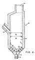
- FIG. 1 there is illustrated a fluidized bed reactor or boiler 10 connected to the ash treatment system 20 in accordance with the present invention.
- the fluidized bed reactor 10 is only partially shown and comprises a sidewall 12 which may be of water-wall construction in the case of a boiler and a bottom wall 13.
- a sidewall 12 which may be of water-wall construction in the case of a boiler and a bottom wall 13.
- an air distribution plate 15 which divides the interior space of the reactor into a windbox 14 below the air distribution plate 15 and a reaction chamber or combustion volume 17 above the air distribution plate 15.
- Means such as a blower is provided for introducing a large volume of air into the windbox 14.
- Fluidized bed material 18, 19 is located above the air distribution plate 15 within the combustion chamber 17.
- the ash treatment system 20 comprises an ash vessel 22 located at a generally lower level than the fluidized bed reactor 10 and an arrangement of conduits connecting the ash vessel to the fluidized bed reactor.
- the ash vessel has a top wall 26, a side wall 24, while the bottom of the reactor is formed by a slanted or inclined wall portion 32 which is intermediate sidewall 24 and a centrally located outlet port 33 to which ash disposal conduit 31 is fixed.
- a plurality of tuyeres 35 pass through inclined wall portion 32 and are inclined inwardly of the side wall 24 to direct streams of air into the interior of vessel 22.
- the ash disposal conduit 34 has a controlling valve 36 positioned therein.
- a downwardly inclined ash conduit 42 connects ash exit port 11 in the lower portion of the fluidized vessels bed reactor 10 just above the air distribution plate 15 with the ash vessel through a hot ash inlet port 11.
- a shut-off valve (not shown) may be provided in conduit 12.
- a return conduit 16 connects the ash vessel with the fluidized bed reactor through a gas/solids outlet port 19 in the top wall or roof 26 of the ash vessel and a return port 48 in the wall 12 of the fluidized bed reactor.
- the fluidized bed reactor or boiler 10 has within the combustion chamber 17 a body of particulate matter 18, 19 which is supported above the air distribution plate 15. Air supplied by a blower to the windbox 14 moves through the perforations of the air distribution plate 15 into the bed material 18, 19 and expands that bed to a substantial height within the combustion chamber 17.
- the expanded bed material may not have a distinct upper surface and there may be a dilute concentration of very fine particles in the upper part of the combustion chamber 17.
- the fine particles tend to leave the fluidized bed boiler through the exhaust stack (not shown) of the boiler with the exhaust gases, but centrifugal means, such as a cyclone, may be provided in the exhaust system to separate and capture fines for return to the boiler.
- the air introduced through the air distribution plate 15 serves as combustion air to burn the carbon in the fuel in the combustion chamber 17.
- the incombustible ash constituent of the fuel generally remains as discrete ash particles in the fluidized bed, thereby serving a useful function as hot particles contacting incoming fuel particles and igniting them, and further, aiding and maintaining the fluidized condition of the fluidized bed.
- the fine ash particles contact each other due to their continuous motion in the fluidized bed and because they are incandescently hot, agglomeration of the softened particles does occur.
- the particles grow they are less susceptible to fluidization and they tend to descend to a lower level in the fluidized bed just above the air distribution plate 15. This region of coarser ash particles is indicated at 18 in Figure 1, while region 19 represents finer particles located higher in the combustion chamber 17.
- the ash exit port 41 in the wall 12 of the fluidized bed reactor is positioned at a level just above the air distribution plate 15 convenient to the level of the region 18 of coarse ash particles in the fluidized bed.
- the fluidized coarse ash particles move into the inclined ash conduit 42 and so pour into ash vessel 22 through hot ash inlet port 44.
- the interior of the ash vessel 22 is shown as being divided into three sections, C1, C2 and C3. In fact, there are no boundaries or walls between the three indicated sections, and the interior volume of the ash vessel 22 is unobstructed.
- the coarse ash particles flowing through hot ash inlet port 44 meet a rising current of air introduced through the tuyeres 35 in the lower portion of the ash vessel as well as combustion gases generated in the ash vessel as will be described.
- the rising gases within the ash vessel 22 strip the fine ash particles from the introduced ash feed and, entrained in the gases, the fine particles exit the ash vessel through the gas/solids outlet port 49, traverse the return conduit 46 and pass into the combustion chamber 17 of the fluidized bed reactor 10 through the return port 48.
- the classification action takes place approximately in section C1 of the ash vessel 22.
- the upflowing air current entrains the fine ash particles as it proceeds toward the return conduit 46 while the coarser ash particles fall counter-current to the air stream into the region labeled C2, which is designated the carbon combustion region.
- region C2 the hot coarse ash particles with their carbon component are thoroughly exposed to the rising air stream and rapid combustion of the carbon proceeds. This combustion results in an increase in the gas temperature in the region C2 and produces a substantial volume of hot combustion gases which move with the air stream through region C1 and return conduit 46 to enter the fluidized bed reactor at return port 48 so as to maintain the temperature within reaction chamber 17.
- region C3 The carbon-poor coarse ash particles continue their descent into region C3, designated the cooling region.
- region C3 there is a fluidized bed of relatively coarse ash particles sustained by air flow through the tuyeres 35, but in the large central ash disposal conduit 31 there is a buildup of ash particles dropping out of the fluidized bed in region C3 below the level of tuyeres 35 to form a quiescent body 39 of ash particles in the accumulation volume lying above valve 36.
- the ash particles in the fluidized bed in region C3 they undergo substantial cooling due to the large volumes of air introduced through the tuyeres 35.
- the air is heated before its entrance into region C2.
- Control of cooled particulate removal is effected by valve 36 which is opened to drop the quiescent body 39 of ash particles from the accumulation volume in and above conduit 34 so as to remove them from the operation by, for example, a water-cooled screw 38 which may effect a further reduction in temperature of the ash disposed as it is conveyed away.
- the ash may already be cool enough (typically less than 800°F) to enter the ash conveying mechanism.
- the ash treatment system 20 rather simply accomplishes the necessary functions of classification, carbon burn-up and cooling.
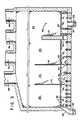
- FIG. 2 and 3 there is illustrated another embodiment of the invention wherein a modified ash vessel or burn-up cell 50 is combined with a number of fluidized bed cooling cells.
- the ash vessel 50 carries out the functions of classifying and carbon burn-up, but does not significantly cool the ash under treatment.
- ash fed into the fluidized bed 52 of ash vessel 50 is at a temperature in the range of about 1550 to 1650°F.
- the purpose of the fluidized cooling cells 60, 70 and 80, then, is to achieve a substantial decrease in the ash temperature.
- the temperature of the ash can be reduced to a level of about 300-400°F at which temperature the ash can be more easily handled by a conventional ash system.
- the air passing through the fluidized bed of ash in each cell can be conveyed back to the boiler from each cell at the combined temperature thus acting as a secondary air heater and recovering the heat from the ash and returning it to the boiler.
- the ash treatment vessel 50 of this embodiment has a submerged weir 54 provided in the dividing wall 51 of the ash treatment vessel at a level just below that of the highest row of tuyeres 35 to provide communication between the fluidized bed in the ash vessel and the fluidized bed of the adjacent cooling cell 60.
- the cooling cell 60 has a submerged weir 64 at a low position of wall 61 within the fluidized bed for communication with a second cooling cell 70.
- the cooling cell 70 has its own submerged weir 74 in wall 71 for communication with the last of the series of cooling cells 80.
- the cooling cell 80 has a port 88 through which the ash from the fluidized bed in cooling cell 80 can exit for disposal by operation of valve 89.
- the ash vessel 50 has a return conduit 46 for returning fine ash and hot gases to the boiler and each of the cooling cells has an exhaust conduct 66, 76, 86 for returning heated air to the boiler.
- the ash vessel 50 is provided with a discharge conduit 56 in the bottom thereof for withdrawing fluidized bed solids from the vessel through operation of valve 59 in conduit 56.
- cooling cells While three cooling cells have been shown in this embodiment, the precise number of cooling cells will depend upon the application and may be either more or less than that shown. Also, overflow weirs may be provided instead of the underflow weirs illustrated.
- the ash in the burn-up cell 50 is kept at a combustion temperature of 1550-1650°F in order to hum out the carbon in the ash emerging from the fluid bed combustor.
- the ash in the fluidized bed of the burn-up cell 50 passes into the first cooling cell 60 wherein it is cooled by the fluidizing air down to a temperature in the range of 900-1100°F.
- the second cooling cell 70 the temperature of the ash is reduced to the range of from 600-700°F and in the third cooling cell 80 the temperature of the ash is reduced to 300-400°F.
- the sensible heat that would otherwise have been lost in disposal of the hot ash is regained and typically decreases the ash temperature from 1600°F to 325°F representing approximately 5% in boiler efficiency.
- Reducing the carbon in the ash from 2.5-3% on exiting the boiler to less than .5% on exiting the ash cooler also gains over 2.5% in boiler efficiency by increasing the combustion efficiency.
- the combination of ash treatment vessel and coolers enables an efficiency gain of approximately 7.5% to be achieved. This is a significant gain in efficiency when burning poor grade fuels such as anthracite culm or coal colliery waste ("gob") because these fuels typically have a low calorific heat content in the range of 2900-3500 Btu/lb. Even with higher heat content fuels in the range of 3500-8500 Btu/lb significant gains in combustion and overall boiler efficiency can be made.
Landscapes
- Engineering & Computer Science (AREA)
- Chemical & Material Sciences (AREA)
- Combustion & Propulsion (AREA)
- Mechanical Engineering (AREA)
- General Engineering & Computer Science (AREA)
- Gasification And Melting Of Waste (AREA)
- Fluidized-Bed Combustion And Resonant Combustion (AREA)
- Incineration Of Waste (AREA)
Applications Claiming Priority (2)
| Application Number | Priority Date | Filing Date | Title |
|---|---|---|---|
| US341337 | 1989-04-21 | ||
| US07/341,337 US4969404A (en) | 1989-04-21 | 1989-04-21 | Ash classifier-cooler-combustor |
Publications (2)
| Publication Number | Publication Date |
|---|---|
| EP0393931A2 true EP0393931A2 (fr) | 1990-10-24 |
| EP0393931A3 EP0393931A3 (fr) | 1991-02-06 |
Family
ID=23337127
Family Applications (1)
| Application Number | Title | Priority Date | Filing Date |
|---|---|---|---|
| EP19900303965 Ceased EP0393931A3 (fr) | 1989-04-21 | 1990-04-11 | Système et procédé de traitement de cendres |
Country Status (6)
| Country | Link |
|---|---|
| US (1) | US4969404A (fr) |
| EP (1) | EP0393931A3 (fr) |
| JP (1) | JPH02293516A (fr) |
| AU (1) | AU628510B2 (fr) |
| CA (1) | CA2012642A1 (fr) |
| ZA (1) | ZA902284B (fr) |
Cited By (7)
| Publication number | Priority date | Publication date | Assignee | Title |
|---|---|---|---|---|
| DE4202895A1 (de) * | 1992-02-01 | 1993-08-05 | Schmidt Sche Heissdampf | Vorrichtung zum verbrennen kohlenstoffhaltiger brennstoffe in einer zirkulierenden wirbelschicht |
| EP0593229A1 (fr) * | 1992-10-16 | 1994-04-20 | Foster Wheeler Energy Corporation | Réacteur à lit fluidisé utilisant un système à chicanes et procédé pour sa mise en oeuvre |
| EP0595487A1 (fr) * | 1992-10-26 | 1994-05-04 | Foster Wheeler Energy Corporation | Réacteur à lit fluidisé avec refroidisseur à gaz de strippage et procédé de sa mise en oeuvre |
| US5510085A (en) * | 1992-10-26 | 1996-04-23 | Foster Wheeler Energy Corporation | Fluidized bed reactor including a stripper-cooler and method of operating same |
| DE19721206A1 (de) * | 1997-05-21 | 1998-11-26 | Babcock Kraftwerkstech Gmbh | Vorrichtung zur Entnahme und Kühlung von Bettasche aus einer Wirbelschichtfeuerung |
| RU2122681C1 (ru) * | 1994-08-17 | 1998-11-27 | Фостер Вилер Энергия Ой | Реакторное устройство с псевдоожиженным слоем и способ его осуществления |
| WO1999015829A1 (fr) * | 1997-09-22 | 1999-04-01 | Combustion Engineering, Inc. | Dispositif de refroidissement de cendres de lit fluidise |
Families Citing this family (6)
| Publication number | Priority date | Publication date | Assignee | Title |
|---|---|---|---|---|
| US5484476A (en) * | 1994-01-11 | 1996-01-16 | Electric Power Research Institute, Inc. | Method for preheating fly ash |
| DE19538711A1 (de) * | 1995-10-18 | 1997-04-30 | Sicowa Verfahrenstech | Verwendung von Leerzugasche aus steinkohlegefeuerten Anlagen |
| DE102005005796A1 (de) * | 2005-02-09 | 2006-08-17 | Applikations- Und Technikzentrum Für Energieverfahrens-, Umwelt- Und Strömungstechnik (Atz-Evus) | Verfahren und Vorrichtung zur thermochemischen Umsetzung eines Brennstoffs |
| CN104373934B (zh) * | 2014-11-03 | 2016-10-26 | 中国华能集团清洁能源技术研究院有限公司 | 循环流化床锅炉循环物料的制备储存与添加装置及方法 |
| CN105588112B (zh) * | 2016-02-24 | 2024-05-24 | 福建省南安市海特机械有限公司 | 一种生物颗粒燃烧机 |
| CN112696666A (zh) * | 2019-10-23 | 2021-04-23 | 北京中电长峰节能科技有限公司 | 一种循环流化床锅炉热渣能量及细颗粒回收系统 |
Family Cites Families (12)
| Publication number | Priority date | Publication date | Assignee | Title |
|---|---|---|---|---|
| FR1498034A (fr) * | 1966-10-28 | 1967-10-13 | Appareil pour l'incinération continue des déchets ou gadoues | |
| US4227488A (en) * | 1978-10-03 | 1980-10-14 | Foster Wheeler Energy Corporation | Fluidized bed unit including a cooling device for bed material |
| US4309194A (en) * | 1980-06-03 | 1982-01-05 | The United States Of America As Represented By The United States Department Of Energy | Particle withdrawal from fluidized bed systems |
| US4330502A (en) * | 1980-06-16 | 1982-05-18 | A. Ahlstrom Osakeyhtio | Fluidized bed reactor |
| GB2132500B (en) * | 1982-12-17 | 1986-06-04 | Coal Ind | Classification and recycling of fluidised bed material |
| US4664678A (en) * | 1983-11-25 | 1987-05-12 | Institute Of Gas Technology | Apparatus for controlling fluidized beds |
| SE447598B (sv) * | 1985-04-09 | 1986-11-24 | Goetaverken Energy Syst Ab | Forfarande for slutforbrenning av beddmaterial fran en forbrenningsanleggning med fluidiserad bedd |
| JPS62112984A (ja) * | 1985-11-13 | 1987-05-23 | 秩父セメント株式会社 | 粉末原料の流動焼成用仮焼装置 |
| US4693682A (en) * | 1986-05-12 | 1987-09-15 | Institute Of Gas Technology | Treatment of solids in fluidized bed burner |
| US4700636A (en) * | 1986-10-23 | 1987-10-20 | Dorr-Oliver Incorporated | Ash classifier |
| SE455726B (sv) * | 1986-12-11 | 1988-08-01 | Goetaverken Energy Ab | Forfarande vid reglering av kyleffekten i partikelkylare samt partikelkylare for pannor med cirkulerande fluidiserad bedd |
| US4777889A (en) * | 1987-05-22 | 1988-10-18 | Smith Richard D | Fluidized bed mass burner for solid waste |
-
1989
- 1989-04-21 US US07/341,337 patent/US4969404A/en not_active Expired - Fee Related
-
1990
- 1990-03-20 CA CA002012642A patent/CA2012642A1/fr not_active Abandoned
- 1990-03-23 ZA ZA902284A patent/ZA902284B/xx unknown
- 1990-04-09 AU AU52984/90A patent/AU628510B2/en not_active Ceased
- 1990-04-11 EP EP19900303965 patent/EP0393931A3/fr not_active Ceased
- 1990-04-17 JP JP2099461A patent/JPH02293516A/ja active Pending
Cited By (7)
| Publication number | Priority date | Publication date | Assignee | Title |
|---|---|---|---|---|
| DE4202895A1 (de) * | 1992-02-01 | 1993-08-05 | Schmidt Sche Heissdampf | Vorrichtung zum verbrennen kohlenstoffhaltiger brennstoffe in einer zirkulierenden wirbelschicht |
| EP0593229A1 (fr) * | 1992-10-16 | 1994-04-20 | Foster Wheeler Energy Corporation | Réacteur à lit fluidisé utilisant un système à chicanes et procédé pour sa mise en oeuvre |
| EP0595487A1 (fr) * | 1992-10-26 | 1994-05-04 | Foster Wheeler Energy Corporation | Réacteur à lit fluidisé avec refroidisseur à gaz de strippage et procédé de sa mise en oeuvre |
| US5510085A (en) * | 1992-10-26 | 1996-04-23 | Foster Wheeler Energy Corporation | Fluidized bed reactor including a stripper-cooler and method of operating same |
| RU2122681C1 (ru) * | 1994-08-17 | 1998-11-27 | Фостер Вилер Энергия Ой | Реакторное устройство с псевдоожиженным слоем и способ его осуществления |
| DE19721206A1 (de) * | 1997-05-21 | 1998-11-26 | Babcock Kraftwerkstech Gmbh | Vorrichtung zur Entnahme und Kühlung von Bettasche aus einer Wirbelschichtfeuerung |
| WO1999015829A1 (fr) * | 1997-09-22 | 1999-04-01 | Combustion Engineering, Inc. | Dispositif de refroidissement de cendres de lit fluidise |
Also Published As
| Publication number | Publication date |
|---|---|
| JPH02293516A (ja) | 1990-12-04 |
| EP0393931A3 (fr) | 1991-02-06 |
| US4969404A (en) | 1990-11-13 |
| ZA902284B (en) | 1991-11-27 |
| CA2012642A1 (fr) | 1990-10-21 |
| AU5298490A (en) | 1990-10-25 |
| AU628510B2 (en) | 1992-09-17 |
Similar Documents
| Publication | Publication Date | Title |
|---|---|---|
| CA1158421A (fr) | Reacteur a lit fluidise | |
| US5154732A (en) | Apparatus for gasifying or combusting solid carbonaceous | |
| US4684375A (en) | Method for gasifying a material using a circulating fluidized bed | |
| EP0384454B1 (fr) | Appareil pour gazéifier ou brûler des matériaux carbonés solides | |
| US4165717A (en) | Process for burning carbonaceous materials | |
| EP0740109B1 (fr) | Dispositif de combustion à lit fluidisé | |
| US4981111A (en) | Circulating fluidized bed combustion reactor with fly ash recycle | |
| US4969404A (en) | Ash classifier-cooler-combustor | |
| JP2657526B2 (ja) | 循環流動床系内の固形物分布を改善する方法 | |
| JPH0697083B2 (ja) | 一体型湾曲腕分離器を利用する循環流動床反応器 | |
| JPH07136494A (ja) | 反応器内の高温ガスを冷却する方法および装置 | |
| US4565139A (en) | Method and apparatus for obtaining energy | |
| EP0628345B1 (fr) | Méthode et dispositif pour traiter des gaz à température élevée | |
| US3119379A (en) | Apparatus for combustion of fuels | |
| EP0266944B1 (fr) | Dispositif de triage des cendres | |
| US4150632A (en) | Char separator | |
| EP0060044B1 (fr) | Combustion dans une couche fluidisée | |
| EP0545387A1 (fr) | Méthode et appareil pour la gaziéfication ou le combustible de matériaux carbonisés solides | |
| JP2651769B2 (ja) | 熱回収燃焼設備 | |
| US4335663A (en) | Thermal processing system | |
| US4298339A (en) | Method of heat treating a material | |
| JPS63187001A (ja) | 流動層熱回収装置およびその制御方法 | |
| US2850371A (en) | Fluid burning of finely divided sulfide ore concentrates | |
| JPH07332636A (ja) | 廃棄物焼却方法 |
Legal Events
| Date | Code | Title | Description |
|---|---|---|---|
| PUAI | Public reference made under article 153(3) epc to a published international application that has entered the european phase |
Free format text: ORIGINAL CODE: 0009012 |
|
| AK | Designated contracting states |
Kind code of ref document: A2 Designated state(s): AT BE CH DE DK ES FR GB GR IT LI LU NL SE |
|
| PUAL | Search report despatched |
Free format text: ORIGINAL CODE: 0009013 |
|
| AK | Designated contracting states |
Kind code of ref document: A3 Designated state(s): AT BE CH DE DK ES FR GB GR IT LI LU NL SE |
|
| 17P | Request for examination filed |
Effective date: 19910626 |
|
| 17Q | First examination report despatched |
Effective date: 19920401 |
|
| STAA | Information on the status of an ep patent application or granted ep patent |
Free format text: STATUS: THE APPLICATION HAS BEEN REFUSED |
|
| 18R | Application refused |
Effective date: 19930816 |