EP0393965A1 - Pneumatiques à carcasse radiale ayant des performances perfectionnées - Google Patents
Pneumatiques à carcasse radiale ayant des performances perfectionnées Download PDFInfo
- Publication number
- EP0393965A1 EP0393965A1 EP90304058A EP90304058A EP0393965A1 EP 0393965 A1 EP0393965 A1 EP 0393965A1 EP 90304058 A EP90304058 A EP 90304058A EP 90304058 A EP90304058 A EP 90304058A EP 0393965 A1 EP0393965 A1 EP 0393965A1
- Authority
- EP
- European Patent Office
- Prior art keywords
- carcass
- tire
- internal pressure
- line
- positions
- Prior art date
- Legal status (The legal status is an assumption and is not a legal conclusion. Google has not performed a legal analysis and makes no representation as to the accuracy of the status listed.)
- Granted
Links
- 239000011324 bead Substances 0.000 claims description 24
- 230000002787 reinforcement Effects 0.000 claims description 7
- 230000000875 corresponding effect Effects 0.000 description 9
- 230000001965 increasing effect Effects 0.000 description 4
- 238000005728 strengthening Methods 0.000 description 4
- 238000004073 vulcanization Methods 0.000 description 4
- 238000000034 method Methods 0.000 description 3
- 230000003014 reinforcing effect Effects 0.000 description 3
- 230000005540 biological transmission Effects 0.000 description 2
- 229910000831 Steel Inorganic materials 0.000 description 1
- 230000015556 catabolic process Effects 0.000 description 1
- 230000001276 controlling effect Effects 0.000 description 1
- 238000007796 conventional method Methods 0.000 description 1
- 238000006731 degradation reaction Methods 0.000 description 1
- 230000002708 enhancing effect Effects 0.000 description 1
- 230000002349 favourable effect Effects 0.000 description 1
- 239000010959 steel Substances 0.000 description 1
Images

Classifications
-
- B—PERFORMING OPERATIONS; TRANSPORTING
- B60—VEHICLES IN GENERAL
- B60C—VEHICLE TYRES; TYRE INFLATION; TYRE CHANGING; CONNECTING VALVES TO INFLATABLE ELASTIC BODIES IN GENERAL; DEVICES OR ARRANGEMENTS RELATED TO TYRES
- B60C3/00—Tyres characterised by the transverse section
- B60C3/04—Tyres characterised by the transverse section characterised by the relative dimensions of the section, e.g. low profile
-
- B—PERFORMING OPERATIONS; TRANSPORTING
- B60—VEHICLES IN GENERAL
- B60C—VEHICLE TYRES; TYRE INFLATION; TYRE CHANGING; CONNECTING VALVES TO INFLATABLE ELASTIC BODIES IN GENERAL; DEVICES OR ARRANGEMENTS RELATED TO TYRES
- B60C9/00—Reinforcements or ply arrangement of pneumatic tyres
- B60C9/02—Carcasses
- B60C9/0292—Carcass ply curvature
-
- Y—GENERAL TAGGING OF NEW TECHNOLOGICAL DEVELOPMENTS; GENERAL TAGGING OF CROSS-SECTIONAL TECHNOLOGIES SPANNING OVER SEVERAL SECTIONS OF THE IPC; TECHNICAL SUBJECTS COVERED BY FORMER USPC CROSS-REFERENCE ART COLLECTIONS [XRACs] AND DIGESTS
- Y10—TECHNICAL SUBJECTS COVERED BY FORMER USPC
- Y10T—TECHNICAL SUBJECTS COVERED BY FORMER US CLASSIFICATION
- Y10T152/00—Resilient tires and wheels
- Y10T152/10—Tires, resilient
- Y10T152/10495—Pneumatic tire or inner tube
- Y10T152/10855—Characterized by the carcass, carcass material, or physical arrangement of the carcass materials
Definitions
- This invention relates to pneumatic radial tires having improved running performances.
- the quantity of reinforcing member required and used for the strengthening of the reinforcement is generally increased to undesirably raise the cost.
- the ground contact area of the tread portion reduces to obstruct the transmission of necessary force, and consequently the steering performances, and traction and braking performances are degraded.
- the tire should be used under such an internal pressure as to hold a balance capable of accepting merits through the strengthening of the rigidity and demerits due to the degradation of the performances.
- the strengthening of the rigidity without causing the increase of the cost can not be achieved by the above conventional technique.
- an object of the invention to provide a novel pneumatic radial tire for automobiles, particularly passenger car which can advantageously realize the reinforcement of tread and bead portions in the tire without excessively using the reinforcing member over the conventionally adopted limit and increasing the internal pressure.
- a pneumatic radial tire having improved running performances comprising a carcass composed of at least one radial cord ply toroidally extending between a pair of bead portions as a casing reinforcement for sidewall portions and tread portion connecting to the bead portions, at least one cord ply of which carcass being wound around a bead core of the bead portion from inside of the tire toward outside thereof to form a turnup structure, and a belt composed of plural cord layers arranged along a crown portion of the carcass as a tread reinforcement, characterized in that when the tire is mounted onto a normal rim and inflated under an internal pressure corresponding to 5% of a normal internal pressure, a carcass line of the carcass in radial section of the tire at a self-posture under no load has at least two inflection points between positions A and C and/or between positions C and B in which A is a position corresponding to each end of the belt at its maximum width, B is a position corresponding to a
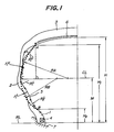
- heights H1, H2 and M of the positions A, B and C measured from a rim base line of the normal rim are within ranges of 0.80-1.0, 0.10-0.25 and 0.35-0.70 per a carcass maximum height H measured from the same rim base line, respectively.
- Fig. 1 a left-half section of the pneumatic radial tire for passenger car according to the invention in the radial direction thereof at a self-posture under no load when the tire is mounted onto a rim and inflated under an internal pressure corresponding to 5% of a normal internal pressure.
- This tire is symmetry with respect to the equator of the tire.
- numeral 1 is a bead portion
- numeral 2 a sidewall portion
- numeral 3 a tread portion
- numeral 4 a bead core
- numeral 5 a carcass
- numeral 6 a belt
- numeral 7 a normal rim closely fitted into the bead portion 1.
- the carcass 5 is comprised of at least one radial cord ply toroidally extending between the bead portions 1.
- the carcass is comprised of a single cord ply, but two or three plies may be used.
- at least one cord ply is wound around the bead core 4 from inside of the tire toward outside thereof to form a turnup structure according to the usual manner.
- an intersect point of a perpendicular line drawn from a widthwise end of a belt cord layer having a maximum width in the belt 6 toward a rim base line RL of the normal rim 7 with the carcass 5 is defined as a position A
- an intersect point of a perpendicular line drawn from the rim base line RL with the carcass 5 at a position corresponding to an end of the rim width of the normal rim 7 is defined as a position B
- a point corresponding to the maximum width of the carcass 5 is defined as a position C.
- a straight line passing through the position C and in parallel to the rim base line RL is CL
- a radius of an arc having a center on the straight line CL and passing through the positions A and C is RA
- a radius of an arc having a center on the straight line CL and passing through the positions B and C is RB.
- a mark X is an inflection point of the carcass line
- a mark ⁇ is a point most separated from a line segment connecting the position A or B to the inflection point X or a line segment connecting the adjoining inflection points X to each other.
- the above radii are preferable to be within ranges of the following equations (1)-(4) in relation with the radii RA and RB, respectively:
- the carcass line is adopted to have at least two inflection points each of between the positions A and C and between the positions B and C, whereby the running performances of the tire can be improved while using only the conventionally used members without requiring new addition or change to the structure of the tire as well as the reinforcing member for the tread and bead portions, so that the invention has great merits in the quality and productivity of the tire.
- the aforementioned peculiar profile of the carcass line is obtained by controlling a distribution of rubber gauge ranging from an inner wall of a mold to the carcass ply in a rotational axis direction of the tire in the building-up and vulcanization of the tire.
- the cord ply of the carcass 5 extending between the bead cores 4 is merely arranged along the inner shape of the tire according to the conventional building-up and vulcanization method.
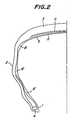
- an inner liner 8 having locally different thickness portions 8′ may be used as shown in Fig. 2.
- the change in the curvature of the carcass line may properly be controlled by forming continuous protrusions on a periphery of a bladder for vulcanization at positions corresponding to curvature changed portions of the carcass line.
- the carcass line according to the invention can properly be controlled without causing the variation or scattering in the productivity.
- the carcass line of the pneumatic radial tire in the radial section at the self-posture under an internal pressure corresponding to 5% of a normal internal pressure has at least two inflection points between the positions A and C and/or between the positions B and C.
- Fig. 3 carcass profiles having two inflection points each of between the positions A and C and between the positions B and C before and after the inflation under a normal internal pressure, in which a solid line is a carcass profile before the inflation and dotted lines are a carcass profile after the inflation.
- a portion of the carcass line having a center of curvature in an inside direction of the tire in adjacent to the position A deforms inward the tire without changing the curvature center
- a portion of the carcass line having a center of curvature in an outside direction of the tire deforms outward the tire with changing the curvature center into the inside of the tire.
- a portion of the carcass line having a center of curvature in an outside direction of the tire beneath the position C deforms outward the tire with changing the curvature center into the inside of the tire, while a portion of the carcass line having a center of curvature in an inside direction of the tire in adjacent to the position A deforms inward the tire without changing the curvature center.
- the strain produced along the carcass line due to the deformation of the tire is considered as follows.
- the carcass line In the portion wherein the curvature center changes from the outside of the tire toward the inside thereof, the carcass line has room against the deformation of the tire before the inflation under normal internal pressure, so that the strain produced along the carcass line after the inflation under normal internal pressure becomes small, and consequently the tension is small.
- the curvature center of the carcass line is held inside the tire before and after the inflation, if the carcass line is deformed inward during the inflation under normal internal pressure, the tension is small owing to the presence of room against the deformation, while if the carcass line is deformed outward during the inflation under normal internal pressure, the tension becomes large to a certain extent.
- the carcass line adjoining to the position A deforms inward with holding the curvature center at the inside of the tire through the inflation under normal internal pressure, so that the tension is small. Further, the position of curvature center in the carcass line located beneath the above carcass line portion changes from the outside of the tire toward the inside thereof, so that the tension is small.
- the belt tension increases by a quantity that the carcass tension is reduced from a balance between the internal pressure and the sum of carcass tension and belt tension.
- the curvature center in the carcass line located beneath the position C changes from the outside of the tire toward the inside thereof through the inflation under normal internal pressure, so that the tension is small.
- the carcass line located beneath the above carcass line portion deforms outward with holding the curvature center at the inside of the tire, so that the tension becomes not small. Therefore, a portion of the carcass tension reduced beneath the position C shifts to the lower portion of the carcass line from a balance between the internal pressure in the bead portion and the carcass tension to more enhance the tension near to the bead portion.
- the tension is ununiformly distributed through the carcass line, whereby large tension can be given to each of the tread portion requiring a large road gripping force and the bead portion requiring a large transmission force to the rim, and consequently the running performances are considerably improved.
- the portion 8′ of Fig. 2 is 1.7 to 8 times, preferably 2 to 4 times higher than the average thickness of the inner liner in order to sufficiently suppress the change of the casing line.
- the actual running test was made with respect to this tire together with the conventional tire having a carcass profile of natural equilibrium state.
- the running stability was evaluated by 10 point method, it was improved by 1.5 point in the tire according to the invention as compared with the conventional tire.
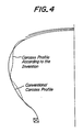
- a solid line is a natural equilibrium profile of the conventional tire before the inflation under normal internal pressure
- dotted lines are the carcass profile of the invention before the inflation under normal internal pressure.
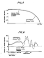
- the distribution of belt tension after the inflation under normal internal pressure in the tire according to the invention and the conventional tire is shown in Fig. 5, while the distribution of carcass ply tension after the inflation under normal internal pressure in the tire according to the invention and the conventional tire is shown in Fig. 6.
- the belt rigidity and the bead rigidity of the tire can advantageously be increased without enhancing the belt and bead reinforcements or increasing the internal pressure, which contributes to the improvement of the running performances in the tire.
Landscapes
- Engineering & Computer Science (AREA)
- Mechanical Engineering (AREA)
- Tires In General (AREA)
Applications Claiming Priority (2)
| Application Number | Priority Date | Filing Date | Title |
|---|---|---|---|
| JP95327/89 | 1989-04-17 | ||
| JP9532789 | 1989-04-17 |
Publications (2)
| Publication Number | Publication Date |
|---|---|
| EP0393965A1 true EP0393965A1 (fr) | 1990-10-24 |
| EP0393965B1 EP0393965B1 (fr) | 1992-12-30 |
Family
ID=14134636
Family Applications (1)
| Application Number | Title | Priority Date | Filing Date |
|---|---|---|---|
| EP90304058A Expired - Lifetime EP0393965B1 (fr) | 1989-04-17 | 1990-04-17 | Pneumatiques à carcasse radiale ayant des performances perfectionnées |
Country Status (6)
| Country | Link |
|---|---|
| US (2) | US5238039A (fr) |
| EP (1) | EP0393965B1 (fr) |
| KR (1) | KR960007022B1 (fr) |
| CA (1) | CA2014572C (fr) |
| DE (1) | DE69000684T2 (fr) |
| ES (1) | ES2038037T3 (fr) |
Cited By (4)
| Publication number | Priority date | Publication date | Assignee | Title |
|---|---|---|---|---|
| EP0413426A3 (en) * | 1989-08-15 | 1991-09-25 | Bridgestone Corporation | Pneumatic radial tires having improved bead portion durability |
| EP0486274A3 (en) * | 1990-11-16 | 1992-10-28 | Bridgestone Corporation | Pneumatic radial tires and a combination thereof |
| US5203934A (en) * | 1988-07-21 | 1993-04-20 | Bridgestone Corporation | Pneumatic radial tire with high durable bead portions |
| EP0502625A3 (en) * | 1991-03-05 | 1993-05-05 | Bridgestone Corporation | Pneumatic radial tires |
Families Citing this family (4)
| Publication number | Priority date | Publication date | Assignee | Title |
|---|---|---|---|---|
| CA2014572C (fr) * | 1989-04-17 | 1997-09-09 | Yukio Nakajima | Pneu radial gonflable caracterise par une amelioration du profil des flancs incurves |
| JPH09118108A (ja) * | 1995-06-28 | 1997-05-06 | Bridgestone Corp | ゴム補強用有機繊維コードおよびそれを用いた空気入りタイヤ |
| DE10221078A1 (de) * | 2002-05-11 | 2003-12-04 | Continental Ag | Pannenlauffähiger Fahrzeugluftreifen |
| US10071597B2 (en) * | 2013-09-10 | 2018-09-11 | Sumitomo Rubber Industries, Ltd. | Pneumatic tire |
Citations (5)
| Publication number | Priority date | Publication date | Assignee | Title |
|---|---|---|---|---|
| GB2070526A (en) * | 1980-02-29 | 1981-09-09 | Pirelli | Pneumatic tyres |
| JPS63154402A (ja) * | 1986-12-18 | 1988-06-27 | Sumitomo Rubber Ind Ltd | ラジアルタイヤ |
| EP0273558A2 (fr) * | 1986-12-25 | 1988-07-06 | Bridgestone Corporation | Pneumatique radial pour poids lourds |
| EP0314445A2 (fr) * | 1987-10-27 | 1989-05-03 | Sumitomo Rubber Industries Limited | Pneumatique de sécurité |
| EP0352140A2 (fr) * | 1988-07-21 | 1990-01-24 | Bridgestone Corporation | Pneumatique radial à parties de talons plus résistantes |
Family Cites Families (4)
| Publication number | Priority date | Publication date | Assignee | Title |
|---|---|---|---|---|
| USB361913I5 (fr) * | 1968-10-25 | |||
| FR2314059A1 (fr) * | 1975-06-12 | 1977-01-07 | Michelin & Cie | Enveloppes de pneumatiques sans armature |
| US5203934A (en) * | 1988-07-21 | 1993-04-20 | Bridgestone Corporation | Pneumatic radial tire with high durable bead portions |
| CA2014572C (fr) * | 1989-04-17 | 1997-09-09 | Yukio Nakajima | Pneu radial gonflable caracterise par une amelioration du profil des flancs incurves |
-
1990
- 1990-04-12 CA CA002014572A patent/CA2014572C/fr not_active Expired - Lifetime
- 1990-04-13 US US07/508,452 patent/US5238039A/en not_active Expired - Lifetime
- 1990-04-16 KR KR1019900005273A patent/KR960007022B1/ko not_active Expired - Lifetime
- 1990-04-17 ES ES199090304058T patent/ES2038037T3/es not_active Expired - Lifetime
- 1990-04-17 EP EP90304058A patent/EP0393965B1/fr not_active Expired - Lifetime
- 1990-04-17 DE DE9090304058T patent/DE69000684T2/de not_active Expired - Lifetime
-
1993
- 1993-03-23 US US08/035,883 patent/US5370169A/en not_active Expired - Lifetime
Patent Citations (5)
| Publication number | Priority date | Publication date | Assignee | Title |
|---|---|---|---|---|
| GB2070526A (en) * | 1980-02-29 | 1981-09-09 | Pirelli | Pneumatic tyres |
| JPS63154402A (ja) * | 1986-12-18 | 1988-06-27 | Sumitomo Rubber Ind Ltd | ラジアルタイヤ |
| EP0273558A2 (fr) * | 1986-12-25 | 1988-07-06 | Bridgestone Corporation | Pneumatique radial pour poids lourds |
| EP0314445A2 (fr) * | 1987-10-27 | 1989-05-03 | Sumitomo Rubber Industries Limited | Pneumatique de sécurité |
| EP0352140A2 (fr) * | 1988-07-21 | 1990-01-24 | Bridgestone Corporation | Pneumatique radial à parties de talons plus résistantes |
Cited By (5)
| Publication number | Priority date | Publication date | Assignee | Title |
|---|---|---|---|---|
| US5203934A (en) * | 1988-07-21 | 1993-04-20 | Bridgestone Corporation | Pneumatic radial tire with high durable bead portions |
| EP0413426A3 (en) * | 1989-08-15 | 1991-09-25 | Bridgestone Corporation | Pneumatic radial tires having improved bead portion durability |
| EP0486274A3 (en) * | 1990-11-16 | 1992-10-28 | Bridgestone Corporation | Pneumatic radial tires and a combination thereof |
| EP0502625A3 (en) * | 1991-03-05 | 1993-05-05 | Bridgestone Corporation | Pneumatic radial tires |
| US5403174A (en) * | 1991-03-05 | 1995-04-04 | Bridgestone Corporation | Pneumatic radial tires |
Also Published As
| Publication number | Publication date |
|---|---|
| US5370169A (en) | 1994-12-06 |
| CA2014572C (fr) | 1997-09-09 |
| KR900015956A (ko) | 1990-11-12 |
| KR960007022B1 (ko) | 1996-05-27 |
| EP0393965B1 (fr) | 1992-12-30 |
| ES2038037T3 (es) | 1993-07-01 |
| DE69000684D1 (de) | 1993-02-11 |
| CA2014572A1 (fr) | 1990-10-17 |
| US5238039A (en) | 1993-08-24 |
| DE69000684T2 (de) | 1993-04-29 |
Similar Documents
| Publication | Publication Date | Title |
|---|---|---|
| EP0605177B1 (fr) | Bandage pneumatique | |
| EP1167081A1 (fr) | Dispositif de roulage à plat pour véhicule automobile | |
| US6273162B1 (en) | Pneumatic tire with specified bead portion | |
| US4884610A (en) | Depressed radial tire | |
| US5200006A (en) | Pneumatic tire with uniform ground pressure at the tread face | |
| EP1201464B1 (fr) | Bandages pneumatiques radiaux | |
| JP4107961B2 (ja) | 空気入り安全タイヤ | |
| US6736178B2 (en) | Pneumatic tire with specified bead portion | |
| US5373884A (en) | Pneumatic tires with spaced sidewall recesses | |
| US6536495B1 (en) | Tread stiffening for two ply runflat tire | |
| US6719029B2 (en) | Tire wall gauges to optimize runflat tire ride comfort | |
| EP0393965B1 (fr) | Pneumatiques à carcasse radiale ayant des performances perfectionnées | |
| JP4270928B2 (ja) | 空気入りラジアルタイヤ | |
| JP4559624B2 (ja) | 広範な自動車のタイヤ用のトレッド補強手段 | |
| JP4104825B2 (ja) | ランフラットタイヤ用のトレッドおよびサイドウォール構造 | |
| JP2001121917A (ja) | 空気入りラジアルタイヤ | |
| EP0413426B1 (fr) | Bandage pneumatique radial ayant une meilleure durabilité des talons | |
| EP0486274B1 (fr) | Pneumatique radial | |
| EP0434014B1 (fr) | Pneumatique radial pour voitures | |
| JP6501600B2 (ja) | 空気入りタイヤ | |
| CA1214715A (fr) | Pneus radiaux pour voitures | |
| JP2604879B2 (ja) | 空気入りラジアルタイヤ | |
| EP1126984B1 (fr) | Renforcement de bande de roulement pour pneu a affaissement limite, a deux nappes | |
| EP1108567A1 (fr) | Pneumatique | |
| JPH04317802A (ja) | 空気入りラジアルタイヤ |
Legal Events
| Date | Code | Title | Description |
|---|---|---|---|
| PUAI | Public reference made under article 153(3) epc to a published international application that has entered the european phase |
Free format text: ORIGINAL CODE: 0009012 |
|
| AK | Designated contracting states |
Kind code of ref document: A1 Designated state(s): DE ES FR GB IT |
|
| 17P | Request for examination filed |
Effective date: 19900925 |
|
| 17Q | First examination report despatched |
Effective date: 19920513 |
|
| GRAA | (expected) grant |
Free format text: ORIGINAL CODE: 0009210 |
|
| AK | Designated contracting states |
Kind code of ref document: B1 Designated state(s): DE ES FR GB IT |
|
| ITF | It: translation for a ep patent filed | ||
| REF | Corresponds to: |
Ref document number: 69000684 Country of ref document: DE Date of ref document: 19930211 |
|
| ET | Fr: translation filed | ||
| REG | Reference to a national code |
Ref country code: ES Ref legal event code: FG2A Ref document number: 2038037 Country of ref document: ES Kind code of ref document: T3 |
|
| PLBE | No opposition filed within time limit |
Free format text: ORIGINAL CODE: 0009261 |
|
| STAA | Information on the status of an ep patent application or granted ep patent |
Free format text: STATUS: NO OPPOSITION FILED WITHIN TIME LIMIT |
|
| 26N | No opposition filed | ||
| REG | Reference to a national code |
Ref country code: GB Ref legal event code: IF02 |
|
| PGFP | Annual fee paid to national office [announced via postgrant information from national office to epo] |
Ref country code: ES Payment date: 20090513 Year of fee payment: 20 |
|
| PGFP | Annual fee paid to national office [announced via postgrant information from national office to epo] |
Ref country code: DE Payment date: 20090409 Year of fee payment: 20 Ref country code: FR Payment date: 20090417 Year of fee payment: 20 Ref country code: IT Payment date: 20090422 Year of fee payment: 20 |
|
| PGFP | Annual fee paid to national office [announced via postgrant information from national office to epo] |
Ref country code: GB Payment date: 20090415 Year of fee payment: 20 |
|
| REG | Reference to a national code |
Ref country code: GB Ref legal event code: PE20 Expiry date: 20100416 |
|
| REG | Reference to a national code |
Ref country code: ES Ref legal event code: FD2A Effective date: 20100419 |
|
| PG25 | Lapsed in a contracting state [announced via postgrant information from national office to epo] |
Ref country code: ES Free format text: LAPSE BECAUSE OF EXPIRATION OF PROTECTION Effective date: 20100419 |
|
| PG25 | Lapsed in a contracting state [announced via postgrant information from national office to epo] |
Ref country code: GB Free format text: LAPSE BECAUSE OF EXPIRATION OF PROTECTION Effective date: 20100416 |
|
| PG25 | Lapsed in a contracting state [announced via postgrant information from national office to epo] |
Ref country code: DE Free format text: LAPSE BECAUSE OF EXPIRATION OF PROTECTION Effective date: 20100417 |