EP0394380B1 - Fixation de securite pour ski - Google Patents
Fixation de securite pour ski Download PDFInfo
- Publication number
- EP0394380B1 EP0394380B1 EP89907127A EP89907127A EP0394380B1 EP 0394380 B1 EP0394380 B1 EP 0394380B1 EP 89907127 A EP89907127 A EP 89907127A EP 89907127 A EP89907127 A EP 89907127A EP 0394380 B1 EP0394380 B1 EP 0394380B1
- Authority
- EP
- European Patent Office
- Prior art keywords
- sole
- ski
- housing
- locking element
- sole plate
- Prior art date
- Legal status (The legal status is an assumption and is not a legal conclusion. Google has not performed a legal analysis and makes no representation as to the accuracy of the status listed.)
- Expired - Lifetime
Links
Images


Classifications
-
- A—HUMAN NECESSITIES
- A63—SPORTS; GAMES; AMUSEMENTS
- A63C—SKATES; SKIS; ROLLER SKATES; DESIGN OR LAYOUT OF COURTS, RINKS OR THE LIKE
- A63C9/00—Ski bindings
- A63C9/08—Ski bindings yieldable or self-releasing in the event of an accident, i.e. safety bindings
- A63C9/085—Ski bindings yieldable or self-releasing in the event of an accident, i.e. safety bindings with sole hold-downs, e.g. swingable
- A63C9/08557—Details of the release mechanism
- A63C9/08564—Details of the release mechanism using cam or slide surface
-
- A—HUMAN NECESSITIES
- A63—SPORTS; GAMES; AMUSEMENTS
- A63C—SKATES; SKIS; ROLLER SKATES; DESIGN OR LAYOUT OF COURTS, RINKS OR THE LIKE
- A63C9/00—Ski bindings
- A63C9/007—Systems preventing accumulation of forces on the binding when the ski is bending
-
- A—HUMAN NECESSITIES
- A63—SPORTS; GAMES; AMUSEMENTS
- A63C—SKATES; SKIS; ROLLER SKATES; DESIGN OR LAYOUT OF COURTS, RINKS OR THE LIKE
- A63C9/00—Ski bindings
- A63C9/08—Ski bindings yieldable or self-releasing in the event of an accident, i.e. safety bindings
- A63C9/081—Ski bindings yieldable or self-releasing in the event of an accident, i.e. safety bindings with swivel sole-plate
-
- A—HUMAN NECESSITIES
- A63—SPORTS; GAMES; AMUSEMENTS
- A63C—SKATES; SKIS; ROLLER SKATES; DESIGN OR LAYOUT OF COURTS, RINKS OR THE LIKE
- A63C9/00—Ski bindings
- A63C9/08—Ski bindings yieldable or self-releasing in the event of an accident, i.e. safety bindings
- A63C9/085—Ski bindings yieldable or self-releasing in the event of an accident, i.e. safety bindings with sole hold-downs, e.g. swingable
- A63C9/08507—Ski bindings yieldable or self-releasing in the event of an accident, i.e. safety bindings with sole hold-downs, e.g. swingable with a plurality of mobile jaws
- A63C9/08521—Ski bindings yieldable or self-releasing in the event of an accident, i.e. safety bindings with sole hold-downs, e.g. swingable with a plurality of mobile jaws pivoting about a vertical axis, e.g. side release
-
- A—HUMAN NECESSITIES
- A63—SPORTS; GAMES; AMUSEMENTS
- A63C—SKATES; SKIS; ROLLER SKATES; DESIGN OR LAYOUT OF COURTS, RINKS OR THE LIKE
- A63C7/00—Devices preventing skis from slipping back; Ski-stoppers or ski-brakes
- A63C7/10—Hinged stoppage blades attachable to the skis in such manner that these blades can be moved out of the operative position
- A63C7/1006—Ski-stoppers
- A63C7/1013—Ski-stoppers actuated by the boot
-
- A—HUMAN NECESSITIES
- A63—SPORTS; GAMES; AMUSEMENTS
- A63C—SKATES; SKIS; ROLLER SKATES; DESIGN OR LAYOUT OF COURTS, RINKS OR THE LIKE
- A63C9/00—Ski bindings
- A63C9/005—Ski bindings with means for adjusting the position of a shoe holder or of the complete binding relative to the ski
-
- A—HUMAN NECESSITIES
- A63—SPORTS; GAMES; AMUSEMENTS
- A63C—SKATES; SKIS; ROLLER SKATES; DESIGN OR LAYOUT OF COURTS, RINKS OR THE LIKE
- A63C9/00—Ski bindings
- A63C9/08—Ski bindings yieldable or self-releasing in the event of an accident, i.e. safety bindings
- A63C9/084—Ski bindings yieldable or self-releasing in the event of an accident, i.e. safety bindings with heel hold-downs, e.g. swingable
-
- A—HUMAN NECESSITIES
- A63—SPORTS; GAMES; AMUSEMENTS
- A63C—SKATES; SKIS; ROLLER SKATES; DESIGN OR LAYOUT OF COURTS, RINKS OR THE LIKE
- A63C9/00—Ski bindings
- A63C9/08—Ski bindings yieldable or self-releasing in the event of an accident, i.e. safety bindings
- A63C9/085—Ski bindings yieldable or self-releasing in the event of an accident, i.e. safety bindings with sole hold-downs, e.g. swingable
- A63C9/08557—Details of the release mechanism
- A63C9/08571—Details of the release mechanism using axis and lever
Definitions
- the invention relates to a safety ski binding according to the preamble of claim 1.
- the sole holders are designed as angle pieces which can be pivoted about a vertical axis, one leg of which holds the sole of the ski boot, while an angle lever is articulated on the other leg.
- the mutually directed ends of the angle levers are connected to one another in an articulated manner and acted upon by a leg spring in the closing direction of the ski binding.
- the free ends of the angle levers are facing forward.
- This known ski binding has the disadvantage that the toe consists of many individual parts that are movable relative to one another. On the one hand, this can cause friction forces that are difficult to control in many places, on the other hand, the production of a ski binding consisting of so many individual parts is also complex.
- a return spring separate from the release spring, which is attached in the heel holder and controls the plate movement, is required.
- this known ski binding in the event of a ski deflection due to uneven terrain, only a slight longitudinal compensation is possible before jamming occurs.
- the present invention has set itself the goal of avoiding the disadvantages mentioned and to make a ski binding of the type mentioned in its construction more compact. to reduce the number of individual components. Furthermore, tensioning of the ski boot sole or jamming of binding parts in the event of ski deflection should be reliably avoided.
- the object is achieved according to the invention by the characterizing features of claim 1.
- the arrangement of the rod-shaped control element in an exemption of the longitudinally displaceable housing reliably prevents the sole of the ski boot from becoming jammed or the binding base plate from jamming.
- a housing which can be displaced in the longitudinal direction of the ski is known per se from AT-PS 384.950.
- the embodiment according to the features of claim 2 enables a common movement of the locking element with the control element.
- the measure of claim 3 saves the use of additional components.
- the measure of claim 4 makes it easier for the binding fitter to assemble or adjust the length of the ski binding without time-consuming manipulations.
- the features of claim 5 ensure that the ski binding automatically returns to the entry-ready position after a safety release.
- the upper horizontal region of a support element extends essentially over the width of a front end region of the sole plate.
- the design according to the characterizing part of claim 8 allows the designer to design the pivoting point and pivoting range of the sole holder either.
- FIG. 1 shows the ski binding according to the invention in longitudinal section
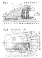
- FIG. 2 shows the front jaws according to FIG. 1 on a larger scale
- FIG. 3 shows a top view thereof, partially cut along the line III-III of FIG. 2
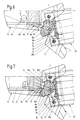
- FIG. 4 shows the front jaws with the sole plate partially pivoted
- FIG. 5 the front jaw at the trigger point, partially cut along the line VV of FIG. 2
- FIG. 6 the front jaw when the triggering has taken place
- FIG. 7 the front jaw during the return movement.
- front, rear, left and right refer to the position of the ski binding, i.e. front means towards the ski tip etc.
- FIG. 1 A complete safety ski binding to be described in more detail below can be seen in FIG.
- the parts shown with dash-dotted lines are not the subject of the invention and have only been shown for the sake of clarity.
- a base plate 3 for a toe 10 and a mounting plate 5 for a sole plate 20 pivotably mounted on a pivot 6 in a known manner are fastened by means of screws 2, which are only partially indicated.
- the sole plate 20 also carries a heel holder 30 and a ski brake 40, the known type are not a subject of the invention and are therefore not described in detail.
- the base plate 3 has guide rails 3a which extend in the longitudinal direction of the ski and project upwards on both sides.
- a housing 4 is mounted by means of its base 4a so as to be longitudinally displaceable but not removable.
- an exemption 4b is provided for parts of the toe piece 10 to be described later.
- the exemption 4b has stops 4c on its lateral edges.
- a guide groove 4h is cut out on the side facing the relief 4b.
- the guide groove 4h runs along a circular ring piece, the center line of which is drawn along a circle, the center point of which lies in the axis of the pivot pin 6.
- 4 through holes 4i are provided for the screws 2 in the housing.
- a transverse inner wall 4j of the exemption 4b is laterally provided with a control curve 4d.
- a front end region 20a of the sole plate 20 is designed as a bearing point for the sole holder 7 and a trigger mechanism to be described in more detail.
- the sole plate 20 has straps 20b extending forward at its front end region 20a.
- a vertical trim 20c extends in the central width region of the front end region 20a of the sole plate 20.
- a vertical section 20d is connected to the vertical section 20c.
- the sole plate 20 also has. guides 20e not described here on both sides for a rear sole plate part, not shown.
- a support member 20f is formed with the front end portion 20a of the sole plate 20 as a bearing unit 20g.
- a lower horizontal region 20h of the carrier element 20f extends partly under the sole plate 20, partly in front of it.
- a vertical region 20i which runs at least partially parallel to the vertical section 20v of the front end region 20a of the sole plate 20.
- the vertical region 20i of the carrier element 20f instructs. on both sides inclined contact surfaces 20n for the sole holder 7.
- An upper horizontal region 20j adjoining the vertical region 20i of the carrier element 20f extends essentially over the width of the front end region 20a of the sole plate 20.
- a slot 20k is provided, in which the horizontal section 20d of the front end region 20a of the sole plate 20 extends.
- the upper horizontal region 20j also has an upwardly projecting projection 20m which engages with play in the guide groove 4h of the housing 4.
- the upper horizontal region 20j is designed as a sole hold-down device 20o.
- a vertically running central axis 12 and two likewise vertically running sole holder bolts 11 are anchored in the bearing unit 20g.
- the sole holders 7 are articulated on the sole holder bolts 11.
- the sole holders 7 are equipped in their rear region in a known and therefore not described manner with contact surfaces for ski shoe coals.
- the sole holders 7 At their front end, the sole holders 7 have downward-facing pins 7a, the function of which will be described in more detail later.
- the sole holders 7 are curved in a plan view in their front region, each curve 7b ending in a locking stop 7c. At the end of the curve 7b facing away from the bolt stop 7c, a snap-on edge 7d is provided.
- a locking element 8 and a control element 9 which can be pivoted together with it are articulated on the axis 12.
- the locking element 8 is approximately heart-shaped in plan view and has arches 8a and converging curved surfaces 8b.
- the control element 9 is approximately rod-shaped and, viewed in the driving position of the ski binding, extends from the axis 12 to the front in the region of the longitudinal axis of the ski.
- the sole plate 20 is pivoted. It takes the locking element 8 and the control element 9 with it. As soon as the control element 9 has reached the stop 4c (see FIG. 4), it begins to pivot together with the locking element 8 about the axis 12. If the force exceeds the elasticity range of the ski binding, the sole plate 20 on the one hand and the unit consisting of the locking element 8 and the control element 9 on the other hand are pivoted further until the sole holder 7 leading in the pivoting direction is released with its snap edge 7d from the area of the arch 8a of the locking element 8 (see Fig. 5) and releases the ski boot, not shown here, without further effort.
Landscapes
- Footwear And Its Accessory, Manufacturing Method And Apparatuses (AREA)
Abstract
Claims (8)
Applications Claiming Priority (2)
| Application Number | Priority Date | Filing Date | Title |
|---|---|---|---|
| AT1720/88 | 1988-07-04 | ||
| AT0172088A AT390380B (de) | 1988-07-04 | 1988-07-04 | Sicherheitsskibindung |
Publications (2)
| Publication Number | Publication Date |
|---|---|
| EP0394380A1 EP0394380A1 (fr) | 1990-10-31 |
| EP0394380B1 true EP0394380B1 (fr) | 1992-05-13 |
Family
ID=3519547
Family Applications (1)
| Application Number | Title | Priority Date | Filing Date |
|---|---|---|---|
| EP89907127A Expired - Lifetime EP0394380B1 (fr) | 1988-07-04 | 1989-06-15 | Fixation de securite pour ski |
Country Status (5)
| Country | Link |
|---|---|
| US (1) | US5044657A (fr) |
| EP (1) | EP0394380B1 (fr) |
| JP (1) | JPH02502347A (fr) |
| AT (1) | AT390380B (fr) |
| WO (1) | WO1990000078A1 (fr) |
Families Citing this family (7)
| Publication number | Priority date | Publication date | Assignee | Title |
|---|---|---|---|---|
| US5299373A (en) * | 1989-11-24 | 1994-04-05 | Sandor Breiner | Hand-gun with moving cartridge chamber magazine |
| DE4022945A1 (de) * | 1990-03-29 | 1992-01-23 | Jungkind Roland | Sicherheitsskibindung mit verschwenkbarer sohlenplatte |
| US5626601A (en) * | 1995-10-27 | 1997-05-06 | Gary Gershony | Vascular sealing apparatus and method |
| EP0635287B1 (fr) * | 1993-07-21 | 1997-12-17 | HTM Sport- und Freizeitgeräte Gesellschaft m.b.H. | Mâchoire avant de fixation de ski |
| DE19518760A1 (de) * | 1995-05-22 | 1996-11-28 | Marker Deutschland Gmbh | Vorderbacken einer Skisicherheitsbindung |
| US7086662B2 (en) * | 2001-01-30 | 2006-08-08 | Trak Sports Usa, Inc. | Ski binding |
| FR2966747B1 (fr) * | 2010-10-29 | 2013-01-11 | Salomon Sas | Fixation de securite pour la pratique du ski. |
Family Cites Families (7)
| Publication number | Priority date | Publication date | Assignee | Title |
|---|---|---|---|---|
| DE2825876A1 (de) * | 1978-06-13 | 1980-01-03 | Gertsch Ernst | Sicherheitsskibindung |
| DE3102010A1 (de) * | 1981-01-22 | 1982-09-02 | Roland 8100 Garmisch-Partenkirchen Jungkind | "sicherheitsskibindung" |
| DE3515847C2 (de) * | 1985-05-02 | 1994-04-07 | Marker Deutschland Gmbh | Vorderbacken für Sicherheitsskibindungen |
| DE3539969C2 (de) * | 1985-11-11 | 1994-09-08 | Marker Deutschland Gmbh | Vorderbacken für Sicherheits-Skibindungen |
| AT384950B (de) * | 1986-06-06 | 1988-01-25 | Tyrolia Freizeitgeraete | Sicherheitsskibindung |
| AT385423B (de) * | 1986-08-22 | 1988-03-25 | Tyrolia Freizeitgeraete | Vorderbacken fuer sicherheitsskibindungen |
| DE8633619U1 (de) * | 1986-12-16 | 1988-04-14 | Marker Deutschland GmbH, 8100 Garmisch-Partenkirchen | Vorderbacken für Sicherheits-Skibindungen |
-
1988
- 1988-07-04 AT AT0172088A patent/AT390380B/de not_active IP Right Cessation
-
1989
- 1989-06-15 JP JP1506672A patent/JPH02502347A/ja active Pending
- 1989-06-15 US US07/466,350 patent/US5044657A/en not_active Expired - Fee Related
- 1989-06-15 WO PCT/EP1989/000670 patent/WO1990000078A1/fr not_active Ceased
- 1989-06-15 EP EP89907127A patent/EP0394380B1/fr not_active Expired - Lifetime
Also Published As
| Publication number | Publication date |
|---|---|
| EP0394380A1 (fr) | 1990-10-31 |
| US5044657A (en) | 1991-09-03 |
| AT390380B (de) | 1990-04-25 |
| ATA172088A (de) | 1989-10-15 |
| JPH02502347A (ja) | 1990-08-02 |
| WO1990000078A1 (fr) | 1990-01-11 |
Similar Documents
| Publication | Publication Date | Title |
|---|---|---|
| DE2756897A1 (de) | Sicherheitsskibindung | |
| DE1578751B2 (de) | Fersenbindung | |
| DE3031611C2 (de) | Backen einer Skibindung | |
| EP0259407B1 (fr) | Fixation de securite pour ski | |
| AT390380B (de) | Sicherheitsskibindung | |
| DE3143576A1 (de) | Backen, insbesondere vorderbacken, fuer sicherheitsskibindungen | |
| DE2213942C3 (de) | Sicherheits-Skibindung | |
| DE2604656A1 (de) | Vorrichtung zum automatischen anhalten eines vom skilaeufer geloesten skis | |
| DE3445760C2 (fr) | ||
| DE3342155C2 (de) | Sicherheitsskibindung | |
| CH646340A5 (de) | Sicherheitsskibindung. | |
| DE3030836C2 (fr) | ||
| DE2600858C3 (de) | Skisicherheitsbindung mit einer mit dem Schuh lösbar verbundenen Trittplatte | |
| DE4435960C1 (de) | Snowboardbindung | |
| DE3124853C2 (de) | Backen, insbesondere Vorderbacken für eine Auslöseskibindung | |
| EP0272317B1 (fr) | Fixation de securite pour ski | |
| CH636274A5 (de) | Sicherheitsskibindung. | |
| DE2432710C3 (de) | Vorderbacken einer Auslöseskibindung | |
| EP0113415B1 (fr) | Fixation de sécurité pour ski de fond | |
| AT390382B (de) | Vorderbacken fuer sicherheitsskibindungen | |
| EP0157091B1 (fr) | Soutien de talon | |
| EP0119518B1 (fr) | Fixation de sécurité pour ski | |
| DE2321816B2 (de) | Sicherheits-Skibindung mit einer Auslöseplatte | |
| DE2705661A1 (de) | Fersenhalter fuer skibindungen | |
| EP0254829B1 (fr) | Fixation de sécurité pour ski |
Legal Events
| Date | Code | Title | Description |
|---|---|---|---|
| PUAI | Public reference made under article 153(3) epc to a published international application that has entered the european phase |
Free format text: ORIGINAL CODE: 0009012 |
|
| 17P | Request for examination filed |
Effective date: 19900302 |
|
| AK | Designated contracting states |
Kind code of ref document: A1 Designated state(s): CH DE FR LI |
|
| 17Q | First examination report despatched |
Effective date: 19910731 |
|
| RAP1 | Party data changed (applicant data changed or rights of an application transferred) |
Owner name: TMC CORPORATION |
|
| GRAA | (expected) grant |
Free format text: ORIGINAL CODE: 0009210 |
|
| AK | Designated contracting states |
Kind code of ref document: B1 Designated state(s): CH DE FR LI |
|
| REF | Corresponds to: |
Ref document number: 58901430 Country of ref document: DE Date of ref document: 19920617 |
|
| K2C3 | Correction of patent specification (complete document) published |
Effective date: 19920513 |
|
| ET | Fr: translation filed | ||
| REG | Reference to a national code |
Ref country code: CH Ref legal event code: PUE Owner name: HTM SPORT- UND FREIZEITGERAETE GMBH |
|
| RAP2 | Party data changed (patent owner data changed or rights of a patent transferred) |
Owner name: HTM SPORT- UND FREIZEITGERAETE GESELLSCHAFT M.B.H. |
|
| REG | Reference to a national code |
Ref country code: FR Ref legal event code: TP |
|
| PLBE | No opposition filed within time limit |
Free format text: ORIGINAL CODE: 0009261 |
|
| STAA | Information on the status of an ep patent application or granted ep patent |
Free format text: STATUS: NO OPPOSITION FILED WITHIN TIME LIMIT |
|
| 26N | No opposition filed | ||
| REG | Reference to a national code |
Ref country code: CH Ref legal event code: PFA Free format text: HTM SPORT- UND FREIZEITGERAETE AKTIENGESELLSCHAFT |
|
| PGFP | Annual fee paid to national office [announced via postgrant information from national office to epo] |
Ref country code: DE Payment date: 19940423 Year of fee payment: 6 |
|
| PGFP | Annual fee paid to national office [announced via postgrant information from national office to epo] |
Ref country code: FR Payment date: 19940427 Year of fee payment: 6 |
|
| PGFP | Annual fee paid to national office [announced via postgrant information from national office to epo] |
Ref country code: CH Payment date: 19940614 Year of fee payment: 6 |
|
| REG | Reference to a national code |
Ref country code: FR Ref legal event code: CJ |
|
| PG25 | Lapsed in a contracting state [announced via postgrant information from national office to epo] |
Ref country code: LI Effective date: 19950630 Ref country code: CH Effective date: 19950630 |
|
| PG25 | Lapsed in a contracting state [announced via postgrant information from national office to epo] |
Ref country code: FR Effective date: 19960229 |
|
| REG | Reference to a national code |
Ref country code: CH Ref legal event code: PL |
|
| PG25 | Lapsed in a contracting state [announced via postgrant information from national office to epo] |
Ref country code: DE Effective date: 19960301 |
|
| REG | Reference to a national code |
Ref country code: FR Ref legal event code: ST |