EP0394528A1 - Synchronmaschine - Google Patents
Synchronmaschine Download PDFInfo
- Publication number
- EP0394528A1 EP0394528A1 EP89107630A EP89107630A EP0394528A1 EP 0394528 A1 EP0394528 A1 EP 0394528A1 EP 89107630 A EP89107630 A EP 89107630A EP 89107630 A EP89107630 A EP 89107630A EP 0394528 A1 EP0394528 A1 EP 0394528A1
- Authority
- EP
- European Patent Office
- Prior art keywords
- poles
- claw
- claw poles
- synchronous machine
- bzw
- Prior art date
- Legal status (The legal status is an assumption and is not a legal conclusion. Google has not performed a legal analysis and makes no representation as to the accuracy of the status listed.)
- Granted
Links
Images
Classifications
-
- H—ELECTRICITY
- H02—GENERATION; CONVERSION OR DISTRIBUTION OF ELECTRIC POWER
- H02K—DYNAMO-ELECTRIC MACHINES
- H02K21/00—Synchronous motors having permanent magnets; Synchronous generators having permanent magnets
- H02K21/12—Synchronous motors having permanent magnets; Synchronous generators having permanent magnets with stationary armatures and rotating magnets
- H02K21/14—Synchronous motors having permanent magnets; Synchronous generators having permanent magnets with stationary armatures and rotating magnets with magnets rotating within the armatures
-
- H—ELECTRICITY
- H02—GENERATION; CONVERSION OR DISTRIBUTION OF ELECTRIC POWER
- H02K—DYNAMO-ELECTRIC MACHINES
- H02K21/00—Synchronous motors having permanent magnets; Synchronous generators having permanent magnets
- H02K21/02—Details
- H02K21/04—Windings on magnets for additional excitation ; Windings and magnets for additional excitation
- H02K21/042—Windings on magnets for additional excitation ; Windings and magnets for additional excitation with permanent magnets and field winding both rotating
- H02K21/044—Rotor of the claw pole type
Definitions
- the invention relates to a synchronous machine according to the preamble of claim 1;
- Such synchronous machines are known in Klauenpolbauart as on-board generators in motor vehicles.
- Claw pole synchronous machines of the known type have a Klauenpolrotor with two Klauenpolsystemen with circumferentially toothed axially intermeshing claw poles and each end face the claw poles of one or the other system interconnecting Klauenpollini and at least one annular excitation coil whose exciter axis coincides with the axis of rotation of the rotor ,
- the claw pole carriers are magnetically coupled to one another within the exciter coil via a yoke yoke.
- a working winding is housed in a conventional manner in distributed over the circumference grooves of a stator lamination.
- a schleifringlose, thus wear-poorer and reliable and by the permanent magnets particularly advantageous usable inventive embodiment is characterized in that the excitation coil radially below the claw poles in an air gap fixed via a magnetically good conductive support member with a motor end face and the claw poles radially inside on a common non-magnetic Supported sleeve and are connected via the Klauenpolitati in front of the other engine front side with the rotor shaft.
- a working winding 13 is accommodated in grooves distributed over the circumference.
- a first end shield 11 is attached to the left end side and a second end shield 12 is attached to the right end side.
- the claw poles 41 and 51 of each claw pole system are interconnected by end claw pole connections 4 and 5, respectively.
- a fixed annular excitation coil 2 is provided, which is attached via an axially horrrekkendes, cylindrical magnetically good conductive holding part 8 on the first bearing plate 11.
- the fixed leads to the excitation coil 2 extend in an unspecified manner by axial holes of the holding part 8.
- the circumferentially alternately successive, axially nested claw poles 41 of the first Klauenpolsystems or Klauenpole 51 of the second Klauenpolsystems are fixed radially inside a non-magnetic sleeve 6 connected, so that the first claw pole system with the front side, the holding part 8 radially overlapping claw pole 4 of the claw poles 41 is mounted on the sleeve 6 on the fly.
- the claw poles 51 of the second claw pole system are connected to the rotor shaft 9 via their claw pole connection 51 as a carrier.
- the claw poles 41 ,.51 on the sleeve 6 are tangentially clamped between the non-magnetic clamping plates 7 in the vicinity of the air gap, which also serve as additional anti-rotation and as tangential adjusting the claw poles 41,51 and as Nutenver anyway.
- tangentially magnetized permanent magnets 3 are used between the tangential end faces of the claw poles 41,51 and radially below the clamping plates 7 and the radially inner covering sleeve 6 .
- the permanent magnets 3 are arranged or magnetized such that their magnetic voltage counteracts that of the current in the field winding. As a result, the stray flux between the claw poles 41 ,51 is avoided and a gain of the over the air gap in the laminated stator core. 1 achieved overflowing magnetic flux.
- the rotor yoke 14 of the claw pole system with the rest of the magnetic circuit in the rotor acts as a magnetic short circuit for the permanent magnets 3, so that the flux of the permanent magnets 3 then not through the stator air gap, but in the opposite direction to the electrically generated field exciter the rotor yoke closes.
Landscapes
- Engineering & Computer Science (AREA)
- Power Engineering (AREA)
- Synchronous Machinery (AREA)
- Iron Core Of Rotating Electric Machines (AREA)
Abstract
Description
- Die Erfindung bezieht sich auf eine Synchronmaschine gemäß Oberbegriff des Anspruchs 1; derartige Synchronmaschinen sind in Klauenpolbauart als Bordgeneratoren in Kraftfahrzeugen bekannt.
- Klauenpol-Synchronmaschinen der bekannten Bauart weisen einen Klauenpolrotor mit zwei Klauenpolsystemen mit über den Umfang verzahnt axial ineinandergreifenden Klauenpolen und jeweils stirnseitig die Klauenpole des einen bzw. des anderen Systems untereinander verbindendem Klauenpolträger und zumindest einer ringförmigen Erregerspule auf, deren Erregerachse mit der Drehachse des Rotors zusammenfällt. Die Klauenpolträger sind innerhalb der Erregerspule über ein Rückschlußjoch magnetisch miteinander gekoppelt. Im Stator ist eine Arbeitswicklung in an sich bekannter Weise in über den Umfang verteilten Nuten eines Statorblechpaketes untergebracht.
- Gemäß Aufgabe vorliegender Erfindung soll mit fertigungstechnisch einfachen Mitteln und bei kleiner Baugröße der Aufwand für die zu erbringende Erregerleistung gemindert werden.
- Die Lösung dieser Aufgabe gelingt bei einer Synchronmaschine der eingangs genannten Art durch die Lehre des Anspruchs 1; vorteilhafte Ausgestaltungen der Erfindung sind jeweils Gegenstand der Unteransprüche.
- In dem Maße, in dem die erfindungsgemäß vorgesehenen, zweckmäßigerweise mit tangential magnetisierenden Dauermagnete den Streufluß mindern und zum Luftspaltnutzfluß beitragen, kann der durch die Erregerspule aufzubringende elektrisch erregte Fluß reduziert und das dadurch entlastete Rotorjoch in seiner Baugröße verringert werden, wobei die Einstellbarkeit des Erregerfeldes durch die zusätzlichen Dauermagnete praktisch nicht eingeschränkt ist, da bei Abschaltung des die Erregerspule speisenden Erregerstromes der magnetische Kreis des Klauenpolrotors als magnetischer Kurzschluß für die Dauermagnete wirkt.
- Eine schleifringlose, dadurch verschleißärmere und betriebssichere sowie durch die Dauermagnete besonders vorteilhafte einsetzbare erfindungsgemäße Ausführung ist dadurch gekennzeichnet, daß die Erregerspule radial unterhalb der Klauenpole in einem Luftspaltabstand fest über ein magnetisch gut leitendes Tragteil mit der einen Motorstirnseite und die Klauenpole radial innen auf einer gemeinsamen unmagnetischen Hülse abgestützt und über die Klauenpolverbindung vor der anderen Motorstirnseite mit der Rotorwelle verbunden sind.
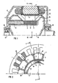
- Die Erfindung sowie weitere vorteilhafte Ausgestaltungen der Erfindung werden im folgenden anhand eines schematisch dargestellten Ausführungsbeispiels in der Zeichnung näher erläutert; darin zeigen:
- FIG 1 einen axialen Schnitt durch eine Synchronmaschine mit Klauenpolrotor und feststehender Erregerspule gemäß Schnittverlauf I-I in FIG 2,
- FIG 2 einen Schnitt durch die Synchronmaschine in FIG 1 gemäß Schnittverlauf II-II in FIG 1.
- In einem Statorblechpaket 1 ist in über den Umfang verteilten Nuten eine Arbeitswicklung 13 untergebracht. An dem Statorblechpaket 1 sind an der linken Stirnseite ein erstes Lagerschild 11 und an der rechten Stirnseite ein zweites Lagerschild 12 befestigt. In den Lagerschilden 12 ist über Lager 10 eine Rotorwelle 9 eines Klauenpolrotors mit den Klauenpolen 41 eines ersten Klauenpolsystems und den Klauenpolen 51 eines zweiten Klauenpolsystems drehbar gelagert. Die Klauenpole 41 bzw.51 jedes Klauenpolsystems sind untereinander durch stirnseitige Klauenpolverbindungen 4 bzw.5 verbunden.
- Zur elektrischen Erregung ist eine feststehende ringförmige Erregerspule 2 vorgesehen, die über ein sich axial erstrekkendes, zylindrisches magnetisch gut leitfähiges Halteteil 8 am ersten Lagerschild 11 befestigt ist. Die festen Zuleitungen zur Erregerspule 2 verlaufen in hier nicht näher dargestellter Weise durch axiale Bohrungen des Halteteil 8. Die über den Umfang wechselweise aufeinanderfolgenden, axial ineinandergesteckten Klauenpole 41 des ersten Klauenpolsystems bzw. Klauenpole 51 des zweiten Klauenpolsystems sind radial innen auf einer unmagnetischen Hülse 6 fest verbunden, derart daß das erste Klauenpolsystem mit den durch eine stirnseitige, das Halteteil 8 radial übergreifende Klauenpolverbindung 4 der Klauenpole 41 auf der Hülse 6 fliegend gelagert ist. Die Klauenpole 51 des zweiten Klauenpolsystems sind über ihre Klauenpolverbindung 51 als Träger mit der Rotorwelle 9 verbunden. Zur zusätzlichen Abstützung der Klauenpole 41 bzw.51 auf der Hülse 6 sind in der Nähe des Luftspaltes, zwischen diesen unmagnetische Klemmbleche 7 tangential zwischengeklemmt, die auch als zusätzliche Verdrehsicherung und als tangentiale Justiermittel der Klauenpole 41,51 und als Nutenverschlüsse dienen.
- Zwischen den tangentialen Stirnflächen der Klauenpole 41,51 und radial unter den Klemmblechen 7 und der radial innen abdeckenden Hülse 6 sind vorzugsweise tangential magnetisierte Dauermagnete 3 eingesetzt. Die Dauermagnete 3 sind derart angeordnet bzw. magnetisiert, daß ihre magnetische Spannung derjenigen vom Strom in der Erregerwicklung entgegenwirkt. Dadurch wird der Streufluß zwischen den Klauenpolen 41 bzw.51 vermieden und eine Verstärkung des über den Luftspalt in das Statorblechpaket 1 übertretende magnetischen Flusses erzielt. Bei Abschaltung der Erregerspule 2 wirkt das Rotorjoch 14 des Klauenpolsystems mit dem übrigen magnetischen Kreis im Rotor als magnetischer Kurzschluß für die Dauermagnete 3, derart daß sich der Fluß der Dauermagnete 3 dann nicht über den statorseitigen Luftspalt, sondern in entgegengesetzter Richtung zum elektrisch erzeugten Erregerfeld durch das Rotorjoch schließt.
Claims (5)
Priority Applications (2)
| Application Number | Priority Date | Filing Date | Title |
|---|---|---|---|
| DE8989107630T DE58903360D1 (de) | 1989-04-27 | 1989-04-27 | Synchronmaschine. |
| EP19890107630 EP0394528B1 (de) | 1989-04-27 | 1989-04-27 | Synchronmaschine |
Applications Claiming Priority (1)
| Application Number | Priority Date | Filing Date | Title |
|---|---|---|---|
| EP19890107630 EP0394528B1 (de) | 1989-04-27 | 1989-04-27 | Synchronmaschine |
Publications (2)
| Publication Number | Publication Date |
|---|---|
| EP0394528A1 true EP0394528A1 (de) | 1990-10-31 |
| EP0394528B1 EP0394528B1 (de) | 1993-01-20 |
Family
ID=8201299
Family Applications (1)
| Application Number | Title | Priority Date | Filing Date |
|---|---|---|---|
| EP19890107630 Expired - Lifetime EP0394528B1 (de) | 1989-04-27 | 1989-04-27 | Synchronmaschine |
Country Status (2)
| Country | Link |
|---|---|
| EP (1) | EP0394528B1 (de) |
| DE (1) | DE58903360D1 (de) |
Cited By (9)
| Publication number | Priority date | Publication date | Assignee | Title |
|---|---|---|---|---|
| DE4139843C1 (en) * | 1991-12-03 | 1993-06-24 | Albert 7880 Bad Saeckingen De Mutter | Dynamoelectric machine, esp. for car - has salient pole laminated rotor with permanent magnets between poles plus extra slip ring-fed excitation winding |
| DE29507990U1 (de) * | 1995-05-15 | 1996-03-14 | Siemens AG, 80333 München | Synchronmaschine in Schenkel- bzw. Klauenpolbauart |
| EP0932245A1 (de) * | 1998-01-26 | 1999-07-28 | Valeo Equipements Electriques Moteur | Elektrische Maschine mit doppelter Erregung, und insbesondere Fahrzeuggenerator |
| DE102007032141A1 (de) * | 2007-06-30 | 2009-01-02 | Robert Bosch Gmbh | Elektrische Maschine |
| US7604385B2 (en) | 2003-10-31 | 2009-10-20 | Valeo Vision | Lighting module for a vehicle headlight |
| CN102299598A (zh) * | 2011-09-05 | 2011-12-28 | 青岛敏深风电科技有限公司 | 电励磁与复合励磁的风力发电机 |
| EP2771965B1 (de) | 2011-10-28 | 2016-12-14 | Robert Bosch GmbH | Elektrische maschine, insbesondere wechselstromgenerator |
| EP2584682A3 (de) * | 2011-10-19 | 2017-08-16 | Robert Bosch Gmbh | Elektrische Maschine sowie Verwendung einer elektrischen Maschine |
| CN107546874A (zh) * | 2016-06-29 | 2018-01-05 | 上海茂昂智能科技股份有限公司 | 一种低启动式发电机低启动式发电机 |
Families Citing this family (7)
| Publication number | Priority date | Publication date | Assignee | Title |
|---|---|---|---|---|
| GB2247362B (en) * | 1990-08-24 | 1994-09-21 | Carl Erik Stille | Excitation arrangment for a homopolar machine |
| US5793144A (en) * | 1993-08-30 | 1998-08-11 | Nippondenso Co., Ltd. | Rotor for a rotating electric machine |
| JP3446313B2 (ja) * | 1993-08-30 | 2003-09-16 | 株式会社デンソー | 回転電機の回転子 |
| EP0723330B1 (de) | 1995-01-23 | 1998-01-07 | Siemens Aktiengesellschaft | Synchronmaschine in Schenkelpolbauart |
| JPH09163700A (ja) * | 1995-12-08 | 1997-06-20 | Mitsubishi Electric Corp | 交流発電機 |
| DE19711750A1 (de) | 1997-03-21 | 1998-10-08 | Daimler Benz Ag | Klauenpolmaschine |
| DE102011008076A1 (de) * | 2011-01-07 | 2012-02-23 | Entrak Energie- Und Antriebstechnik Gmbh & Co. Kg | Maschinenbauteil in Form eines Rotors oder Stators für eine elektrische Maschine und elektrische Maschine |
Citations (3)
| Publication number | Priority date | Publication date | Assignee | Title |
|---|---|---|---|---|
| DE1488353A1 (de) * | 1965-07-15 | 1969-06-26 | Siemens Ag | Permanentmagneterregte elektrische Maschine |
| DE2948980A1 (de) * | 1978-12-06 | 1980-06-26 | Magneti Marelli Spa | Buerstenloser dynamo, insbesondere fuer kraftfahrzeuge |
| FR2582164A1 (fr) * | 1985-05-20 | 1986-11-21 | Tecumseh Products Co | Alternateur-compresseur a excitation par aimant permanent et a commande en courant continu |
-
1989
- 1989-04-27 EP EP19890107630 patent/EP0394528B1/de not_active Expired - Lifetime
- 1989-04-27 DE DE8989107630T patent/DE58903360D1/de not_active Expired - Fee Related
Patent Citations (3)
| Publication number | Priority date | Publication date | Assignee | Title |
|---|---|---|---|---|
| DE1488353A1 (de) * | 1965-07-15 | 1969-06-26 | Siemens Ag | Permanentmagneterregte elektrische Maschine |
| DE2948980A1 (de) * | 1978-12-06 | 1980-06-26 | Magneti Marelli Spa | Buerstenloser dynamo, insbesondere fuer kraftfahrzeuge |
| FR2582164A1 (fr) * | 1985-05-20 | 1986-11-21 | Tecumseh Products Co | Alternateur-compresseur a excitation par aimant permanent et a commande en courant continu |
Cited By (13)
| Publication number | Priority date | Publication date | Assignee | Title |
|---|---|---|---|---|
| DE4139843C2 (de) * | 1991-12-03 | 1998-12-24 | Albert Mutter | Elektrische Maschine und deren Anwendung zum Fahrzeugbetrieb |
| DE4139843C1 (en) * | 1991-12-03 | 1993-06-24 | Albert 7880 Bad Saeckingen De Mutter | Dynamoelectric machine, esp. for car - has salient pole laminated rotor with permanent magnets between poles plus extra slip ring-fed excitation winding |
| DE29507990U1 (de) * | 1995-05-15 | 1996-03-14 | Siemens AG, 80333 München | Synchronmaschine in Schenkel- bzw. Klauenpolbauart |
| EP0932245A1 (de) * | 1998-01-26 | 1999-07-28 | Valeo Equipements Electriques Moteur | Elektrische Maschine mit doppelter Erregung, und insbesondere Fahrzeuggenerator |
| FR2774228A1 (fr) * | 1998-01-26 | 1999-07-30 | Valeo Equip Electr Moteur | Machine electrique a double excitation, et notamment alternateur de vehicule automobile |
| CN1089964C (zh) * | 1998-01-26 | 2002-08-28 | 瓦莱奥电机设备公司 | 双激励电机、尤其是汽车交流发电机 |
| US7604385B2 (en) | 2003-10-31 | 2009-10-20 | Valeo Vision | Lighting module for a vehicle headlight |
| DE102007032141A1 (de) * | 2007-06-30 | 2009-01-02 | Robert Bosch Gmbh | Elektrische Maschine |
| CN102299598A (zh) * | 2011-09-05 | 2011-12-28 | 青岛敏深风电科技有限公司 | 电励磁与复合励磁的风力发电机 |
| EP2584682A3 (de) * | 2011-10-19 | 2017-08-16 | Robert Bosch Gmbh | Elektrische Maschine sowie Verwendung einer elektrischen Maschine |
| EP2771965B1 (de) | 2011-10-28 | 2016-12-14 | Robert Bosch GmbH | Elektrische maschine, insbesondere wechselstromgenerator |
| EP2771965B2 (de) † | 2011-10-28 | 2020-01-08 | SEG Automotive Germany GmbH | Elektrische maschine, insbesondere wechselstromgenerator |
| CN107546874A (zh) * | 2016-06-29 | 2018-01-05 | 上海茂昂智能科技股份有限公司 | 一种低启动式发电机低启动式发电机 |
Also Published As
| Publication number | Publication date |
|---|---|
| EP0394528B1 (de) | 1993-01-20 |
| DE58903360D1 (de) | 1993-03-04 |
Similar Documents
| Publication | Publication Date | Title |
|---|---|---|
| DE3877845T2 (de) | Buerstenloser gleichstrommotor. | |
| DE112010003859B4 (de) | Drehmotor vom Lundell-Typ | |
| EP0394528A1 (de) | Synchronmaschine | |
| EP0729216A3 (de) | Hybriderregte Synchronmaschine | |
| DE102019206460B3 (de) | Drehende Mehrphasen-Transversalflussmaschine | |
| DE69107941T2 (de) | Bürstenloser Motor. | |
| EP0394527A1 (de) | Heteropolar erregte Synchronmaschine | |
| EP2210334B1 (de) | Permanent erregte elektrische maschine | |
| WO2010063546A1 (de) | Hybriderregte elektrische maschine mit polumschaltbarem rotor | |
| DE3122049A1 (de) | Kollektorloser gleichstromaussenlaeufermotor | |
| EP2319164B1 (de) | Rotor für eine elektrische maschine mit reduziertem rastmoment | |
| DE3844074C2 (de) | ||
| DE2548313A1 (de) | Elektrische maschine mit klauenpolen | |
| DE8905353U1 (de) | Synchronmaschine | |
| DE102008041605B4 (de) | Hybriderregte elektrische Maschine | |
| DE1488053B2 (de) | Rotierende elektrische gleichstrommaschine fuer niedrige spannungen und grosse stromstaerken | |
| EP1443639A1 (de) | Rotierender Erreger für grosse Ströme | |
| EP1231703B1 (de) | Unipolar-Maschine | |
| EP0501521A1 (de) | Bürstenloser Gleichstrommotor für niedrige Drehzahlen | |
| EP1075077B1 (de) | Verfahren zur Magnetisierung von in einem Rückschlussgehäuse gehaltenen Polschuhen eines über Bürsten gespeisten permanenterregten Kommutatormotors und Vorrichtung zur Durchführung des Verfahrens | |
| DE3213263C2 (de) | Einphasenschrittmotor | |
| EP0664934B1 (de) | Nach dem reluktanz-prinzip arbeitender motor und/oder generator | |
| DE1488053C (de) | Rotierende elektrische Gleichstrommaschine für niedrige Spannungen und große Stromstärken | |
| DE102019129782B4 (de) | Multipol-GENERATOR mit Gesamtmagnetfluss umschließenden Spulen | |
| DE2814420A1 (de) | Magnetgenerator fuer wechselstrom |
Legal Events
| Date | Code | Title | Description |
|---|---|---|---|
| PUAI | Public reference made under article 153(3) epc to a published international application that has entered the european phase |
Free format text: ORIGINAL CODE: 0009012 |
|
| 17P | Request for examination filed |
Effective date: 19900226 |
|
| AK | Designated contracting states |
Kind code of ref document: A1 Designated state(s): DE IT |
|
| 17Q | First examination report despatched |
Effective date: 19920624 |
|
| GRAA | (expected) grant |
Free format text: ORIGINAL CODE: 0009210 |
|
| AK | Designated contracting states |
Kind code of ref document: B1 Designated state(s): DE IT |
|
| REF | Corresponds to: |
Ref document number: 58903360 Country of ref document: DE Date of ref document: 19930304 |
|
| ITF | It: translation for a ep patent filed | ||
| PLBE | No opposition filed within time limit |
Free format text: ORIGINAL CODE: 0009261 |
|
| STAA | Information on the status of an ep patent application or granted ep patent |
Free format text: STATUS: NO OPPOSITION FILED WITHIN TIME LIMIT |
|
| 26N | No opposition filed | ||
| PG25 | Lapsed in a contracting state [announced via postgrant information from national office to epo] |
Ref country code: IT Free format text: LAPSE BECAUSE OF NON-PAYMENT OF DUE FEES;WARNING: LAPSES OF ITALIAN PATENTS WITH EFFECTIVE DATE BEFORE 2007 MAY HAVE OCCURRED AT ANY TIME BEFORE 2007. THE CORRECT EFFECTIVE DATE MAY BE DIFFERENT FROM THE ONE RECORDED. Effective date: 20050427 |
|
| PGFP | Annual fee paid to national office [announced via postgrant information from national office to epo] |
Ref country code: DE Payment date: 20060619 Year of fee payment: 18 |
|
| PG25 | Lapsed in a contracting state [announced via postgrant information from national office to epo] |
Ref country code: DE Free format text: LAPSE BECAUSE OF NON-PAYMENT OF DUE FEES Effective date: 20071101 |