EP0394576B1 - Druckerpresse - Google Patents
Druckerpresse Download PDFInfo
- Publication number
- EP0394576B1 EP0394576B1 EP89304337A EP89304337A EP0394576B1 EP 0394576 B1 EP0394576 B1 EP 0394576B1 EP 89304337 A EP89304337 A EP 89304337A EP 89304337 A EP89304337 A EP 89304337A EP 0394576 B1 EP0394576 B1 EP 0394576B1
- Authority
- EP
- European Patent Office
- Prior art keywords
- printing
- web
- image
- cylinder
- press
- Prior art date
- Legal status (The legal status is an assumption and is not a legal conclusion. Google has not performed a legal analysis and makes no representation as to the accuracy of the status listed.)
- Revoked
Links
- 238000007639 printing Methods 0.000 title claims description 96
- 238000000034 method Methods 0.000 claims description 22
- 239000000463 material Substances 0.000 claims description 9
- 239000003086 colorant Substances 0.000 claims description 5
- 238000012546 transfer Methods 0.000 claims description 5
- 238000012544 monitoring process Methods 0.000 claims description 2
- 238000004590 computer program Methods 0.000 claims 1
- 238000007599 discharging Methods 0.000 claims 1
- 230000000737 periodic effect Effects 0.000 claims 1
- 239000000843 powder Substances 0.000 description 7
- 238000004519 manufacturing process Methods 0.000 description 6
- 238000005516 engineering process Methods 0.000 description 3
- 230000008569 process Effects 0.000 description 3
- 238000010586 diagram Methods 0.000 description 2
- 238000007648 laser printing Methods 0.000 description 2
- 239000002245 particle Substances 0.000 description 2
- 230000004075 alteration Effects 0.000 description 1
- XAGFODPZIPBFFR-UHFFFAOYSA-N aluminium Chemical compound [Al] XAGFODPZIPBFFR-UHFFFAOYSA-N 0.000 description 1
- 229910052782 aluminium Inorganic materials 0.000 description 1
- 230000006835 compression Effects 0.000 description 1
- 238000007906 compression Methods 0.000 description 1
- 238000011161 development Methods 0.000 description 1
- 238000010438 heat treatment Methods 0.000 description 1
- 238000009434 installation Methods 0.000 description 1
- 239000011159 matrix material Substances 0.000 description 1
- 230000007246 mechanism Effects 0.000 description 1
- 239000000203 mixture Substances 0.000 description 1
- 238000012545 processing Methods 0.000 description 1
- 230000005855 radiation Effects 0.000 description 1
- 230000004044 response Effects 0.000 description 1
- 238000012163 sequencing technique Methods 0.000 description 1
- 239000000126 substance Substances 0.000 description 1
- 239000002699 waste material Substances 0.000 description 1
Images

Classifications
-
- G—PHYSICS
- G03—PHOTOGRAPHY; CINEMATOGRAPHY; ANALOGOUS TECHNIQUES USING WAVES OTHER THAN OPTICAL WAVES; ELECTROGRAPHY; HOLOGRAPHY
- G03G—ELECTROGRAPHY; ELECTROPHOTOGRAPHY; MAGNETOGRAPHY
- G03G15/00—Apparatus for electrographic processes using a charge pattern
- G03G15/65—Apparatus which relate to the handling of copy material
- G03G15/6517—Apparatus for continuous web copy material of plain paper, e.g. supply rolls; Roll holders therefor
- G03G15/652—Feeding a copy material originating from a continuous web roll
-
- G—PHYSICS
- G03—PHOTOGRAPHY; CINEMATOGRAPHY; ANALOGOUS TECHNIQUES USING WAVES OTHER THAN OPTICAL WAVES; ELECTROGRAPHY; HOLOGRAPHY
- G03G—ELECTROGRAPHY; ELECTROPHOTOGRAPHY; MAGNETOGRAPHY
- G03G15/00—Apparatus for electrographic processes using a charge pattern
- G03G15/01—Apparatus for electrographic processes using a charge pattern for producing multicoloured copies
- G03G15/0142—Structure of complete machines
- G03G15/0178—Structure of complete machines using more than one reusable electrographic recording member, e.g. one for every monocolour image
- G03G15/0194—Structure of complete machines using more than one reusable electrographic recording member, e.g. one for every monocolour image primary transfer to the final recording medium
-
- G—PHYSICS
- G03—PHOTOGRAPHY; CINEMATOGRAPHY; ANALOGOUS TECHNIQUES USING WAVES OTHER THAN OPTICAL WAVES; ELECTROGRAPHY; HOLOGRAPHY
- G03G—ELECTROGRAPHY; ELECTROPHOTOGRAPHY; MAGNETOGRAPHY
- G03G15/00—Apparatus for electrographic processes using a charge pattern
- G03G15/04—Apparatus for electrographic processes using a charge pattern for exposing, i.e. imagewise exposure by optically projecting the original image on a photoconductive recording material
- G03G15/04036—Details of illuminating systems, e.g. lamps, reflectors
- G03G15/04045—Details of illuminating systems, e.g. lamps, reflectors for exposing image information provided otherwise than by directly projecting the original image onto the photoconductive recording material, e.g. digital copiers
- G03G15/04072—Details of illuminating systems, e.g. lamps, reflectors for exposing image information provided otherwise than by directly projecting the original image onto the photoconductive recording material, e.g. digital copiers by laser
-
- G—PHYSICS
- G03—PHOTOGRAPHY; CINEMATOGRAPHY; ANALOGOUS TECHNIQUES USING WAVES OTHER THAN OPTICAL WAVES; ELECTROGRAPHY; HOLOGRAPHY
- G03G—ELECTROGRAPHY; ELECTROPHOTOGRAPHY; MAGNETOGRAPHY
- G03G15/00—Apparatus for electrographic processes using a charge pattern
- G03G15/22—Apparatus for electrographic processes using a charge pattern involving the combination of more than one step according to groups G03G13/02 - G03G13/20
- G03G15/32—Apparatus for electrographic processes using a charge pattern involving the combination of more than one step according to groups G03G13/02 - G03G13/20 in which the charge pattern is formed dotwise, e.g. by a thermal head
- G03G15/326—Apparatus for electrographic processes using a charge pattern involving the combination of more than one step according to groups G03G13/02 - G03G13/20 in which the charge pattern is formed dotwise, e.g. by a thermal head by application of light, e.g. using a LED array
-
- G—PHYSICS
- G03—PHOTOGRAPHY; CINEMATOGRAPHY; ANALOGOUS TECHNIQUES USING WAVES OTHER THAN OPTICAL WAVES; ELECTROGRAPHY; HOLOGRAPHY
- G03G—ELECTROGRAPHY; ELECTROPHOTOGRAPHY; MAGNETOGRAPHY
- G03G2215/00—Apparatus for electrophotographic processes
- G03G2215/00362—Apparatus for electrophotographic processes relating to the copy medium handling
- G03G2215/00367—The feeding path segment where particular handling of the copy medium occurs, segments being adjacent and non-overlapping. Each segment is identified by the most downstream point in the segment, so that for instance the segment labelled "Fixing device" is referring to the path between the "Transfer device" and the "Fixing device"
- G03G2215/00371—General use over the entire feeding path
-
- G—PHYSICS
- G03—PHOTOGRAPHY; CINEMATOGRAPHY; ANALOGOUS TECHNIQUES USING WAVES OTHER THAN OPTICAL WAVES; ELECTROGRAPHY; HOLOGRAPHY
- G03G—ELECTROGRAPHY; ELECTROPHOTOGRAPHY; MAGNETOGRAPHY
- G03G2215/00—Apparatus for electrophotographic processes
- G03G2215/00362—Apparatus for electrophotographic processes relating to the copy medium handling
- G03G2215/00367—The feeding path segment where particular handling of the copy medium occurs, segments being adjacent and non-overlapping. Each segment is identified by the most downstream point in the segment, so that for instance the segment labelled "Fixing device" is referring to the path between the "Transfer device" and the "Fixing device"
- G03G2215/00405—Registration device
-
- G—PHYSICS
- G03—PHOTOGRAPHY; CINEMATOGRAPHY; ANALOGOUS TECHNIQUES USING WAVES OTHER THAN OPTICAL WAVES; ELECTROGRAPHY; HOLOGRAPHY
- G03G—ELECTROGRAPHY; ELECTROPHOTOGRAPHY; MAGNETOGRAPHY
- G03G2215/00—Apparatus for electrophotographic processes
- G03G2215/00362—Apparatus for electrophotographic processes relating to the copy medium handling
- G03G2215/00443—Copy medium
- G03G2215/00451—Paper
-
- G—PHYSICS
- G03—PHOTOGRAPHY; CINEMATOGRAPHY; ANALOGOUS TECHNIQUES USING WAVES OTHER THAN OPTICAL WAVES; ELECTROGRAPHY; HOLOGRAPHY
- G03G—ELECTROGRAPHY; ELECTROPHOTOGRAPHY; MAGNETOGRAPHY
- G03G2215/00—Apparatus for electrophotographic processes
- G03G2215/00362—Apparatus for electrophotographic processes relating to the copy medium handling
- G03G2215/00443—Copy medium
- G03G2215/00451—Paper
- G03G2215/00455—Continuous web, i.e. roll
-
- G—PHYSICS
- G03—PHOTOGRAPHY; CINEMATOGRAPHY; ANALOGOUS TECHNIQUES USING WAVES OTHER THAN OPTICAL WAVES; ELECTROGRAPHY; HOLOGRAPHY
- G03G—ELECTROGRAPHY; ELECTROPHOTOGRAPHY; MAGNETOGRAPHY
- G03G2215/00—Apparatus for electrophotographic processes
- G03G2215/00362—Apparatus for electrophotographic processes relating to the copy medium handling
- G03G2215/00535—Stable handling of copy medium
- G03G2215/00603—Control of other part of the apparatus according to the state of copy medium feeding
-
- G—PHYSICS
- G03—PHOTOGRAPHY; CINEMATOGRAPHY; ANALOGOUS TECHNIQUES USING WAVES OTHER THAN OPTICAL WAVES; ELECTROGRAPHY; HOLOGRAPHY
- G03G—ELECTROGRAPHY; ELECTROPHOTOGRAPHY; MAGNETOGRAPHY
- G03G2215/00—Apparatus for electrophotographic processes
- G03G2215/00362—Apparatus for electrophotographic processes relating to the copy medium handling
- G03G2215/00535—Stable handling of copy medium
- G03G2215/00611—Detector details, e.g. optical detector
-
- G—PHYSICS
- G03—PHOTOGRAPHY; CINEMATOGRAPHY; ANALOGOUS TECHNIQUES USING WAVES OTHER THAN OPTICAL WAVES; ELECTROGRAPHY; HOLOGRAPHY
- G03G—ELECTROGRAPHY; ELECTROPHOTOGRAPHY; MAGNETOGRAPHY
- G03G2215/00—Apparatus for electrophotographic processes
- G03G2215/00362—Apparatus for electrophotographic processes relating to the copy medium handling
- G03G2215/00789—Adding properties or qualities to the copy medium
- G03G2215/00814—Cutter
-
- G—PHYSICS
- G03—PHOTOGRAPHY; CINEMATOGRAPHY; ANALOGOUS TECHNIQUES USING WAVES OTHER THAN OPTICAL WAVES; ELECTROGRAPHY; HOLOGRAPHY
- G03G—ELECTROGRAPHY; ELECTROPHOTOGRAPHY; MAGNETOGRAPHY
- G03G2215/00—Apparatus for electrophotographic processes
- G03G2215/00362—Apparatus for electrophotographic processes relating to the copy medium handling
- G03G2215/00789—Adding properties or qualities to the copy medium
- G03G2215/00818—Punch device
-
- G—PHYSICS
- G03—PHOTOGRAPHY; CINEMATOGRAPHY; ANALOGOUS TECHNIQUES USING WAVES OTHER THAN OPTICAL WAVES; ELECTROGRAPHY; HOLOGRAPHY
- G03G—ELECTROGRAPHY; ELECTROPHOTOGRAPHY; MAGNETOGRAPHY
- G03G2215/00—Apparatus for electrophotographic processes
- G03G2215/01—Apparatus for electrophotographic processes for producing multicoloured copies
- G03G2215/0103—Plural electrographic recording members
- G03G2215/0119—Linear arrangement adjacent plural transfer points
Definitions
- This invention relates to a method and apparatus for automatically printing a web of paper in the production of business forms, or any form of printing such as but not limited to, newspapers or publications with the copy transmitted nationwide from a central location, or as another example production of wallpaper from rolls with infinitely variable patterns.
- a major shortcoming is that the size of the print pattern is limited to the size, i.e., the diameter, of the printing cylinder.
- printing cylinders must be changed often in order to accommodate various lengths or repeats in the desired work product.
- US-A-3701966 discloses a printing system having an electrostatic drum which may be charged to attract dry toner particles in a desired image.
- the toner is embedded in an image receiving paper as the paper passes between the electrostatic drum and a pressure drum.
- a discharge station is provided after the printing station.
- US-A-4297716 discloses a printer having a photosensitive image receiving drum for transferring an image to fan folded paper.
- the image is formed by a laser beam, made visible by electrically charged toner particles, and transferred to the image receiving paper by transfer rollers and a corona discharger.
- the printing cylinder has an indeterminate length in the sense that it is able to print at any desired length or pattern repeat without the necessity of changing cylinders.
- the cylinder surface may be regarded as a constantly moving surface, miles long, rather than any fixed size. This is because an ionized beam is projected onto the cylinder to create an image thereon which is transferred to a continuously moving web. As the cylinder revolves past the printing position, the image is erased and another image is formed, so as to present a constantly changing image to the web for continuous printing independent of cylinder size.
- the drum or print cylinder is provided with an image receiving photoconductor surface which is rotated past a charging or projection station where laser beams are utilized to project images on the cylinder surface. This is accomplished using laser printing technology such as that disclosed in U.S. Patent No. 3,836,917.
- the cylinder is then rotated to a development station where a powder or toner is selectively deposited on only the charged image areas.
- a plurality of colors are used for a particular business forms application, as many as four or more cylinders are employed, each applying a single color.
- the sheet or web is passed through heating and chilling sections to fix the toner or powder on the web.
- the images are erased, again with the aid of laser beams which discharge the photoconductive surfaces of the respective cylinders.
- the web Upon passing through the various printing stations, the web is fed through a standard punch ring to an image scanner. At this station, the printed image may be reproduced, again with the aid of laser beams, and converted to digital form and stored in the computer. Conventional feedback techniques are then employed to correct and/or improve specific areas of the form, or to make minor changes in the form format.
- the web thereafter passes through laser operated punch heads and cross-perforation devices and is subsequently wound on a rewind roll.
- the press as described hereinabove has several attendant advantages.
- the overall weight of the press is substantially reduced, alleviating problems of readjustment and realignment due to distortion of heavy frame members and compression of floor contours.
- the press as described hereinabove will enjoy reduced power consumption since large motors (e.g. 5.5 kW corresponding to 7.5 hp) are utilized only to draw the paper through the press, with smaller additional motors (adding perhaps another 3 or 3.7 kW corresponding to 4 or 5 hp) used in the individual subsystems. This is to be compared with conventional prior art printing presses which normally use in excess of 37 - 44 kW (50-60 hp).
- the press according to this invention eliminates the use of conventional negatives and plates, along with the necessary chemicals.
- the computerization of all controls also eliminates the need for numbering machines and problems associated therewith.
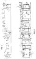
- the business forms press of this embodiment of the invention generally includes an infeed supply station 10 for a web W, one or more printing stations 12, a line hole punch ring station 14, an image scanning station 16, a laser slitter station 18, a laser punch station 20, a laser cross perforation station 22, additional detectors 24 and a rewind station 26.
- the infeed station 10 includes a conventional paper supply roll 30, provided with web guides 32 and feed rollers 34.
- at least one laser detector 36 may be provided for monitoring web thickness. While large variations in thickness are not normally found within a single paper roll, the second or third roll used in a process may, in fact, contain thickness variations large enough to create stretch problems in the web.
- the laser detector serves to alert the press operator of variations beyond a predetermined acceptable minimum so that the problem may be corrected. Detectors using laser radiation for measuring web thickness are not new per se. See, for example, U.S. Patent No. 4,322,971 for a representative example of the type of detector which can be utilized in this invention.
- a pair of compensator rolls 38 are employed in order to indicate slack and uneven feed of paper from the supply roll 30. These rolls are operatively connected with the central computer control unit 52 which adjusts the infeed rolls 34 as required.
- the printing station 12 includes a unique, indeterminate length printing cylinder 40 which, as earlier stated, enables printing to any desired length or repeat.
- each printing cylinder 40 (there may be as many as four or more arranged in series) is preferably constructed of aluminum and coated with a suitable photoconductive surface for receiving an image from an image projector 42.
- the projector 42 utilizes lasers to project an image onto the photosensitive recording medium applied on the drum surface.
- the drum or cylinder at each printing station should be mounted for easy installation and removal so that the cylinder may be removed periodically for recoating.
- the printing stations will receive, for example, alpha and numeric character data in electronic form from the main computer control unit 52, as will be described further hereinbelow, and, in response to such data, print the desired characters on the moving web W.
- Each printing station 12 may have its own light motor drive M and its own computer (not shown). This computer could have its own program to control spacing and tension of the web in that particular station, but would of course, interface with the main computer control 52.
- a toner in the form of powder is applied at 44.
- the powder should be extremely fine grained so that when it is picked up by the surface, there is no waste or extraneous material thereon.
- the powder is fused and chilled at 48, 50, respectively (see FIGURE 4). Fusing temperatures should be greater than 150°C (300°F).
- the image is erased by an ionized image eraser 46.
- lasers are utilized or discharge the photoconductive surface of the printing drums or cylinders.
- the individual drums would be scanned to a required length, e.g., 61 cm (24 ⁇ ) on a 71 cm (28 ⁇ ) drum, and as the cylinder revolves past the printing point and the image is erased, a new or continuing image is projected on the cylinder. In this way, no open non-printing are created.
- the size of the cylinder is not restricted to 71 cm (28 ⁇ ), but may be 56 cm (22 ⁇ ) or 66 cm (26 ⁇ ) or whatever size is most practical for the job at hand.
- the effective infinite length of the cylinder it is possible to print four (or more) 28 cm (11 ⁇ ) images and create a four-part form on a single sheet length of the continuous web. Conventional printing presses, and even those with newer laser printers are unable to create such four-part forms.
- the laser drum printing station 12 described above is one of as many as four such stations, arranged in series along the path of travel of the web W, each one applying a different one of four primary colors. Obviously, the type and style of form will dictate the number of colors, and hence the number of stations required.
- the press may be programmed to have the printing stations print in any given sequence, by color, so that, for example, the first station would print black; the second, red; the third, blue; and the fourth, green.
- the web W After exiting the printing stations, the web W passes through a conventional line hole punch ring station 14 and below an image scanner 16, and thereafter through a laser slitter 18, laser punch head 20 and laser cross perforation cutter 22.
- the size, location, spacing, and so on of the various holes and slits is governed by the use of pre-programmed information on diskettes or cassettes, insertable in the main control unit as described further herein.
- the image scanner 16 reproduces the printed image and resolves the four color image in a lathe type mechanism, picks out the colors and separates them by digitizing, and produces four separate negatives, one for each color. Rather than producing a negative, this information could be conveyed directly to the printing stations of the press, particularly to correct and/or improve the work product, or transmitted by computer link to a remote press or presses.
- the paper After passing between detectors 24, which insure proper alignment and tautness of the paper web W, the paper is rewound at a stand 26.
- FIGURE 3 there is illustrated a schematic diagram of the various components utilized to control the press of this invention.
- a forms composer with full color graphics, shown at 60, and a matrix color printer 62 for forms proofs are utilized in conjunction with a processor 64 and color scanner 66 to provide the central processor 52 with the necessary information regarding the four color composition of the forms.
- a console 68 is provided for inserting the various cassettes or diskettes for controlling each of the stations of the press, through the main computer control 52.
- the diskette When the job is finished, the diskette is stored for a repeat order, and is ready to set the press for an exact repeat, or the diskette can be altered with new or deleted copy, without the necessity for resetting the total job, or reworking the press memory diskette section when needed.
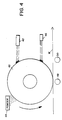
- FIGURE 4 there is shown a close-up schematic of a laser printing station similar to that illustrated in FIGURE 1 but wherein the web W passes below a drum 40.
- the image is projected onto the photosensitive surface of the drum at 42 and powder is applied at 44.
- the powder is fused at 48 and chilled at 50, while immediately thereafter, the image on the drum is erased at 46.
- the present invention has been described particularly in the context of printing business forms per se. It is contemplated that the computerized process of this invention may further be utilized to produce bar coding on the forms in a simple and efficient manner. It will be further appreciated that the indeterminate length cylinder as disclosed herein may also be advantageously employed in the production of other web-oriented processes, for example, in the publishing field, and in the printing of wallpaper. In the production of the latter, a customized product could be produced with a continuously varying pattern, i.e., at no point in a room need there be a pattern repeat.
Landscapes
- Physics & Mathematics (AREA)
- General Physics & Mathematics (AREA)
- Optics & Photonics (AREA)
- Accessory Devices And Overall Control Thereof (AREA)
- Handling Of Sheets (AREA)
- Manufacture Or Reproduction Of Printing Formes (AREA)
Claims (22)
- Verfahren zum Bedrucken einer Papierbahn (W) eines kontinuierlichen Druckmaterials in einer Druckpresse mit folgenden Verfahrensschritten:(a) Zuführen einer Papierbahn (W) eines kontinuierlichen Druckmaterials von einer Vorratsrolle (30) zu einer Druckstation (12);(b) Projizieren eines sich ändernden Bildes auf eine Druckwalze (40) und Entwickeln des Bildes;(c) Übertragen des entwickelten Bildes auf die Papierbahn in der Druckstation (12), während die Papierbahn (W) und die Druckwalze (40) sich aneinander vorbei bewegen, wobei die Länge des auf die Papierbahn aufgetragenen Bildes unabhängig von dem Durchmesser der Druckwalze ist;(d) Löschen des Bildes von der Druckwalze (40) unmittelbar nach dem Verfahrensschritt (c);
gekennzeichnet durch den weiteren Verfahrensschritt(e) Abtasten des auf die Papierbahn (W) übertragenen Bildes, um Abweichungen von einer vorbestimmten Bildgestaltung zu erfassen und um derartige Abweichungen zu kompensieren. - Verfahren nach Anspruch 1, wobei die Verfahrensschritte (a) bis (d) zum Drucken bei einer Mehrzahl von Druckstationen durchgeführt werden, wobei bei jeder Druckstation der Druckvorgang in einer unterschiedlichen Farbe erfolgt.
- Verfahren nach Anspruch 2, wobei das Drucken in einer Mehrzahl von Druckstationen erfolgt, welche in Reihe angeordnet sind.
- Verfahren nach Anspruch 2 oder 3, wobei der Druckvorgang in einer der Druckstationen in schwarz erfolgt und in einer weiteren Druckstation in einer primären Farbe erfolgt, welche aus den Farben rot, grün oder blau ausgewählt ist.
- Verfahren nach einem der vorangehenden Ansprüche, wobei Schritt (b) durch Projektion ausgehend von einer Lichtquelle (42) durchgeführt wird.
- Verfahren nach Anspruch 5, wobei der Schritt (b) durch Projektion ausgehend von mindestens einem Laser durchgeführt wird.
- Verfahren nach Anspruch 6, wobei der Verfahrensschritt (b) durch Projektion ausgehend von einer Mehrzahl von Lasern durchgeführt wird.
- Verfahren nach einem der vorangehenden Ansprüche, wobei der Verfahrensschritt (b) das Projizieren eines Ladungsbildes auf eine fotoemfindlichen Oberfläche der Druckwalze enthält, und wobei das Verfahren weiter den Verfahrensschritt des Aufbringens von Toner auf das auf der fotoempfindlichen Oberfläche der Druckwalze (40) Ladungsbild enthält, und wobei bei dem Übertragungsschritt Toner auf die Papierbahn (W) des kontinuierlichen Druckmaterials entsprechend des Ladungsbildes aufgebracht wird.
- Verfahren nach Anspruch 8, wobei weiter der Verfahrensschritt des Fixierens des Tonerbildes auf der Papierbahn (W) des kontinuierlichen Druckmaterials erfolgt.
- Verfahren nach einem der vorangehenden Ansprüche, wobei weiter der Schritt des Überwachens der Dicke der Papierbahn vor der Durchführung des Verfahrensschritts (b) vorgesehen ist.
- Verfahren nach einem der vorangehenden Ansprüche, wobei weiter der Verfahrensschritt des Schneidens der Papierbahn an vorbestimmten Stellen vorgesehen ist.
- Verfahren nach einem der vorangehenden Ansprüche, wobei weiter der Verfahrensschritt des Perforierens der Papierbahn an vorbestimmten Stellen vorgesehen ist.
- Verfahren nach einem der vorangehenden Ansprüche, wobei die Verfahrensschritte (a) bis (e) von einem Computerprogramm geregelt durchgeführt werden.
- Verfahren nach einem der vorangehenden Ansprüche, wobei sich ständig ändernde, alphanumerische Zeichen-Daten gedruckt werden, um eine gewerbliches Druckerzeugnis herzustellen, wobei die Menge der alphanumerischen Daten unabhängig von dem Baumaß der Druckwalze ist.
- Druckpresse zum Drucken eines sich ändernden Bildes auf eine Papierbahn (W) eines kontinuierlichen Druckmaterials, gekennzeichnet durch:(a) Vorschubeinrichtungen (34, 38) zum Zuführen der Papierbahn (W) aus kontinuierlichem Druckmaterial von einer Vorratsrolle (30) zu einer Druckstation (12);(b) eine Druckwalze (40) zum Aufnehmen des zu druckenden Bildes;(c) Antriebseinrichtungen zum Antreiben der Druckwalze der Druckstation (12);(d) Projektionseinrichtungen zum Projizieren des Bildes auf die Druckwalze (40) und Entwicklungseinrichtungen (44) zum Entwickeln des Bildes, wobei die Länge des auf die Papierbahn aufgetragenen Bildes unabhängig von dem Durchmesser der Druckwalze ist;(e) Übertragungseinrichtungen zum Übertragen des entwickelten Bildes von der Druckwalze (40) auf die Papierbahn (W) in der Druckstation (12), während die Papierbahn (W) und die Druckwalze (40) sich aneinander vorbeibewegen; und(f) Löscheinrichtungen (46) zum Löschen des Bildes von der Druckwalze (40) unmittelbar hinter der Druckstation, dadurch gekennzeichnet, daß die Druckpresse weiter eine Abtasteinrichtung (16) zu Abtasten des auf die Papierbahn (W) übertragenen Bildes zum Erfassen von Abweichungen von einem vorbestimmten Design des Bildes aufweist, welches auf die Druckwalze (40) zu projizieren ist, und Einrichtungen aufweist, welche mit der Abtasteinrichtung (16) gekoppelt sind, um die Abweichungen zu kompensieren.
- Druckpresse nach Anspruch 15, wobei die Druckwalze (40) dazu geeignet ist, in periodischen Zeitabständen entfernt zu werden.
- Druckpresse nach Anspruch 15 oder Anspruch 16, wobei weiter ein Computer zum Regeln der Druckpresse vorgesehen ist.
- Druckpresse nach einem der Ansprüche 15 bis 17 und eine Mehrzahl von Druckstationen aufweist, welche für das Bedrucken mit einer Mehrzahl von Farben geeignet sind.
- Druckpresse nach einem der Ansprüche 15 bis 18 und weiter Einrichtungen (24) zum Schneiden der Papierbahn (W) des kontinuierlichen Druckmaterials aufweist.
- Druckpresse nach einem der Ansprüche 15 bis 19, welche weiter Einrichtungen (14) zum Perforieren der Papierbahn (W) aus kontinuierlichem Druckmaterial an vorbestimmten Stellen aufweist.
- Druckpresse nach einem der Ansprüche 15 bis 20, wobei die Projektionseinrichtungen (42) die Oberfläche der Druckwalze (40) mit einem Ladungsbild beschicken, welches dem zu druckenden Bild entspricht, und wobei die Entwicklungseinrichtungen (44) Auftrageinrichtungen zum Auftragen von Toner auf das Ladungsbild auf der Oberfläche aufweisen, und die Übertragungseinrichtungen den Toner auf die Papierbahn (W) zum Drucken übertragen, wobei die Druckwalze (40) und die Papierbahn (W) sich aneinander vorbeibewegen,
wobei die Druckpresse weiter Fixiereinrichtungen (48, 50) zum Fixieren des Toners auf der Papierbahn (W) aufweist. - Druckpresse nach Anspruch 21, wobei die Löscheinrichtungen (46) eine Entladungseinrichtung zum Entladen des Ladungsbildes auf der Oberfläche der Druckwalze (40) aufweisen.
Priority Applications (2)
| Application Number | Priority Date | Filing Date | Title |
|---|---|---|---|
| DE1989621066 DE68921066T2 (de) | 1989-04-28 | 1989-04-28 | Druckerpresse. |
| EP94201206A EP0611019A3 (de) | 1986-12-16 | 1989-04-28 | Druckpresse. |
Applications Claiming Priority (1)
| Application Number | Priority Date | Filing Date | Title |
|---|---|---|---|
| US06/942,324 US4827315A (en) | 1986-12-16 | 1986-12-16 | Printing press |
Related Child Applications (1)
| Application Number | Title | Priority Date | Filing Date |
|---|---|---|---|
| EP94201206.3 Division-Into | 1994-05-02 |
Publications (2)
| Publication Number | Publication Date |
|---|---|
| EP0394576A1 EP0394576A1 (de) | 1990-10-31 |
| EP0394576B1 true EP0394576B1 (de) | 1995-02-08 |
Family
ID=25477922
Family Applications (2)
| Application Number | Title | Priority Date | Filing Date |
|---|---|---|---|
| EP94201206A Withdrawn EP0611019A3 (de) | 1986-12-16 | 1989-04-28 | Druckpresse. |
| EP89304337A Revoked EP0394576B1 (de) | 1986-12-16 | 1989-04-28 | Druckerpresse |
Family Applications Before (1)
| Application Number | Title | Priority Date | Filing Date |
|---|---|---|---|
| EP94201206A Withdrawn EP0611019A3 (de) | 1986-12-16 | 1989-04-28 | Druckpresse. |
Country Status (3)
| Country | Link |
|---|---|
| US (1) | US4827315A (de) |
| EP (2) | EP0611019A3 (de) |
| AU (1) | AU616513B2 (de) |
Cited By (1)
| Publication number | Priority date | Publication date | Assignee | Title |
|---|---|---|---|---|
| DE4417177A1 (de) * | 1994-05-17 | 1995-11-23 | Heidelberger Druckmasch Ag | Druckzylinder einer Druckmaschine sowie Verfahren zum mit einem Druckzylinder erfolgenden Drucken |
Families Citing this family (33)
| Publication number | Priority date | Publication date | Assignee | Title |
|---|---|---|---|---|
| US4827315A (en) * | 1986-12-16 | 1989-05-02 | Larry Wolfberg | Printing press |
| US5178063A (en) | 1986-12-16 | 1993-01-12 | L & C Family Partnership | Method and apparatus for automatic numbering of forms on a rotary printing press |
| US4968993A (en) * | 1986-12-16 | 1990-11-06 | L&C Family Partnership | Printing press |
| US5001500A (en) * | 1986-12-16 | 1991-03-19 | L & C Family Partnership | Endless belt printing apparatus |
| USRE34406E (en) * | 1987-05-19 | 1993-10-12 | Asahi Kogaku Kogyo Kabushiki Kaisha | Printer for continuous form with justification control |
| US5003352A (en) * | 1989-10-24 | 1991-03-26 | Am International, Inc. | Liquid toner supply system and method |
| US4952301A (en) * | 1989-11-06 | 1990-08-28 | Betz Laboratories, Inc. | Method of inhibiting fouling in caustic scrubber systems |
| US5017964A (en) * | 1989-11-29 | 1991-05-21 | Am International, Inc. | Corona charge system and apparatus for electrophotographic printing press |
| US5077172A (en) * | 1989-12-28 | 1991-12-31 | Am International, Inc. | Carrier web transfer device and method for electrophotographic printing press |
| US5019868A (en) * | 1989-12-28 | 1991-05-28 | Am International, Inc. | Developer electrode and reverse roller assembly for high speed electrophotographic printing device |
| US5177877A (en) * | 1989-12-28 | 1993-01-12 | Am International, Inc. | Dryer-fuser apparatus and method for high speed electrophotographic printing device |
| US5136316A (en) * | 1989-12-29 | 1992-08-04 | Am International Incorporated | Printing press and method |
| US5043749A (en) * | 1989-12-29 | 1991-08-27 | Am International Inc. | Printing press and method |
| US5187501A (en) * | 1990-04-17 | 1993-02-16 | Armstrong World Industries, Inc. | Printing system |
| AU646443B2 (en) * | 1990-04-17 | 1994-02-24 | Armstrong World Industries, Inc. | Non-impact printer |
| US5124730A (en) * | 1990-04-17 | 1992-06-23 | Armstrong World Industries, Inc. | Printing system |
| JPH04174465A (ja) * | 1990-07-25 | 1992-06-22 | Hitachi Ltd | カラー画像電子写真装置 |
| DE59505593D1 (de) * | 1994-01-24 | 1999-05-12 | Oce Printing Systems Gmbh | Dokumentendruckvorrichtung |
| US5787807A (en) * | 1994-05-17 | 1998-08-04 | Heidelberger Druckmaschinen Ag | Sheet-fed rotary printing press with digital imaging |
| US5464289A (en) * | 1994-08-24 | 1995-11-07 | Beaudry; Wallace J. | Electrographic label printing system |
| DE4431669B4 (de) * | 1994-09-06 | 2006-01-12 | Heidelberger Druckmaschinen Ag | Vorrichtung zum Ablegen von mit einer Druckmaschine im fortlaufenden Betrieb erstellten, unterschiedlichen Produkten |
| DE4442411B4 (de) * | 1994-11-29 | 2007-05-03 | Heidelberger Druckmaschinen Ag | Verfahren zur formenden Bearbeitung von Papier in einer Druckmaschine |
| US6332149B1 (en) | 1995-06-07 | 2001-12-18 | R. R. Donnelley & Sons | Imposition process and apparatus for variable imaging system |
| US6327599B1 (en) * | 1995-06-07 | 2001-12-04 | R. R. Donnelley & Sons Company | Apparatus for controlling an electronic press to print fixed and variable information |
| US6952801B2 (en) | 1995-06-07 | 2005-10-04 | R.R. Donnelley | Book assembly process and apparatus for variable imaging system |
| US6246993B1 (en) | 1997-10-29 | 2001-06-12 | R. R. Donnelly & Sons Company | Reorder system for use with an electronic printing press |
| US6205452B1 (en) | 1997-10-29 | 2001-03-20 | R. R. Donnelley & Sons Company | Method of reproducing variable graphics in a variable imaging system |
| US6088710A (en) * | 1997-10-29 | 2000-07-11 | R.R. Donnelley & Sons Company | Apparatus and method for producing fulfillment pieces on demand in a variable imaging system |
| US7278094B1 (en) | 2000-05-03 | 2007-10-02 | R. R. Donnelley & Sons Co. | Variable text processing for an electronic press |
| US20050157132A1 (en) * | 2004-01-21 | 2005-07-21 | Kia Silverbrook | Patterned media produced by a printing system |
| US20070235923A1 (en) * | 2006-04-05 | 2007-10-11 | Keller James J | Sheet feeder, feed roller system and method |
| DE102008021447A1 (de) * | 2008-04-29 | 2009-11-05 | Manroland Ag | Verfahren zum Betreiben einer in eine Rollendruckmaschine integrierten Bearbeitungseinrichtung |
| JP7005912B2 (ja) * | 2017-03-02 | 2022-01-24 | 富士フイルムビジネスイノベーション株式会社 | 画像形成装置 |
Citations (2)
| Publication number | Priority date | Publication date | Assignee | Title |
|---|---|---|---|---|
| US4729310A (en) * | 1982-08-09 | 1988-03-08 | Milliken Research Corporation | Printing method |
| US4792860A (en) * | 1987-02-27 | 1988-12-20 | Kuehrle Manfred R | Thermodynamic printing method and means |
Family Cites Families (27)
| Publication number | Priority date | Publication date | Assignee | Title |
|---|---|---|---|---|
| US2539068A (en) * | 1946-08-12 | 1951-01-23 | Nelson E Funk | Cylinder adjusting mechanism for multicolor printing presses |
| US3147006A (en) * | 1963-07-09 | 1964-09-01 | James B Fulk | Method and apparatus for printing and/or processing webs of material |
| US3410203A (en) * | 1967-02-01 | 1968-11-12 | Rca Corp | Non-impact printer employing laser beam and holographic images |
| US3576367A (en) * | 1968-09-06 | 1971-04-27 | Ibm | Machine for preparing documents |
| US3654864A (en) * | 1970-01-16 | 1972-04-11 | Energy Conversion Devices Inc | Printing employing materials with variable volume |
| US3701996A (en) * | 1970-12-02 | 1972-10-31 | United Aircraft Corp | Transfer electrostatic printing system |
| US3858777A (en) * | 1972-05-17 | 1975-01-07 | Xerox Corp | Printing apparatus including registration control |
| US3836917A (en) * | 1973-04-16 | 1974-09-17 | J Mee | High-speed non-impact laser printing apparatus |
| US3911818A (en) * | 1973-09-04 | 1975-10-14 | Moore Business Forms Inc | Computer controlled ink jet printing |
| JPS5753595B2 (de) * | 1973-09-07 | 1982-11-13 | ||
| US3965476A (en) * | 1974-07-05 | 1976-06-22 | Per E. Wenander | Laser printing method and system |
| US4031818A (en) * | 1974-10-16 | 1977-06-28 | Gaf Corporation | Apparatus for preparing sealed envelope units with messages |
| US4046471A (en) * | 1975-11-03 | 1977-09-06 | International Business Machines Corporation | Dual mode electrophotographic apparatus having dual function printing beam |
| JPS5317340A (en) * | 1976-07-30 | 1978-02-17 | Canon Inc | Recording device |
| DE2913879C2 (de) * | 1979-04-06 | 1982-10-28 | Frieseke & Hoepfner Gmbh, 8520 Erlangen | Verfahren zur Regelung der Dicke von laufenden Meßgutbahnen |
| US4348100A (en) * | 1980-09-02 | 1982-09-07 | Xerox Corporation | Control for xerographic system |
| JPS58117566A (ja) * | 1982-01-06 | 1983-07-13 | Ricoh Co Ltd | 給紙装置 |
| JPS58133081A (ja) * | 1982-02-02 | 1983-08-08 | Canon Inc | 画像記録装置 |
| JPS58163962A (ja) * | 1982-03-25 | 1983-09-28 | Fujitsu Ltd | プリンタ装置 |
| JPS5995569A (ja) * | 1982-11-25 | 1984-06-01 | Fuji Xerox Co Ltd | 複写機等の定着兼ミシン目加工装置 |
| DE3406244A1 (de) | 1984-02-21 | 1985-08-22 | Siemens AG, 1000 Berlin und 8000 München | Laserdrucksystem fuer mehrfarben- und rueckseitendruck |
| US4627707A (en) * | 1984-06-16 | 1986-12-09 | Ricoh Company, Ltd. | Copier with image editing function |
| US4559855A (en) * | 1984-07-23 | 1985-12-24 | Xerox Corporation | Plural mode copy sheet output slitter |
| US4611908A (en) * | 1984-12-24 | 1986-09-16 | Eastman Kodak Company | Apparatus and method for forming reproductions with desired margin areas |
| US4809027A (en) * | 1986-07-29 | 1989-02-28 | Markem Corporation | Offset electrostatic printing utilizing a heated air flow |
| US4827315A (en) * | 1986-12-16 | 1989-05-02 | Larry Wolfberg | Printing press |
| JPS63120261U (de) * | 1987-01-30 | 1988-08-03 |
-
1986
- 1986-12-16 US US06/942,324 patent/US4827315A/en not_active Expired - Fee Related
-
1989
- 1989-04-28 EP EP94201206A patent/EP0611019A3/de not_active Withdrawn
- 1989-04-28 EP EP89304337A patent/EP0394576B1/de not_active Revoked
- 1989-05-01 AU AU33883/89A patent/AU616513B2/en not_active Ceased
Patent Citations (2)
| Publication number | Priority date | Publication date | Assignee | Title |
|---|---|---|---|---|
| US4729310A (en) * | 1982-08-09 | 1988-03-08 | Milliken Research Corporation | Printing method |
| US4792860A (en) * | 1987-02-27 | 1988-12-20 | Kuehrle Manfred R | Thermodynamic printing method and means |
Non-Patent Citations (1)
| Title |
|---|
| LASER PRINTING: The fundamentals, by William White, Carnegie Press 1983, Inc, Madison, N.J., pp. 11,17,19,53,54 * |
Cited By (2)
| Publication number | Priority date | Publication date | Assignee | Title |
|---|---|---|---|---|
| DE4417177A1 (de) * | 1994-05-17 | 1995-11-23 | Heidelberger Druckmasch Ag | Druckzylinder einer Druckmaschine sowie Verfahren zum mit einem Druckzylinder erfolgenden Drucken |
| DE4417177C2 (de) * | 1994-05-17 | 2002-03-28 | Anton Rodi | Verfahren zum Bedrucken von Bogen mit Bogendruckmaschinen |
Also Published As
| Publication number | Publication date |
|---|---|
| AU3388389A (en) | 1990-11-29 |
| EP0394576A1 (de) | 1990-10-31 |
| US4827315A (en) | 1989-05-02 |
| EP0611019A2 (de) | 1994-08-17 |
| EP0611019A3 (de) | 1995-05-10 |
| AU616513B2 (en) | 1991-10-31 |
Similar Documents
| Publication | Publication Date | Title |
|---|---|---|
| EP0394576B1 (de) | Druckerpresse | |
| US5001500A (en) | Endless belt printing apparatus | |
| US5043749A (en) | Printing press and method | |
| US6148724A (en) | Selective flexographic printing | |
| US5136316A (en) | Printing press and method | |
| US4968993A (en) | Printing press | |
| EP0672937B1 (de) | Zubringervorrichtung von photographischem Material | |
| US5147745A (en) | Apparatus for producing raised multiple color images | |
| EP0402079B1 (de) | Druckverfahren für Probe- und Flachdruck unter Nutzung eines elektrophotographischen Aufzeichnungsmittels | |
| US3679302A (en) | Method and means for reproducing printed material | |
| US20060098071A1 (en) | Cutting apparatus, cutting method, and printer | |
| JP2005193547A (ja) | プリンタおよびプリントシステム | |
| US7588382B2 (en) | Sheet processing apparatus and image forming apparatus | |
| JP3989580B2 (ja) | 写真プリント作成方法および装置 | |
| CA1298732C (en) | Printing press | |
| US5405723A (en) | Xerographic press capable of simultaneous master making and printing | |
| JPH02303857A (ja) | 印刷方法並びに印刷機 | |
| US20010019402A1 (en) | Image recording apparatus | |
| DE68921066T2 (de) | Druckerpresse. | |
| JPH10308856A (ja) | 画像情報記録方法およびその装置 | |
| JP3668600B2 (ja) | 画像出力装置 | |
| JPH1058652A (ja) | 印刷装置および印刷方法 | |
| JPH1049050A (ja) | シール製造装置 | |
| JP2007105933A (ja) | 画像記録装置及び画像記録方法 | |
| JP2005001224A (ja) | 画像記録装置および画像記録システム |
Legal Events
| Date | Code | Title | Description |
|---|---|---|---|
| PUAI | Public reference made under article 153(3) epc to a published international application that has entered the european phase |
Free format text: ORIGINAL CODE: 0009012 |
|
| AK | Designated contracting states |
Kind code of ref document: A1 Designated state(s): DE FR GB IT SE |
|
| 17P | Request for examination filed |
Effective date: 19910422 |
|
| 17Q | First examination report despatched |
Effective date: 19920714 |
|
| GRAA | (expected) grant |
Free format text: ORIGINAL CODE: 0009210 |
|
| RAP1 | Party data changed (applicant data changed or rights of an application transferred) |
Owner name: ADVANCED LICENSING LIMITED PARTNERSHIP |
|
| AK | Designated contracting states |
Kind code of ref document: B1 Designated state(s): DE FR GB IT SE |
|
| ITF | It: translation for a ep patent filed | ||
| ET | Fr: translation filed | ||
| REF | Corresponds to: |
Ref document number: 68921066 Country of ref document: DE Date of ref document: 19950323 |
|
| PLBI | Opposition filed |
Free format text: ORIGINAL CODE: 0009260 |
|
| 26 | Opposition filed |
Opponent name: XEIKON NV Effective date: 19951102 |
|
| PLAB | Opposition data, opponent's data or that of the opponent's representative modified |
Free format text: ORIGINAL CODE: 0009299OPPO |
|
| PLBQ | Unpublished change to opponent data |
Free format text: ORIGINAL CODE: EPIDOS OPPO |
|
| PLBF | Reply of patent proprietor to notice(s) of opposition |
Free format text: ORIGINAL CODE: EPIDOS OBSO |
|
| R26 | Opposition filed (corrected) |
Opponent name: XEIKON NV Effective date: 19951102 |
|
| PLBF | Reply of patent proprietor to notice(s) of opposition |
Free format text: ORIGINAL CODE: EPIDOS OBSO |
|
| PLBF | Reply of patent proprietor to notice(s) of opposition |
Free format text: ORIGINAL CODE: EPIDOS OBSO |
|
| PLBF | Reply of patent proprietor to notice(s) of opposition |
Free format text: ORIGINAL CODE: EPIDOS OBSO |
|
| PGFP | Annual fee paid to national office [announced via postgrant information from national office to epo] |
Ref country code: GB Payment date: 19961028 Year of fee payment: 8 |
|
| PGFP | Annual fee paid to national office [announced via postgrant information from national office to epo] |
Ref country code: SE Payment date: 19961030 Year of fee payment: 8 Ref country code: FR Payment date: 19961030 Year of fee payment: 8 |
|
| PLBF | Reply of patent proprietor to notice(s) of opposition |
Free format text: ORIGINAL CODE: EPIDOS OBSO |
|
| PGFP | Annual fee paid to national office [announced via postgrant information from national office to epo] |
Ref country code: DE Payment date: 19961227 Year of fee payment: 8 |
|
| PLBF | Reply of patent proprietor to notice(s) of opposition |
Free format text: ORIGINAL CODE: EPIDOS OBSO |
|
| PLBF | Reply of patent proprietor to notice(s) of opposition |
Free format text: ORIGINAL CODE: EPIDOS OBSO |
|
| PG25 | Lapsed in a contracting state [announced via postgrant information from national office to epo] |
Ref country code: GB Effective date: 19970428 |
|
| PG25 | Lapsed in a contracting state [announced via postgrant information from national office to epo] |
Ref country code: SE Effective date: 19970429 |
|
| GBPC | Gb: european patent ceased through non-payment of renewal fee |
Effective date: 19970428 |
|
| PG25 | Lapsed in a contracting state [announced via postgrant information from national office to epo] |
Ref country code: FR Free format text: LAPSE BECAUSE OF NON-PAYMENT OF DUE FEES Effective date: 19971231 |
|
| PG25 | Lapsed in a contracting state [announced via postgrant information from national office to epo] |
Ref country code: DE Free format text: LAPSE BECAUSE OF NON-PAYMENT OF DUE FEES Effective date: 19980101 |
|
| EUG | Se: european patent has lapsed |
Ref document number: 89304337.2 |
|
| PLAW | Interlocutory decision in opposition |
Free format text: ORIGINAL CODE: EPIDOS IDOP |
|
| REG | Reference to a national code |
Ref country code: FR Ref legal event code: ST |
|
| PLAW | Interlocutory decision in opposition |
Free format text: ORIGINAL CODE: EPIDOS IDOP |
|
| RDAH | Patent revoked |
Free format text: ORIGINAL CODE: EPIDOS REVO |
|
| RDAG | Patent revoked |
Free format text: ORIGINAL CODE: 0009271 |
|
| STAA | Information on the status of an ep patent application or granted ep patent |
Free format text: STATUS: PATENT REVOKED |
|
| 27W | Patent revoked |
Effective date: 19990221 |