EP0394672A2 - Procédé et appareil à couper les spires en tête et/ou les spires traînantes d'une bobine de fil - Google Patents
Procédé et appareil à couper les spires en tête et/ou les spires traînantes d'une bobine de fil Download PDFInfo
- Publication number
- EP0394672A2 EP0394672A2 EP90105413A EP90105413A EP0394672A2 EP 0394672 A2 EP0394672 A2 EP 0394672A2 EP 90105413 A EP90105413 A EP 90105413A EP 90105413 A EP90105413 A EP 90105413A EP 0394672 A2 EP0394672 A2 EP 0394672A2
- Authority
- EP
- European Patent Office
- Prior art keywords
- roller table
- turns
- main conveyor
- wire
- speed
- Prior art date
- Legal status (The legal status is an assumption and is not a legal conclusion. Google has not performed a legal analysis and makes no representation as to the accuracy of the status listed.)
- Granted
Links
Images
Classifications
-
- B—PERFORMING OPERATIONS; TRANSPORTING
- B21—MECHANICAL METAL-WORKING WITHOUT ESSENTIALLY REMOVING MATERIAL; PUNCHING METAL
- B21C—MANUFACTURE OF METAL SHEETS, WIRE, RODS, TUBES, PROFILES OR LIKE SEMI-MANUFACTURED PRODUCTS OTHERWISE THAN BY ROLLING; AUXILIARY OPERATIONS USED IN CONNECTION WITH METAL-WORKING WITHOUT ESSENTIALLY REMOVING MATERIAL
- B21C47/00—Winding-up, coiling or winding-off metal wire, metal band or other flexible metal material characterised by features relevant to metal processing only
- B21C47/26—Special arrangements with regard to simultaneous or subsequent treatment of the material
- B21C47/262—Treatment of a wire, while in the form of overlapping non-concentric rings
-
- Y—GENERAL TAGGING OF NEW TECHNOLOGICAL DEVELOPMENTS; GENERAL TAGGING OF CROSS-SECTIONAL TECHNOLOGIES SPANNING OVER SEVERAL SECTIONS OF THE IPC; TECHNICAL SUBJECTS COVERED BY FORMER USPC CROSS-REFERENCE ART COLLECTIONS [XRACs] AND DIGESTS
- Y10—TECHNICAL SUBJECTS COVERED BY FORMER USPC
- Y10S—TECHNICAL SUBJECTS COVERED BY FORMER USPC CROSS-REFERENCE ART COLLECTIONS [XRACs] AND DIGESTS
- Y10S83/00—Cutting
- Y10S83/907—Coiled wire cutting
-
- Y—GENERAL TAGGING OF NEW TECHNOLOGICAL DEVELOPMENTS; GENERAL TAGGING OF CROSS-SECTIONAL TECHNOLOGIES SPANNING OVER SEVERAL SECTIONS OF THE IPC; TECHNICAL SUBJECTS COVERED BY FORMER USPC CROSS-REFERENCE ART COLLECTIONS [XRACs] AND DIGESTS
- Y10—TECHNICAL SUBJECTS COVERED BY FORMER USPC
- Y10T—TECHNICAL SUBJECTS COVERED BY FORMER US CLASSIFICATION
- Y10T83/00—Cutting
- Y10T83/04—Processes
- Y10T83/0405—With preparatory or simultaneous ancillary treatment of work
- Y10T83/0419—By distorting within elastic limit
- Y10T83/0424—By stretching
-
- Y—GENERAL TAGGING OF NEW TECHNOLOGICAL DEVELOPMENTS; GENERAL TAGGING OF CROSS-SECTIONAL TECHNOLOGIES SPANNING OVER SEVERAL SECTIONS OF THE IPC; TECHNICAL SUBJECTS COVERED BY FORMER USPC CROSS-REFERENCE ART COLLECTIONS [XRACs] AND DIGESTS
- Y10—TECHNICAL SUBJECTS COVERED BY FORMER USPC
- Y10T—TECHNICAL SUBJECTS COVERED BY FORMER US CLASSIFICATION
- Y10T83/00—Cutting
- Y10T83/323—With means to stretch work temporarily
Definitions
- the invention specifically relates to a method for coupling the initial windings and / or windings of a wire bundle in the course of fanning out wire rod to be bundled behind the finished block of a wire rolling mill to which a winding layer for the wire, a roller table, a main conveyor and a collecting mandrel are connected, wherein the winding layer works on the roller table and the roller table on the main conveyor running at a predetermined main conveying speed and the collecting mandrel receives at least one wire bundle, the wire being fanned out in turns on the roller table and the turns being transferred to the main conveyor, on which the treatment is fanned out Winding of the wire takes place, the initial turns and / or end turns also being coupled on the main conveyor.
- a water cooling section can be arranged between the prefabricated block and the winding layer.
- the cooling on the main conveyor is generally, but not necessarily, controlled cooling with metallurgical purposes. Coupling is carried out with suitable auxiliary devices, but is still carried out by hand today.
- the wire In a bundle of wires that is brought to the market, the wire must start from the beginning meet quality requirements and tolerances to the end. Couping must be carried out accordingly accurately and in spite of the high rolling speed of modern wire rolling mills. It goes without saying that the required measurements are connected upstream of the coupé and that the measurement results are taken into account during the coupé.
- roller table of about 1 to 2 m in length is arranged directly behind the winding layer. Behind the roller table follows the main conveyor in the direction of transport of the wire, the z. B. is designed as a chain conveyor. The purpose of this roller table upstream of the main conveyor is to prevent the wire tip emerging from the winding layer from getting caught at the beginning of a rolling process.
- the roller table is designed accordingly.
- the invention has for its object to carry out the method described above so that the coupling of the initial turns and / or end turns and the removal of the cut initial turns or end turns can be done without difficulty.
- the invention is further based on the object of specifying a system with which the method according to the invention can be carried out in a particularly simple manner.
- the invention teaches that the roller table is operated at a roller table speed which is greater than the main conveyor speed when the initial turns and / or end turns of a wire bundle to be formed emerge from the winding layer, the wire windings being deposited on the roller table with a coupling fan , which is larger than the treatment fan, that the roller table is switched to the main conveyor speed as soon as or before the first of the windings designed with a coupier fan reaches the main conveyor and the windings designed with a coupier fan are handed over to the main conveyor, and that the couping is carried out on the main conveyor in the area of the coupier fanning out of the turns, - while the following turns on the roller table are again laid out with treatment fanning out.
- the increased roller table speed for depositing the windings with coupier fan out can be changed depending on the product. It is understood that in the context of the invention, the couping can be carried out by hand. According to a preferred embodiment of the invention, however, the couping takes place automatically with auxiliary devices as described at the beginning.
- the invention also relates to a plant for carrying out the method according to the invention, as characterized in claims 4 and 5.
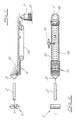
- the system shown in the figures for the implementation of the method according to the invention works behind the finishing block 1 of a wire rolling mill which adjoins on the left.
- it consists of a water cooling section 2, a winding layer 3 for the wire, a roller table 4 on which the fanned-out wire turns 5 can be seen, a main conveyor 6 and a collecting mandrel 7 for receiving the turns 5 from a wire bundle 8 to be formed.
- the arrangement is such that the main conveyor 6 works with a predetermined main conveyor speed that can be set up depending on the product. This has been indicated in FIGS. 1 and 2 by an arrow. It is understood that the main conveyor has a corresponding drive, which has not been marked.
- the upstream roller table 4 has its own drive. It can be driven for the purpose of coupling initial windings and end windings of a wire bundle 8 on the main conveyor 6 at a roller table speed which is greater than the main conveyor speed set up in each case.
- the cutting machine 9 is indicated in FIG. 2. Otherwise, the arrangement is such that this increased roller table speed can be switched to the main conveyor speed.
- a computer which controls the roller table in accordance with the coupling to be carried out in accordance with program and / or measurement data, which has not been drawn.
- the roller table 4 is operated at the exit of the initial turns 5 and / or end turns 5 of a wire bundle 8 to be formed from the winding layer 3 at a roller table speed that is greater than the main conveying speed.
- the roller table 4 is switched over to the main conveying speed as soon as or before the first of the windings designed with a coupe fan has reached the main conveyor, so that the windings 5 designed with a coupe fan are transferred to the main conveyor. They are in the order of manufacture in the winding layer.
- the turns to be cut can be easily and cleanly cut off with the cutting machine 9 without getting caught.
Landscapes
- Engineering & Computer Science (AREA)
- Mechanical Engineering (AREA)
- Winding, Rewinding, Material Storage Devices (AREA)
- Binders And Loading Units For Sheaves (AREA)
- Use Of Switch Circuits For Exchanges And Methods Of Control Of Multiplex Exchanges (AREA)
- Coiling Of Filamentary Materials In General (AREA)
- Wire Processing (AREA)
- Metal Rolling (AREA)
Applications Claiming Priority (4)
| Application Number | Priority Date | Filing Date | Title |
|---|---|---|---|
| DE3913695 | 1989-04-26 | ||
| DE3913695 | 1989-04-26 | ||
| DE3919836 | 1989-06-17 | ||
| DE19893919836 DE3919836A1 (de) | 1989-04-26 | 1989-06-17 | Verfahren und anlage zum coupieren der anfangswindungen und/oder endwindungen eines drahtbundes |
Publications (3)
| Publication Number | Publication Date |
|---|---|
| EP0394672A2 true EP0394672A2 (fr) | 1990-10-31 |
| EP0394672A3 EP0394672A3 (fr) | 1991-07-24 |
| EP0394672B1 EP0394672B1 (fr) | 1994-03-02 |
Family
ID=25880289
Family Applications (1)
| Application Number | Title | Priority Date | Filing Date |
|---|---|---|---|
| EP90105413A Expired - Lifetime EP0394672B1 (fr) | 1989-04-26 | 1990-03-22 | Procédé et appareil à couper les spires en tête et/ou les spires traînantes d'une bobine de fil |
Country Status (7)
| Country | Link |
|---|---|
| US (1) | US4995251A (fr) |
| EP (1) | EP0394672B1 (fr) |
| JP (1) | JPH0366412A (fr) |
| AT (1) | ATE102093T1 (fr) |
| DE (2) | DE3919836A1 (fr) |
| DK (1) | DK0394672T3 (fr) |
| ES (1) | ES2051401T3 (fr) |
Cited By (1)
| Publication number | Priority date | Publication date | Assignee | Title |
|---|---|---|---|---|
| US4790328A (en) * | 1986-09-24 | 1988-12-13 | Young David E | Device for diagnosis and treatment of urinary incontinence |
Families Citing this family (7)
| Publication number | Priority date | Publication date | Assignee | Title |
|---|---|---|---|---|
| DE4329350A1 (de) * | 1993-08-27 | 1995-03-02 | Thaelmann Schwermaschbau Veb | Schopfeinrichtung für Drahtwindungen |
| DE4308777A1 (de) * | 1993-03-19 | 1994-09-22 | Thaelmann Schwermaschbau Veb | Verfahren und Einrichtung zum Schopfen von Drahtwindungen |
| DE19717770A1 (de) * | 1997-04-26 | 1998-10-29 | Schloemann Siemag Ag | Verfahren und Vorrichtung zum Abtrennen und Abtransportieren ungekühlter und nicht toleranzhaltiger Drahtwindungen |
| JP3727553B2 (ja) * | 2001-06-12 | 2005-12-14 | 株式会社クボタ | 作業機の操作構造 |
| ATE417679T1 (de) * | 2005-08-11 | 2009-01-15 | Sms Meer Gmbh | Anlage zum walzen von draht |
| WO2017082908A1 (fr) * | 2015-11-12 | 2017-05-18 | Primetals Technologies Germany Gmbh | Procédé et système de fabrication d'une bobine de fil |
| IT202100030503A1 (it) * | 2021-12-02 | 2023-06-02 | Danieli Off Mecc | Gruppo robotizzato e procedimento per il controllo di un prodotto metallico in movimento in un apparato e procedimento per la produzione di bobine metalliche |
Family Cites Families (13)
| Publication number | Priority date | Publication date | Assignee | Title |
|---|---|---|---|---|
| US3056433A (en) * | 1956-12-15 | 1962-10-02 | Delore Sa Geoffroy | System for handling wire and the like |
| US3103237A (en) * | 1960-08-10 | 1963-09-10 | Crum Eben Jefferson | Wire handling apparatus |
| DE1214635B (de) * | 1964-03-23 | 1966-04-21 | Schloemann Ag | Vorrichtung zum Kuehlen von mittel- und hoch-legiertem Walzdraht |
| US3231432A (en) * | 1964-10-08 | 1966-01-25 | Morgan Construction Co | Process for the quenching of hot rolled rods in direct sequence with rod mill |
| DE1752196A1 (de) * | 1968-04-18 | 1971-05-13 | Schloemann Ag | Verfahren und Vorrichtung zum Unterteilen einer Windungslage |
| GB1246049A (en) * | 1969-05-01 | 1971-09-15 | Templeborough Rolling Mills Lt | Apparatus for shearing rod or wire |
| DE2102684C3 (de) * | 1971-01-21 | 1980-02-28 | Friedrich Kocks Gmbh & Co, 4000 Duesseldorf | Vorrichtung zum Durchtrennen von Walzdraht |
| DE2108907A1 (de) * | 1971-02-25 | 1972-08-31 | Krupp Gmbh | Vorrichtung zum Speichern und Schneiden von Walzdraht |
| GB1510863A (en) * | 1974-05-18 | 1978-05-17 | Bergmann Kabelwerke Ag | Apparatus for feeding lengths of cable coils resting on a distributor conveyor |
| US4088160A (en) * | 1977-05-10 | 1978-05-09 | Bethlehem Steel Corporation | Wire handling apparatus |
| JPS58195202A (ja) * | 1982-05-07 | 1983-11-14 | Nissin Electric Co Ltd | 制御装置におけるレンジ切替装置 |
| US4498505A (en) * | 1983-06-21 | 1985-02-12 | Kamping Jan H | Apparatus for separating a coil from following coils of coiled wire rod |
| JPS6087923A (ja) * | 1983-10-20 | 1985-05-17 | Mitsubishi Heavy Ind Ltd | 線材端末クロツプの排出装置 |
-
1989
- 1989-06-17 DE DE19893919836 patent/DE3919836A1/de not_active Withdrawn
-
1990
- 1990-03-22 EP EP90105413A patent/EP0394672B1/fr not_active Expired - Lifetime
- 1990-03-22 AT AT90105413T patent/ATE102093T1/de not_active IP Right Cessation
- 1990-03-22 DK DK90105413T patent/DK0394672T3/da active
- 1990-03-22 ES ES90105413T patent/ES2051401T3/es not_active Expired - Lifetime
- 1990-03-22 DE DE90105413T patent/DE59004722D1/de not_active Expired - Fee Related
- 1990-04-05 US US07/505,673 patent/US4995251A/en not_active Expired - Fee Related
- 1990-04-20 JP JP2103293A patent/JPH0366412A/ja active Pending
Cited By (1)
| Publication number | Priority date | Publication date | Assignee | Title |
|---|---|---|---|---|
| US4790328A (en) * | 1986-09-24 | 1988-12-13 | Young David E | Device for diagnosis and treatment of urinary incontinence |
Also Published As
| Publication number | Publication date |
|---|---|
| EP0394672A3 (fr) | 1991-07-24 |
| EP0394672B1 (fr) | 1994-03-02 |
| DE3919836A1 (de) | 1990-10-31 |
| DE59004722D1 (de) | 1994-04-07 |
| US4995251A (en) | 1991-02-26 |
| DK0394672T3 (da) | 1994-06-27 |
| JPH0366412A (ja) | 1991-03-22 |
| ES2051401T3 (es) | 1994-06-16 |
| ATE102093T1 (de) | 1994-03-15 |
Similar Documents
| Publication | Publication Date | Title |
|---|---|---|
| DD271254A1 (de) | Vorrichtung zum entholzen von pflanzen mit langen fasern auf dem feld | |
| DE102016216727A1 (de) | Im Endlosbetrieb betreibbare Produktionsanlage und Verfahren zum Betrieb der Produktionsanlage im Störfall | |
| DE2539216A1 (de) | Abbeiz- und walzstrasse | |
| DE2307624A1 (de) | Verfahren und vorrichtung zur kontinuierlichen bearbeitung von bandmaterial | |
| DE2102684A1 (de) | Verfahren zum Durchtrennen von Walzdraht | |
| DE3314319C2 (de) | Vorrichtung zum Spleißen von Bändern | |
| EP0394672B1 (fr) | Procédé et appareil à couper les spires en tête et/ou les spires traînantes d'une bobine de fil | |
| DE69806485T2 (de) | Schleuderstrahlmaschine zur reinigung eines linearmetallelements | |
| DE1452440A1 (de) | Einrichtung zum kontinuierlichen Zufuehren von in Bundform vorliegendem Walzband,in Bearbeitungslinien fuer Baender | |
| DE69012311T2 (de) | Automatisiertes System zum Verpacken und Entfernen von auf Haspeln gewickelten Metalldrahtrollen. | |
| DE3824276C2 (de) | Verfahren zum Trennen von aus einer Walzstraße kontinuierlich herangeförderten, zu Gruppen gesammelten Walzstäben und Trenneinrichtung zur Durchführung des Verfahrens | |
| DE2539697C2 (de) | Gießwalzanlage für Draht | |
| DE4117906C2 (de) | Verfahren und Vorrichtungen zur automatischen Handhabung von Walzdraht in Drahtwalzwerken | |
| DE2917784A1 (de) | Verfahren zum herstellen von flachmaterial aus aluminium, kupfer, stahl oder aus legierungen dieser werkstoffe mittels einer kontinuierlich arbeitenden giessmaschine und vorrichtung zur durchfuehrung des verfahrens | |
| EP0079295A1 (fr) | Procédé et dispositif pour la fabrication de tubes dans un laminoir à froid | |
| DE102015101973B4 (de) | Verfahren und Vorrichtung zur Herstellung von Solarzellsträngen | |
| DE1527867B2 (de) | Wahlweise im edenborn oder garrett system arbeitender haspel fuer walzdraht | |
| DE2702134C2 (de) | Abzieheinrichtung mit nachgeschalteter Haspelvorrichtung für einen Gußstrang in einer horizontalen Stranggießanlage | |
| DE2535480C2 (de) | Verfahren und Vorrichtung zum Aussortieren von Unterlängen und/oder zum Schneiden vorbestimmter Längen aus Stabmaterial unterschiedlicher Längen | |
| DE2246161A1 (de) | Verfahren und anordnung zur steuerung der streifendicke in einem kontinuierlichen tandemwalzwerk | |
| DE4109201A1 (de) | Vorrichtung zum transportieren und schopfen einer walzader | |
| DE3327815C2 (de) | Verfahren und Vorrichtung zur Durchführung des Verfahrens zum Fördern von Längen von Walzdraht | |
| EP1472070B1 (fr) | Procede et un dispositif pour introduire une fibre dans une tete d'injection | |
| DE866351C (de) | Wickelofen in einer Walzenstrasse | |
| DE2826460C3 (de) | Drahtbremsvorrichtung zum Drahtwalzen |
Legal Events
| Date | Code | Title | Description |
|---|---|---|---|
| PUAI | Public reference made under article 153(3) epc to a published international application that has entered the european phase |
Free format text: ORIGINAL CODE: 0009012 |
|
| AK | Designated contracting states |
Kind code of ref document: A2 Designated state(s): AT BE CH DE DK ES FR GB GR IT LI LU NL SE |
|
| PUAL | Search report despatched |
Free format text: ORIGINAL CODE: 0009013 |
|
| AK | Designated contracting states |
Kind code of ref document: A3 Designated state(s): AT BE CH DE DK ES FR GB GR IT LI LU NL SE |
|
| 17P | Request for examination filed |
Effective date: 19911010 |
|
| 17Q | First examination report despatched |
Effective date: 19920612 |
|
| GRAA | (expected) grant |
Free format text: ORIGINAL CODE: 0009210 |
|
| AK | Designated contracting states |
Kind code of ref document: B1 Designated state(s): AT BE CH DE DK ES FR GB GR IT LI LU NL SE |
|
| REF | Corresponds to: |
Ref document number: 102093 Country of ref document: AT Date of ref document: 19940315 Kind code of ref document: T |
|
| EPTA | Lu: last paid annual fee | ||
| REF | Corresponds to: |
Ref document number: 59004722 Country of ref document: DE Date of ref document: 19940407 |
|
| ET | Fr: translation filed | ||
| ITF | It: translation for a ep patent filed | ||
| GBT | Gb: translation of ep patent filed (gb section 77(6)(a)/1977) |
Effective date: 19940415 |
|
| REG | Reference to a national code |
Ref country code: GR Ref legal event code: FG4A Free format text: 3011298 |
|
| REG | Reference to a national code |
Ref country code: ES Ref legal event code: FG2A Ref document number: 2051401 Country of ref document: ES Kind code of ref document: T3 |
|
| REG | Reference to a national code |
Ref country code: DK Ref legal event code: T3 |
|
| PLBE | No opposition filed within time limit |
Free format text: ORIGINAL CODE: 0009261 |
|
| STAA | Information on the status of an ep patent application or granted ep patent |
Free format text: STATUS: NO OPPOSITION FILED WITHIN TIME LIMIT |
|
| EAL | Se: european patent in force in sweden |
Ref document number: 90105413.0 |
|
| 26N | No opposition filed | ||
| PGFP | Annual fee paid to national office [announced via postgrant information from national office to epo] |
Ref country code: GB Payment date: 19970320 Year of fee payment: 8 Ref country code: FR Payment date: 19970320 Year of fee payment: 8 |
|
| PGFP | Annual fee paid to national office [announced via postgrant information from national office to epo] |
Ref country code: NL Payment date: 19970326 Year of fee payment: 8 Ref country code: ES Payment date: 19970326 Year of fee payment: 8 Ref country code: DK Payment date: 19970326 Year of fee payment: 8 |
|
| PGFP | Annual fee paid to national office [announced via postgrant information from national office to epo] |
Ref country code: GR Payment date: 19970327 Year of fee payment: 8 |
|
| PGFP | Annual fee paid to national office [announced via postgrant information from national office to epo] |
Ref country code: AT Payment date: 19970328 Year of fee payment: 8 |
|
| PGFP | Annual fee paid to national office [announced via postgrant information from national office to epo] |
Ref country code: CH Payment date: 19970401 Year of fee payment: 8 |
|
| PGFP | Annual fee paid to national office [announced via postgrant information from national office to epo] |
Ref country code: BE Payment date: 19970403 Year of fee payment: 8 |
|
| PGFP | Annual fee paid to national office [announced via postgrant information from national office to epo] |
Ref country code: LU Payment date: 19970404 Year of fee payment: 8 |
|
| PGFP | Annual fee paid to national office [announced via postgrant information from national office to epo] |
Ref country code: DE Payment date: 19980320 Year of fee payment: 9 |
|
| PG25 | Lapsed in a contracting state [announced via postgrant information from national office to epo] |
Ref country code: LU Free format text: LAPSE BECAUSE OF NON-PAYMENT OF DUE FEES Effective date: 19980322 Ref country code: GB Free format text: LAPSE BECAUSE OF NON-PAYMENT OF DUE FEES Effective date: 19980322 Ref country code: AT Free format text: LAPSE BECAUSE OF NON-PAYMENT OF DUE FEES Effective date: 19980322 |
|
| PG25 | Lapsed in a contracting state [announced via postgrant information from national office to epo] |
Ref country code: ES Free format text: LAPSE BECAUSE OF NON-PAYMENT OF DUE FEES Effective date: 19980323 |
|
| PGFP | Annual fee paid to national office [announced via postgrant information from national office to epo] |
Ref country code: SE Payment date: 19980326 Year of fee payment: 9 |
|
| PG25 | Lapsed in a contracting state [announced via postgrant information from national office to epo] |
Ref country code: LI Free format text: LAPSE BECAUSE OF NON-PAYMENT OF DUE FEES Effective date: 19980331 Ref country code: GR Free format text: LAPSE BECAUSE OF NON-PAYMENT OF DUE FEES Effective date: 19980331 Ref country code: FR Free format text: THE PATENT HAS BEEN ANNULLED BY A DECISION OF A NATIONAL AUTHORITY Effective date: 19980331 Ref country code: DK Free format text: LAPSE BECAUSE OF NON-PAYMENT OF DUE FEES Effective date: 19980331 Ref country code: CH Free format text: LAPSE BECAUSE OF NON-PAYMENT OF DUE FEES Effective date: 19980331 Ref country code: BE Free format text: LAPSE BECAUSE OF NON-PAYMENT OF DUE FEES Effective date: 19980331 |
|
| BERE | Be: lapsed |
Owner name: SCHWERDTFEGER + KUBICEK SYSTEMTECHNIK G.M.B.H. & Effective date: 19980331 Owner name: HAMBURGER STAHLWERKE G.M.B.H. Effective date: 19980331 |
|
| PG25 | Lapsed in a contracting state [announced via postgrant information from national office to epo] |
Ref country code: NL Free format text: LAPSE BECAUSE OF NON-PAYMENT OF DUE FEES Effective date: 19981001 |
|
| GBPC | Gb: european patent ceased through non-payment of renewal fee |
Effective date: 19980322 |
|
| REG | Reference to a national code |
Ref country code: CH Ref legal event code: PL |
|
| NLV4 | Nl: lapsed or anulled due to non-payment of the annual fee |
Effective date: 19981001 |
|
| REG | Reference to a national code |
Ref country code: FR Ref legal event code: ST |
|
| PG25 | Lapsed in a contracting state [announced via postgrant information from national office to epo] |
Ref country code: SE Free format text: LAPSE BECAUSE OF NON-PAYMENT OF DUE FEES Effective date: 19990323 |
|
| EUG | Se: european patent has lapsed |
Ref document number: 90105413.0 |
|
| EUG | Se: european patent has lapsed |
Ref document number: 90105413.0 |
|
| PG25 | Lapsed in a contracting state [announced via postgrant information from national office to epo] |
Ref country code: DE Free format text: LAPSE BECAUSE OF NON-PAYMENT OF DUE FEES Effective date: 20000101 |
|
| REG | Reference to a national code |
Ref country code: DK Ref legal event code: EBP |
|
| REG | Reference to a national code |
Ref country code: ES Ref legal event code: FD2A Effective date: 20000503 |
|
| PG25 | Lapsed in a contracting state [announced via postgrant information from national office to epo] |
Ref country code: IT Free format text: LAPSE BECAUSE OF NON-PAYMENT OF DUE FEES;WARNING: LAPSES OF ITALIAN PATENTS WITH EFFECTIVE DATE BEFORE 2007 MAY HAVE OCCURRED AT ANY TIME BEFORE 2007. THE CORRECT EFFECTIVE DATE MAY BE DIFFERENT FROM THE ONE RECORDED. Effective date: 20050322 |